
K-WANG


WESTINGHOUSE Three Phase Induction Motors
Installation methods include horizontal foot mounting (HFM), vertical flange mounting (VFM), etc., supporting coupling, belt, chain/gear transmission
Environmental adaptation working temperature: -20~+40 ℃; Storage temperature: -20~+70 ℃; Humidity ≤ 95% RH (fully enclosed), ≤ 80% RH (semi enclosed); Altitude ≤ 1000m
Key electrical parameters insulation resistance: random winding ≥ 5M Ω, formed winding ≥ 100M Ω (calibrated at 40 ℃); Voltage fluctuation is allowed within ± 10%; Frequency fluctuation allowed ± 5%
Protection configuration: winding overheating protection (F-level insulation alarm 140 ℃/trip 155 ℃), bearing high temperature protection (sliding bearing 90 ℃ alarm/95 ℃ trip), overload protection
WESTINGHOUSE Three Phase Induction Motors
Product Overview and Core Parameters
Category specific specifications
Product positioning: Large cast iron frame three-phase induction motor, IEC 280 (NEMA 444) and above specifications
Installation methods include horizontal foot mounting (HFM), vertical flange mounting (VFM), etc., supporting coupling, belt, chain/gear transmission
Environmental adaptation working temperature: -20~+40 ℃; Storage temperature: -20~+70 ℃; Humidity ≤ 95% RH (fully enclosed), ≤ 80% RH (semi enclosed); Altitude ≤ 1000m
Key electrical parameters insulation resistance: random winding ≥ 5M Ω, formed winding ≥ 100M Ω (calibrated at 40 ℃); Voltage fluctuation is allowed within ± 10%; Frequency fluctuation allowed ± 5%
Protection configuration: winding overheating protection (F-level insulation alarm 140 ℃/trip 155 ℃), bearing high temperature protection (sliding bearing 90 ℃ alarm/95 ℃ trip), overload protection
Key process specifications
(1) Reception and Inspection
Appearance inspection: No collision or damage, take photos to record transportation damage and synchronize with the carrier and manufacturer.
Parameter verification: The rated power, voltage, and frequency on the nameplate are consistent with the order, and the attachments (instruction manual, accessories) are complete.
Key verification: The directional arrow markings are clear, and the parameters of auxiliary equipment such as heaters and temperature detectors are compliant.
(2) Storage Management
Storage environment: Clean, dry, well ventilated, temperature between 10-50 ℃, away from boilers/cold storage, avoid vibration (≤ 2.5mm/s), and place the motor on a tray to prevent moisture.
Moisture prevention measures: Use space heaters (according to nameplate voltage) or built-in incandescent lamps to maintain motor temperature 3 ℃ above dew point; Rotate the motor shaft several times a month to avoid bearing corrosion.
Regular testing: Conduct insulation resistance testing and temperature detector resistance calibration every 3 months.
Long term storage (≥ 6 months): Supplement lubrication for bearings, drain water cooling pipelines, remove couplings, and lift electric brushes for protection.
(3) Installation specifications
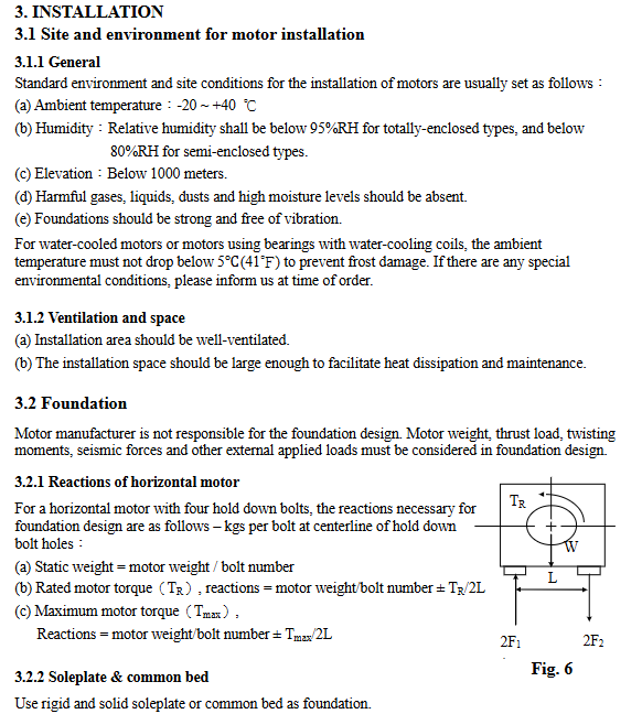
Basic requirements: A rigid base plate/common base should be used, and the foundation should bear the weight and thrust load of the motor, with a horizontal error of ≤ 0.04mm.
Transmission installation:
Couplings: Alignment error (rigid couplings ≤ 0.04mm/flexible couplings ≤ 0.05mm at speeds<2500rpm), end clearance ≤ 2.4mm.
Belt drive: Belt speed ≤ 35m/s, pulley diameter ratio (flat belt ≤ 5:1/V belt ≤ 8:1), pulley installed near the motor body.
Electrical wiring: compliant grounding, cable cross-section matching current, correct starting method and protector parameters, phase sequence verification to ensure correct direction of rotation.
(4) Run operation
Pre startup inspection:
Electrical: The wiring is correct, the insulation resistance meets the standard, and the protector is ready.
Mechanical: Bearing oil level (center of oil gauge), smooth rotation of oil ring, and no foreign object interference.
Auxiliary: The inlet water temperature of the water-cooled motor is 5-30 ℃, and the forced ventilation fan is started 15 minutes in advance.
Start limit: Up to 2 starts in cold state, only 1 start in hot state; Startup failure requires cooling for 30-60 minutes before attempting again. If the rotor does not rotate for 1-2 seconds, immediately stop the machine for troubleshooting.
Operation monitoring: As the load gradually increases, real-time monitoring of three-phase current (imbalance ≤± 5%), bearing temperature (≤ 95 ℃), and vibration (≤ 3.8mm/s) is carried out.
Maintenance and upkeep core
(1) Maintenance cycle and project
Key requirements for maintenance cycle core projects
Daily oil level check, oil ring rotation, leakage monitoring. The oil level is at the center of the oil gauge and there is no dripping or leakage
Every month, the bolts are tightened, the coupling is in good condition, and the filter is clean. All bolts are not loose, and the filter is not clogged
Quarterly insulation resistance testing and bearing grease replacement. If the insulation resistance is ≥ 5M Ω, grease should be added according to the bearing model (such as 6310, add 40g)
Every six months, the winding/exterior is cleaned and the oil is replaced. The winding is free of dust and oil stains, and the sliding bearings are replaced with rust proof turbine oil
Annual vibration testing, coupling re alignment vibration ≤ 3.8mm/s, alignment error ≤ 0.04mm
Open the cover for inspection every 2 years (without disassembling the rotor) to ensure that the coil does not change color and the bearings are not corroded
Disassemble and inspect the rotor bars and stator windings every 4 years for comprehensive testing
(2) Core component maintenance
Winding maintenance:
Cleaning: Compressed air (≤ 4kg/cm ²) or vacuum cleaning, wipe oil stains with safe solvents (chlorine containing solvents are prohibited).
Moisture proof: Use the space heater when idle to avoid coil condensation.
Testing: Measure with a 500VDC/1000VDC megohmmeter. If the resistance does not meet the standard, it needs to be dried.
Bearing maintenance:
Lubricating medium: default ExxonMobil Polyrex EM grease, mixing different types of grease is prohibited.
Lubricating specification: According to the bearing model (such as 6310, lubricate 40g every 2000 hours), lubricate during operation and then empty load for 10-30 minutes to remove the old grease.
Sliding bearings: Keep the oil level at the center of the oil gauge, change the oil every 6 months, and select the viscosity of the oil according to the number of poles (ISO VG32 for 2-pole).
Maintenance of transmission system:
Couplings: Regularly check the tightness of bolts, and realign if there is any abnormal vibration during operation.
Belt drive: Maintain uniform tension, with pulley diameter ≥ minimum recommended value (e.g. 45kW 4P motor V pulley ≥ 265mm).
Troubleshooting and Handling
Common causes and solutions for fault phenomena
Unable to start (no movement), power outage, broken wiring, missing fuses. Check power supply, repair wiring, install matching fuses
Start tripping/fuse melting winding short circuit, single-phase operation, overload detection winding insulation, troubleshooting wiring, reducing load
Overheating and overload during operation, ventilation blockage, excessive ambient temperature to reduce load, cleaning ventilation ducts, and improving environmental heat dissipation
Bearing high temperature/abnormal noise, insufficient lubrication, improper installation, bearing wear, replenishment of lubricating grease/oil change, re alignment, replacement of bearings
Excessive vibration, unbalanced rotor, insufficient foundation stiffness, eccentric rotor dynamic balance correction of coupling, reinforcement of foundation, adjustment of coupling
Recycling and Compliance
Material classification: Steel frame, copper winding, cast iron components are classified and recycled, and insulation materials are disposed of according to local regulations.
Hazardous waste: Lubricating oil is classified as hazardous waste and requires compliant recycling. Random discharge is prohibited.
Permanent magnet motor: Before recycling, it needs to be heated to 300 ℃ for demagnetization to avoid magnetic field interference with electronic devices.
- YOKOGAWA
- Reliance
- ADVANCED
- SEW
- ProSoft
- WATLOW
- Kongsberg
- FANUC
- VSD
- DCS
- PLC
- man-machine
- Covid-19
- Energy and Gender
- Energy Access
- Renewable Integration
- Energy Subsidies
- Energy and Water
- Net zero emission
- Energy Security
- Critical Minerals
- A-B
- petroleum
- Mine scale
- Sewage treatment
- cement
- architecture
- Industrial information
- New energy
- Automobile market
- electricity
- Construction site
- HIMA
- ABB
- Rockwell
- Schneider Modicon
- Siemens
- xYCOM
- Yaskawa
- Woodward
- BOSCH Rexroth
- MOOG
- General Electric
- American NI
- Rolls-Royce
- CTI
- Honeywell
- EMERSON
- MAN
- GE
- TRICONEX
- Control Wave
- ALSTOM
- AMAT
- STUDER
- KONGSBERG
- MOTOROLA
- DANAHER MOTION
- Bentley
- Galil
- EATON
- MOLEX
- Triconex
- DEIF
- B&W
- ZYGO
- Aerotech
- DANFOSS
- KOLLMORGEN
- Beijer
- Endress+Hauser
- schneider
- Foxboro
- KB
- REXROTH
- YAMAHA
- Johnson
- Westinghouse
- WAGO
- TOSHIBA
- TEKTRONIX
- BENDER
- BMCM
- SMC
- HITACHI
- HIRSCHMANN
- XP POWER
- Baldor
- Meggitt
- SHINKAWA
- Other Brands
- UniOP
- KUKA
- IBA
- Beckhoff
-
ADLINK PCI-8134 - 51-12403-0B20 PCB Board Motion Controller Card
-
ADLINK LPCI-3488A - PCI Card 51-12801-0A30 Low Profile IEEE-488 GPIB Card
-
ADLINK NUPRO-900A - industrial computer motherboard Single Board Computer
-
ADLINK cPCI-6840V - industrial control motherboard CompactPCI SBC
-
ADLINK M-342 - industrial motherboard ATX Mainboard
-
ADLINK NUPRO-935A/LV - industrial control motherboard
-
ADLINK cPCI-3538 - CompactPCI Async Serial Communications Module
-
ADLINK PCI-1610 - Card 4-Port RS-232 PCI Serial Communication Card
-
ADLINK HSL-DI32-DB-N - Distributed I/O Module 32-CH Digital Input
-
ADLINK CPCI-6860A - motherboard E7501 CompactPCI Single Board Computer
-
ADLINK PCI-8134A - 4-Axis Motion Control Card PCB Board
-
ADLINK EURESYS LINK - grabbers Video Capture Card Frame Grabber
-
ADLINK NuPRO-965DV - motherboard Industrial Control Board
-
Thermo Fisher Scientific 80100-60500 - 80000-61010R 80000-21000R 80000-60457 Spectrum System Controller ADLINK Components
-
ADLINK PCI-7296 - IO card High Density 96-CH Opto-Isolated DIO Card
-
ADLINK MXC-6322D - Matrix Industrial Computer Fanless Embedded PC
-
ADLINK DIN-825-GP4 - connector board Terminal Block Interface
-
ADLINK AMP-208C - Motion Control Card DSP-based 8-axis
-
ADLINK PCIe-GIE72 - 51-18531-0A10 2-CH GigE Vision Frame Grabber PoE+ Card
-
ADLINK PXIS-3320 - PXI/PXIe Chassis 15-slot 6U PXI/CompactPCI SEM-I-1518=9N41
-
ADLINK MI-965 - Industrial CPU Motherboard
-
ADLINK M-302 - Industrial control motherboard
-
ADLINK PCI-6308V - 51-12202-0A50 Isolated Analog Output Card PCB-I-E-1813=ZA03
-
ADLINK NUPRO-935A - Industrial Mother Board CPU Board
-
ADLINK PCI-7434 - PLOTECH Digital Output Card PCB-I-E-1182=6EX2
-
ADLINK PCI-7432 - 64 Channel Isolated Digital I/O PCI CARD
-
ADLINK NUPRO-935A/DV - 51-41802-0A10 motherboard Industrial Control Board
-
ADLINK PCIe-GIE72 - 51-18531-0A10 2-CH GigE Vision Frame Grabber PoE+ Card
-
ADLINK HSL-DI16DO16-M-NN - HSL-DI16DO16-M-NN(G)-0280 Discrete I/O Module Distributed I/O
-
ADLINK cPCI-6760D / cPCI-6840V - cPCI Single Board Computer Industrial Motherboard
-
ADLINK NuPRO-A301 - Motherboard IPC Motherboard
-
ADLINK NuPRO-935A/LV - motherboard Industrial Control Board
-
ADLINK NUPRO-E320LV - motherboard Industrial Control Board
-
ADLINK NuPRO-E42 - Industrial Control Board Motherboard
-
ADLINK M-342 - ATX Motherboard Industrial PC Mainboard
-
ADLINK CPCI-6860 / 6860A - Industrial Control Motherboard CompactPCI SBC
-
ADLINK AmITX-SL-G-Q170/GEHC(EA)-021E - 51-7A104-0A20 Industrial Motherboard w/ DDR4
-
ADLINK NUPRO-852 / NUPRO-852LV - industrial control motherboard
-
ADLINK DAQ-2006-004 - Multi-Function DAQ Cards Data Acquisition
-
ADLINK PCIe-RTV24 - Frame Grabbers Video Capture Cards PCI-e x1 4-CH 120fps
-
ADLINK PCI-8134 - 51-12403-0B20 4-Axis Motion Controller Card
-
ADLINK PCI-8132 - 2-Axis Motion Controller Card
-
ADLINK cBP-6402 - Backplane Passive Backplane
-
ADLINK cPCI-6760D - cPCI Single Board Computer Industrial Control Motherboard
-
ADLINK DIN-825-4PO(G)-0030 - Terminal Board Motion Control Breakout Board
-
ADLINK M-322 - Industrial Motherboard
-
ADLINK ABX-1301 - 51-63808-0A20 Industrial Motherboard
-
ADLINK PCI-7433 - 64-CH Isolated Digital Input Card
-
ADLINK AMP-208C - Motion Control card
-
ADLINK DIN-50S-01 - TECHNOLOGY TERMINAL BLOCK INTERFACE MODULES W/ DIN RAIL
-
ADLINK PCI-8134 - 51-12403-0B20 4-Axis Motion Controller Card
-
ADLINK MXE-201/MSSD64G - Technology Automation Computer Fanless Embedded System
-
ADLINK USB-3488A (G) - USB to GPIB CARD Controller Interface
-
ADLINK cPCI-3720L2 - SBC Single Board Computer PCB AMAT 0190-14599
-
ADLINK PCI-7251 - Relay Output Board Expansion Module
-
ADLINK PCI-8124-C - PCB Board 4-CH Encoder Trigger Card
-
ADLINK HD636 - Industrial Computer Board PCB-I-E-2200=9L32-2 Main Board
-
ADLINK USB-3488A - THERMOTRON INDUSTRIES IEEE 488 CPU INTERFACE WITH USB/GPIB
-
ADLINK MI-965 - motherboard Industrial CPU Board
-
ADLINK LPCIe-7250 - Technology Digital IO card Low Profile PCIe Relay Output
-
ADLINK NuPro-720/SCOPUS - Technology With 256MB Industrial MotherBoard
-
ADLINK NuPR0-840 - industrial control motherboard
-
ADLINK M-342 - Motherboard ATX PC Mainboard
-
ADLINK MI-965 - motherboard Industrial CPU Board
-
ADLINK CPCI-6530V/4402E/M4G - AMAT CPCI-6503VED/4402E/M4-0/SD64G-2550 Universal SBC
-
ADLINK IMB-M43-IRV - Industrial Motherboard ATX PC Board
-
ADLINK 52983 / 58183 - Chroma PXI I/O Input/Output Card + Carrier Adapter
-
ADLINK PXI-3920 - PXI 3U cPCI Industrial Controller w/ RAM SSD Embedded CPU
-
ADLINK NuPRO-842LV/P - motherboard Industrial Control PC Board
-
ADLINK PCI-7442 - 64-Channel Datalogging Acquisition Switch Card
-
ADLINK PCIe-RTV24 - Cadre Agrippeurs Vidéo de Capture Cartes Pci-E x1 4-CH
-
ADLINK ACL-7122A - TECHNOLOGY 51-11004-1A1 CIRCUIT BOARD 96-CH DIO Card
-
ADLINK PCIe-RTV24 - 51-18016-0A20 Image Acquisition Video Capture Card
-
ADLINK AMP-204C - DSP-Based 4-Axis Advanced Pulse-Train Motion Controller
-
ADLINK 52981 / 58183 - Chroma PXI Digital I/O DIO Input/Output Card + Carrier Adapter
-
ADLINK PCI-8102 - motion control card 2-Axis
-
ADLINK NuPRO-E320LV - industrial computer motherboard
-
ADLINK PCI-RTV24 - card Analog Video Capture Frame Grabber
-
ADLINK M-302 - Motherboard P/N: 08GSAQ96501102
-
ADLINK NEON-1020 - Smart camera Industrial Machine Vision
-
ADLINK AMP- 208C - card DSP-based 8-axis Motion Controller
-
ADLINK PCI-9114DG - Multi-Function Daq Card Data Acquisition
-
ADLINK MXC-6322D/BE_FanG) - Matrix PM2-MXC Fanless Embedded Computer
-
ADLINK DIN-825-4P0 - Terminal Board Motion Control Breakout Board
-
ADLINK HPCI-8S4 REV.B2 - Industrial Control Base Plate Passive Backplane
-
ADLINK HSL-DI32-DB-N - Distributed I/O Module 32-CH Digital Input
-
ADLINK NuPRO-935A/DV - industrial control motherboard
-
ADLINK PCI-7442 - Switch card 64-CH Datalogging Acquisition Card
-
ADLINK NuPRO-E42 - motherboard 51-41808-0A30 Industrial Motherboard
-
ADLINK CPCI-3610D/N45/M1G(G)-10B0 - CompactPCI Intel Atom Single Board Computer CPU Board
-
ADLINK LPCI-7250 - GP Output Isolated Digital Input Card PCB 51-12803-0A10
-
ADLINK PCI-7250 - 51-12007-0A40 PCI7250 8-CH Relay Output & 8-CH Isolated DI Card
-
ADLINK STC-1005 - 10.4inch touch panel PC E3845 CPU
-
ADLINK PCI-FIW64 - image card FireWire Frame Grabber
-
ADLINK NuPRO-935A/LV - industrial computer motherboard
-
ADLINK PCI-8164 00B0 - Centralized Motion Controller 4-axis PCB-I-E-1179=6EX2
-
ADLINK ACLD-9137F REV A1 - 51-14006-101 Screw Termination Board
-
ADLINK PCI-7248 - 51-12006-0A40 Control Card Digital I/O
-
ADLINK HPCI-8S4 - Technology Backplane PCB GaSonics 3500 Asher Passive Backplane
-
ADLINK NuPRO-E320LV - Cpu Board 51-41804-0A20 Industrial Motherboard
-
ADLINK HPX-13S4 - device baseboard Passive Backplane
-
ADLINK M-322 - industrial motherboard
-
ADLINK NuPRO-865 REV :3.0 - industrial motherboard
-
ADLINK DIN-68S-01 - Terminal Block Interface Module Cable Connection
-
ADLINK ETX-IM266-C100Z - motherboard ETX CPU Module
-
ADLINK NuPRO-E320LV - motherboard Industrial Control Board
-
ADLINK NuPRO-841 REV:2.0 - motherboard Industrial PC Board
-
ADLINK ETX-AT-N270-18 - N270 Board ASH-EAT-18/S512 ET Mainboard
-
ADLINK PCI-RTV24 - Image capture card Analog Frame Grabber
-
ADLINK PCI-8102 - card 2-Axis Motion Controller
-
ADLINK M-322 - industrial motherboard
-
ADLINK PCI-9114 REV.C2 - acquisition card Multi-Function DAQ
-
ADLINK NuPRO-865 REV :3.0 - industrial motherboard
-
ADLINK DIN-68S-01 - Terminal Block Interface Module Cable Connection
-
ADLINK M-322 - Industrial Motherboard Mainboard
-
ADLINK CPCI-6860A - E7501 dual Xeon CPCI Single Board Computer
-
ADLINK MXC-6301D(G) - Technology Expandable Fanless Embedded Computer i7-3610E
-
ADLINK NuPRO-842LV - 51-41360-0B1 Industrial Motherboard
-
ADLINK PBP-08A7 R1MO - PCB Industrial Computer Backplane Passive Backplane
-
ADLINK PCI-3488 - PCI BOARD IEEE-488 GPIB Controller Card
-
ADLINK NuPRO-935A/LV - Industrial Control Motherboard
-
ADLINK PCI-8134 - TECH 4-AXIS MOTION CONTROLLER 4209NB2039 AT23A
-
ADLINK Karbon 700-X2 - Expanded High-Performance Rugged Edge Computer Windows 10
-
ADLINK PCIe-9852 - ADcard 2-CH 8-Bit 200MS/s Digitizer Card
-
ADLINK ETX-BT-E3815 - Industrial Control Module NO AUDIO 91-71116-E020 CT66
-
ADLINK cPCI-8168-006 - cPCI NulPC Motion Control Board
-
ADLINK NuPRO-E43 - 51-41809-0A30 industrial motherboard
-
ADLINK PCI-8134A - PCB Board Motion Controller Card

K-JIANG

Add: Jimei North Road, Jimei District, Xiamen, Fujian, China
Tell:+86-15305925923