
K-WANG


GE VMIPCI-5565 Ultrahigh Speed Fiber-Optic Reflective Memory with Interrupts
GE VMIPCI-5565 Ultrahigh Speed Fiber-Optic Reflective Memory with Interrupts
Product Overview
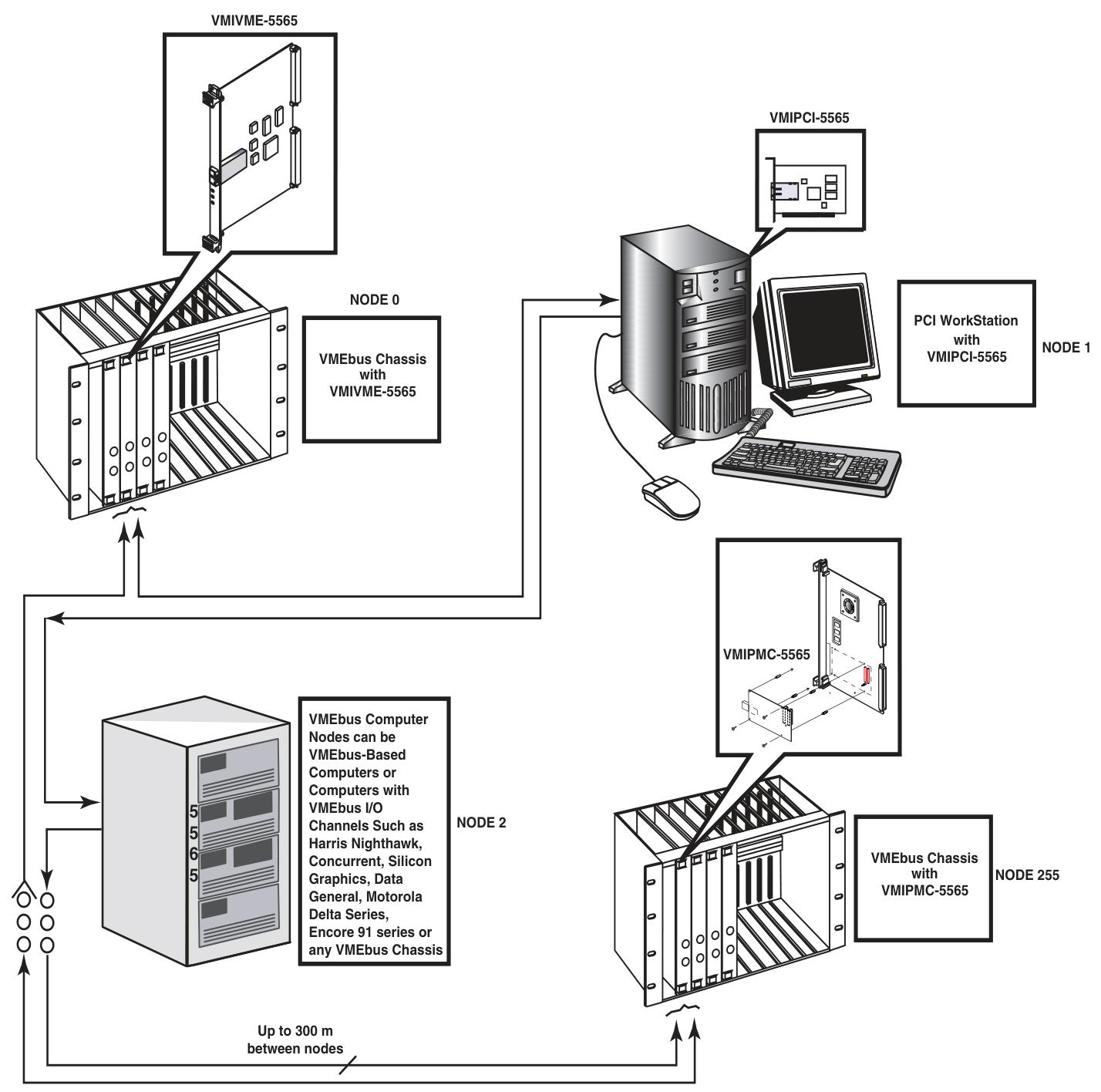
Basic information: VMIPCI-5565 is a PCI based reflective memory real-time fiber optic network product for GE Fanuc embedded systems, belonging to the VMIxxx-5565 series. It can be integrated into the network with other members of the series through standard fiber optic cables, and each board is called a node, allowing computers and other devices with different architectures and operating systems to share data in real time.
Key Features
A high-speed and easy-to-use fiber optic network with a serial rate of 2.12 Gbaud.
Supports PCI 64 bit 66MHz transmission, network operation does not require the involvement of a host processor.
Equipped with redundant operation mode, supporting up to 256 nodes.
The multi-mode fiber optic connection distance can reach up to 300 meters, and the packet size is dynamically variable (4-64 bytes).
The transmission rate varies depending on the packet size, with 47.1MB/s for 4-byte packets and 174MB/s for 64 byte packets.
Equipped with 64MB or 128MB SDRAM reflective memory with parity check, as well as two independent direct memory (DMA) channels, configurable byte order conversion to accommodate multiple CPU architectures on the same network.
Operating principle
Basic operation: Each node in the network is interconnected in a daisy chain loop through fiber optic cables, and each node needs to have a unique node ID (set through 8 onboard jumpers). The data transmission is initiated by the PCI host system writing data to the onboard SDRAM. During the writing process, the onboard circuit automatically writes the data and related information into the transmit FIFO, forming variable length data packets that are transmitted through the fiber optic interface. The receiver opens the data packet and stores it in the receive FIFO, then writes it into the local SDRAM and routes it to its own transmit FIFO until the data returns to the source node and is removed.
Register group: including PCI configuration registers, local configuration registers, runtime registers, DMA control registers, reflective memory (RFM) control and status registers. The functions and purposes of each register group are different, and some registers have different initialization methods and modification frequencies.
Reflective memory RAM: There are two specifications, 64MB or 128MB, with parity check. The starting position is specified by the base address register 3. The parity check function needs to be enabled by setting a specific register, and write operations need to be performed at the 32-bit or 64 bit boundary.
Interrupt circuit: There is a single PCI interrupt output (INTA #), and the interrupt source can be enabled and monitored separately through multiple registers. The interrupt circuit is divided into two layers, and the second layer interrupt is transmitted to the first layer through the LINTi # signal.
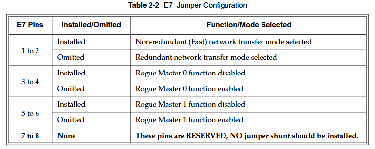
Redundant transmission mode: Removing the jumper blades between pins 1-2 of jumper E7 can configure it as redundant mode. At this time, each data packet is transmitted twice, and the receiving circuit evaluates the transmission situation. Although this mode reduces the probability of data loss, it will also lower the effective network transmission rate.
**Rogue packet removal operation * *: Rogue packets are packets that do not belong to any node in the network. VMIPCI-5565 can run as one of the two Rogue hosts to detect and remove rogue packets. After detection, relevant flags will be set and PCI interrupts can be triggered.
Configuration and Installation
Unpacking procedure: Components are sensitive to static electricity and should be handled on conductive materials. When not in use, they should be stored in their original packaging. Upon receipt, they should be inspected for any transportation damage and claims should be promptly processed.
Jumper configuration and position
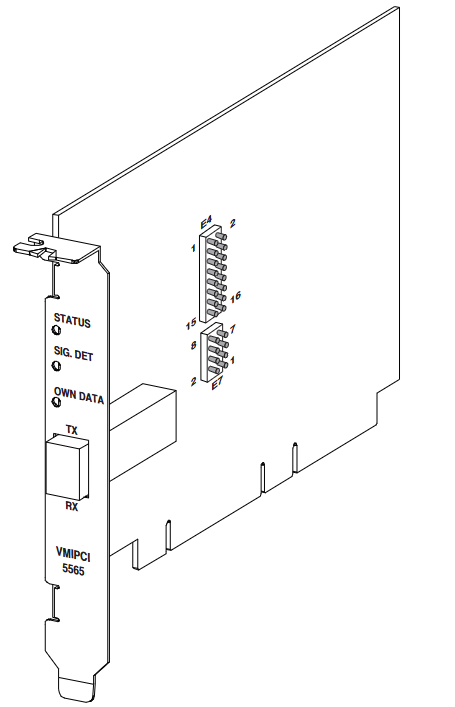
The node ID is set by the 8 jumper blades of jumper block E4, and each node ID needs to be unique. Install the jumper blade so that the corresponding bit is low (0), and remove it so that it is high (1).
Jumper E7 controls three functions: 1-2 pins select non redundant or redundant network transmission mode, 3-4 pins enable or disable rogue host 0 function, 5-6 pins enable or disable rogue host 1 function, 7-8 pins are reserved pins and should not be installed with jumper blades. The default configuration is to install jumper blades on all pins except 7-8.
Physical installation: Before installation, it is necessary to ensure that the node ID and operation mode have been set. Power off the installation, firmly insert the board into the PCI connector and fix the screws, then reinstall the chassis cover and turn on the power. The board design complies with the PCI 2.2 specification.
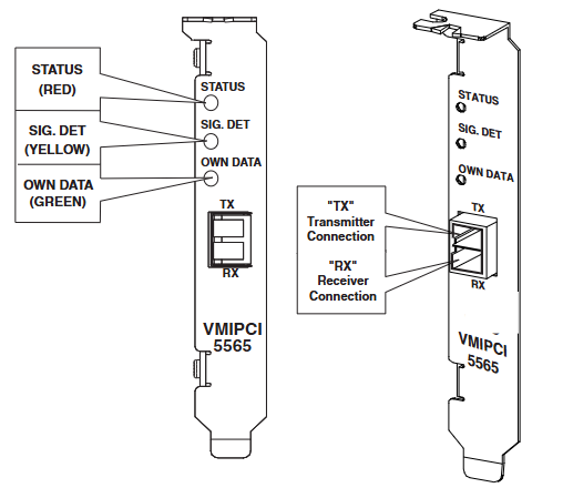
Front panel description: There are three LED indicator lights, the red status LED is user-defined, and it is on by default when turned on. The status can be switched by writing to bit 31 of the control and status registers; The yellow signal detection LED lights up when the receiver detects light; The green self data LED lights up when it detects the return of its own data. There are also "RX" receiver ports and "TX" transmitter ports, which use "LC" type fiber optic cables. Dust caps should be installed when not connected to the cables, and eye injuries should be avoided when not powered.
Cable configuration: Provides cable specifications and connector specifications for multimode or single-mode fiber optic interfaces, including core diameter, cladding diameter, sheath outer diameter, attenuation, bandwidth, and other parameters, as well as connector compatibility, insertion loss, and other information.
Connectivity: Nodes are connected in a circular manner, as in the example of a circular connection of six nodes.
Programming
PCI configuration register: located in the 256 bytes of the PCI configuration space, the first 64 bytes are predefined headers that contain information such as vendor ID and device ID. Some registers can be modified by the user, while others are read-only or initialized by the system BIOS.
Local configuration registers: can be accessed through base address register offset 0 or 1, initialized to normal working configuration by serial EEPROM, and some registers can be modified by users to match the host system.
Runtime register: It is also accessed through the base address register offset 0 or 1, and will not be initialized by the serial EEPROM, maintaining the default state when the PCI bus is reset. Users need to modify some bits to activate the desired operating mode.
DMA control register: accessed through offset 0 or 1 of the base address register, it defaults to the PCI reset state and needs to be modified by the user to activate the operating mode, including DMA channel mode register, address register, etc., used to operate two DMA engines.
RFM control and status register: located in PLX local address space 0, the base address is specified by "PCI base address 2" in the PCI configuration register, including board revision register, node ID register, etc., to achieve the unique function of reflecting the memory board.
DMA operation example: It is necessary to find the value of the base address register 0, set five DMA registers, and then start the transfer and monitor the completion status by writing to the command/status register.
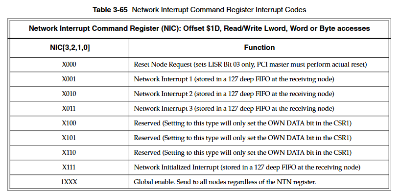
Example of network interrupt handling: including setting steps (clearing previous interrupts in FIFO, setting relevant registers to enable interrupts, etc.) and steps for serving network interrupts (reading registers to determine interrupt source, processing data and sender ID, etc.).
Maintain and comply with information
Maintenance: When the product malfunctions, it is necessary to first check the software, system configuration, electrical connections, etc. If a return is required, please contact GE Fanuc Embedded Systems to obtain a Return Merchandise Authorization (RMA) number. User level repairs are not recommended, and the drawings and charts in the manual are for reference only.
Compliance information: Complies with multiple international standards and regulations, such as the EU's EN series standards, the US FCC Part 15, and Australia/New Zealand's AS/NZS CISPR 22. Compliance requirements and restrictions vary in different regions.
- YOKOGAWA
- Reliance
- ADVANCED
- SEW
- ProSoft
- WATLOW
- Kongsberg
- FANUC
- VSD
- DCS
- PLC
- man-machine
- Covid-19
- Energy and Gender
- Energy Access
- Renewable Integration
- Energy Subsidies
- Energy and Water
- Net zero emission
- Energy Security
- Critical Minerals
- A-B
- petroleum
- Mine scale
- Sewage treatment
- cement
- architecture
- Industrial information
- New energy
- Automobile market
- electricity
- Construction site
- HIMA
- ABB
- Rockwell
- Schneider Modicon
- Siemens
- xYCOM
- Yaskawa
- Woodward
- BOSCH Rexroth
- MOOG
- General Electric
- American NI
- Rolls-Royce
- CTI
- Honeywell
- EMERSON
- MAN
- GE
- TRICONEX
- Control Wave
- ALSTOM
- AMAT
- STUDER
- KONGSBERG
- MOTOROLA
- DANAHER MOTION
- Bentley
- Galil
- EATON
- MOLEX
- Triconex
- DEIF
- B&W
- ZYGO
- Aerotech
- DANFOSS
- KOLLMORGEN
- Beijer
- Endress+Hauser
- schneider
- Foxboro
- KB
- REXROTH
- YAMAHA
- Johnson
- Westinghouse
- WAGO
- TOSHIBA
- TEKTRONIX
- BENDER
- BMCM
- SMC
- HITACHI
- HIRSCHMANN
- XP POWER
- Baldor
- Meggitt
- SHINKAWA
- Other Brands
- UniOP
- KUKA
- IBA
- Beckhoff
- ADLINK
-
Beckhoff AX5118-0000 - Servo Drive Module
-
Beckhoff CP2921-2000-0000 - Multi-Touch Control Panel
-
Beckhoff CX1020-0000 - CX1020-N000 CX1100-0001 Controller Set
-
Beckhoff CX8110 - 000007735 Embedded PC
-
Beckhoff CP7031-0002-0000 - CP-Link Interface Control 12.1" Panel
-
Beckhoff AX8118-0200-0000 - Single-Axis Module Motion Drive
-
Beckhoff CX2030-1020 - Basic CPU Module
-
Beckhoff CX5120-0125 - Embedded PC
-
Beckhoff CP2913-0000 - Multi-Touch Display 12.1" 1280 x 800 DVI USB 24VDC
-
Beckhoff CP6902-0001-0000 - Operator Interface 15" CP690200010000
-
Beckhoff ELM3502-0000 - EtherCAT Measurement Terminal 2-channel analog input
-
Beckhoff CX1030-0012 - CPU Module with CX1100-0014 CX1030-N041 CX1030-N030 N000
-
Beckhoff CP3915-0000 - 15" HMI Multi-Touch Panel
-
Beckhoff CU8803-0001 - CU8803-0000 Rev 2.2 Transmitter Box CP-Link 4
-
Beckhoff CX2030-0125 - CPU Module Embedded PC Windows PLC Controller
-
Beckhoff CX1020-0122-1001 - Multivac 105808023 CPU Module
-
Beckhoff CX2020-0121 - Embedded PC Module
-
Beckhoff KL3162 - PLC Module 2-channel analog input terminal
-
Beckhoff CP6607-0001-0020 - Built-in Panel PC Touchscreen 5.7" Arm Cortex-A8 1 GHz
-
Beckhoff EL3751 - EtherCAT Terminal 1 Channel Analog Input Multifunction 24 Bit
-
Beckhoff CX1010-0012 - CPU Module CX1010-0012
-
Beckhoff EL6631 - EtherCAT 2-Port Communication Interface Profinet RT Controller
-
Beckhoff C1510.1 - Interface Card
-
Beckhoff CX8080 - Embedded PC PLC Module
-
Beckhoff EL3218 - EtherCAT Terminal 8-Channel Analog Input
-
Beckhoff CP6700-0500 - Panel Control Flash PC Touch Screen 10.1" HMI
-
Beckhoff CP7011-1002-0010 - Polaris Operator HMI Display 30.5 cm
-
B&R 5AP920.1505-01 - TFT Display With Touch Screen
-
Beckhoff EL3351 - PLC Module Thermocouple Input Terminal
-
Beckhoff AM8052-0JH1-0000 - Servo Motor
-
Beckhoff CX5140-0135 - 4GB High-Performance Embedded Industrial PC
-
Beckhoff EP7211-0034 - EtherCAT Box 1 Channel Motion Interface
-
Beckhoff CX1020-0121 - CPU Module with CX1100-0002 CX1020-N010 N000
-
Beckhoff CX5140-0100 - 4GB Embedded PC
-
Beckhoff CP7711-0001-0030 - Industrial Computer Detection Panel
-
Beckhoff CX1020-0122 - CX1020-N030 CX1020-N010 CX1020-N000 CPU Module
-
Beckhoff CP6907-1000-0000 - Control Panel HMI
-
Beckhoff CX1020-0122 - CX1020-N030 CX1020-N000 CPU Module
-
Beckhoff CX2020-0123 - Embedded PC with CX2100 Power Supply
-
Beckhoff BX5100-0000 - Bus Terminal Controller Bus Coupler
-
Beckhoff C6930-0050 - Industrial Computer
-
Beckhoff CP6606-0001-0020 - Industrial Panel PC
-
Beckhoff CX9020-0115 - PLC Module CX90200115
-
B&R X20-SL-8000 - Ethernet Powerlink X20 Safety Controller Module Rev H0
-
Beckhoff CX2020-0155 - CPU Basic Module + Power Supply Module CX2100-0004
-
Beckhoff EJ7211-0010 - EtherCAT Plug-in Module Servomotor Motion Interface
-
Beckhoff C6920-0010 - Industrial PC Computer
-
Beckhoff CX1020-0112 - CPU Module with CX1020-N010 CX1020-N000 CX1100-0004
-
Beckhoff AX5203-0000 - Servo Driver Module
-
Beckhoff C6640-0050 - Industrial PC Intel Core i7-6700 3.4GHz CB1064-0002 Board
-
Beckhoff CX1020-0112 - CPU Module with CX1020-N000 CX1020-N010 CX1020-N030
-
Beckhoff CP6201-0001-0020 - Panel PC 24VDC
-
Beckhoff CX2020-0122 - Embedded PC Controller
-
B&R 5PC810.SX02-00 - Controller PC
-
B&R 4PP220.1043-K08 - REV G HMI Touch Panel 10.5in
-
B&R X20CP1586 - CPU Module
-
Beckhoff CX2040-0155 - Basic CPU Module Along with 40GB Card V 964
-
Beckhoff EL6652 - EtherCAT Terminal EtherNet/IP Master Scanner Rev 0018
-
Beckhoff C6650-0060 - Industrial PC
-
Beckhoff EP2328-0002 - EtherCAT Box 4-channel digital input 4-channel digital output
-
Beckhoff CX5120-0135 - Embedded PC CPU Module Intel Atom Processor 2GB RAM
-
Beckhoff CP7037-1037-0010 - Operator Interface Touchscreen
-
Beckhoff CX5140-0100 - 4GB Embedded PC
-
Beckhoff C5240-0020 - 000224115 Plc Module
-
Beckhoff CX5140-0100 - 4GB Embedded PC
-
Beckhoff EL2911 - 4 Channel Digital Input + 1 Channel Digital Output Module
-
Beckhoff CX1020-0000 - CX1020-N000 Automation Controller
-
Beckhoff CP2918-0000 - Control Panel HMI
-
Beckhoff CX2020-0122 - Embedded PC Controller
-
Beckhoff C6640-0040 - Control Cabinet Industrial PC 7-Slot
-
Beckhoff CP6201-0001-0020 - Touch Display Panel with Accessories
-
Beckhoff CP6207-0001-0020 - Panel PC 24VDC
-
Beckhoff C6930-1062-0050 - Control Cabinet Industrial PC
-
Beckhoff CP2712-1002-0000 - Baumann Automation Touch Control Panel
-
Beckhoff EL6631-0010 - EL66310010 Module PLC PROFINET RT Device
-
Beckhoff BK9000 - Ethernet TCP/IP Bus Coupler
-
Beckhoff CX5140-0175 - Embedded PC
-
Beckhoff CP2912-0000 - 12.1" Touch Screen Display CP29120000 24VDC
-
Beckhoff CP2712-1002-0000 - Baumann Automation Touch Control Panel
-
Beckhoff EK1100 - EtherCAT Coupler Reseller Lot of 38 with EK1122
-
Beckhoff KL1414 - 4-Channel Digital Input 24V DC 0.2ms 10 Piece Box
-
Beckhoff CP6533-0001-0060 - Control Cabinet PC Panel
-
Beckhoff EK9500 - EtherNet/IP Bus Coupler
-
Beckhoff CP6202-1047-0050 - Built-in Panel PC
-
Beckhoff C6017-0010 - Ultra-Compact Industrial PC Serial 000sndlk
-
Beckhoff C6650-0040 - Industrial PC
-
Beckhoff CX5230-0185 - 000119805 PLC Module 3D-71
-
Beckhoff EL3773 - Power Monitoring EtherCAT Terminal PLC Module
-
Beckhoff EL4732 - EtherCAT Terminal 2-channel analog output Pack of 10
-
Beckhoff CX1001-0120 - CPU Module cx10010120 cx1000-n001 cx1000-n000
-
Beckhoff CP6202-0001-0020 - Industrial Panel PC Atom Z530 32GB SSD 1GB RAM
-
Beckhoff CX5140-0175 - Embedded PC Intel Atom E3845 4GB RAM + 40GB CFast Card
-
Beckhoff EL3751 - EtherCAT Terminal 1 Channel Analog Input Multifunction 24 Bit
-
Beckhoff CP6202-0001-0010 - Economy Built-In Panel PC with HDD
-
Beckhoff C6320-M554 - Industrial PC
-
B&R 2AT300.6 - Analog Input Module 8x PT100
-
Beckhoff AX5206-0000-0202 - Digital Compact Servo Drive 2-axis
-
Beckhoff CX1020-0111 - CX1020-N000 CX1020-N010 CX1020-N030 CPU Module Bundle
-
Beckhoff CP6606-0001-0020 - Panel PC HMI
-
Beckhoff CX2020-0155 - CPU Basic Module + Power Supply Module CX2100-0004
-
Beckhoff CP2712-0000 - Panel 12.1" 24VDC CP27120000
-
Beckhoff C6150 - Control Cabinet PC
-
Beckhoff CP7711-0001-0030 - Industrial Computer Detection Panel
-
Beckhoff CP2913-0000 - Multi-Touch Display 12.1" 1280 x 800 DVI USB 24VDC
-
Beckhoff EK1322 - EtherCAT P Junction Module
-
Beckhoff CP6500-1012-0060 - 14250369 Control Cabinet PC
-
Beckhoff CP7902-0001-0000 - Control Panel HMI
-
Beckhoff EL6631-0010 - EL66310010 Module PLC PROFINET RT Device
-
Beckhoff CP2712-1002-0000 - Baumann Automation Touch Control Panel
-
Beckhoff C6920-0010 - Industrial PC Core Duo 2.00 GHz
-
Beckhoff C3640-0050 - Industrial PC
-
Beckhoff CX5140-0100 - 4GB Embedded PC
-
Beckhoff C6015-0010 - Ultra-Compact Industrial PC
-
Beckhoff KL3001 - PLC Module Analog Input Bus Terminal
-
Beckhoff CP7711-0001-0030 - Industrial Computer Detection Panel
-
Beckhoff AX5106-0000-0200 - Digital Compact Servo Drive 1-axis
-
Beckhoff CP2712-0000 - 12.1" 24VDC Touch Screen CP27120000
-
Beckhoff CP7037-1037-0010 - Operator Interface Touchscreen
-
Beckhoff CP7711-0001-0030 - Industrial Computer Detection Panel
-
Beckhoff C6220 - Industrial PC with Beckhoff FC3101 240 Volt
-
Beckhoff EL3164 - 4X Analog Input EtherCAT Terminal
-
Beckhoff C6140 - Husky PC 11 Industrial PC 160GB HDD Intel P3 850MHz w SERCOS 24V
-
Beckhoff KL6023-0000 - KL6023 EnOcean Wireless-Adapter
-
Beckhoff C3620-0000 - Industrial PC Motor Shelves
-
Beckhoff CX2020-0120 - PLC Module & CX2100-0004 PLC
-
Beckhoff Monitor - Industrial Display Screen
-
Beckhoff CP6020-0000-0000 - Touch Panel Screen
-
Beckhoff EK1960-0000 - TwinSAFE Compact Controller

K-JIANG

Add: Jimei North Road, Jimei District, Xiamen, Fujian, China
Tell:+86-15305925923