
K-WANG


GE VMIVME-111 64 bit High Voltage Digital Input Board
GE VMIVME-111 64 bit High Voltage Digital Input Board
Product Overview
VMIVME-111 is a 64 bit high-voltage digital input board with built-in testing capabilities, compliant with the VMEbus specification, and featuring a dual height European card design. It is suitable for scenarios that require monitoring multiple digital input signals and is compatible with the intelligent I/O controller series of GE Fanuc embedded systems. It supports hot swappable replacement and is software compatible with VMIVME-1110.
Core Features
Equipped with 64 bit differential or high-voltage digital input.
Each group of 32 inputs can be monitored through jumper selection: contact closure, voltage source, current absorption, or differential signal.
An open circuit can provide logic 0 or (jumper optional) logic 1.
Equipped with input filter options.
The onboard built-in testing logic is used for fault detection and isolation.
The front panel is equipped with a fault LED indicator light.
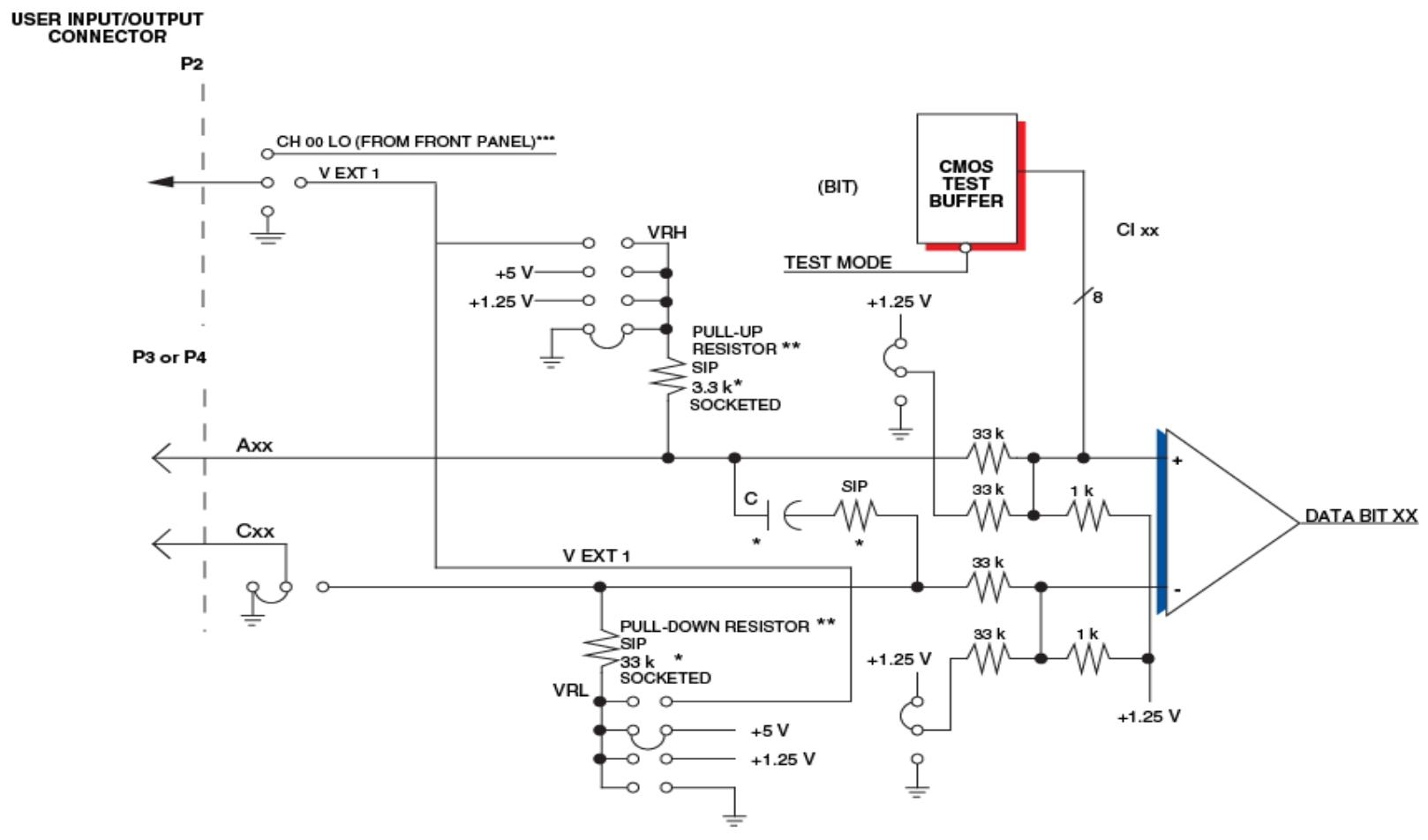
Users can choose to input a voltage threshold (1.25 to 66V).
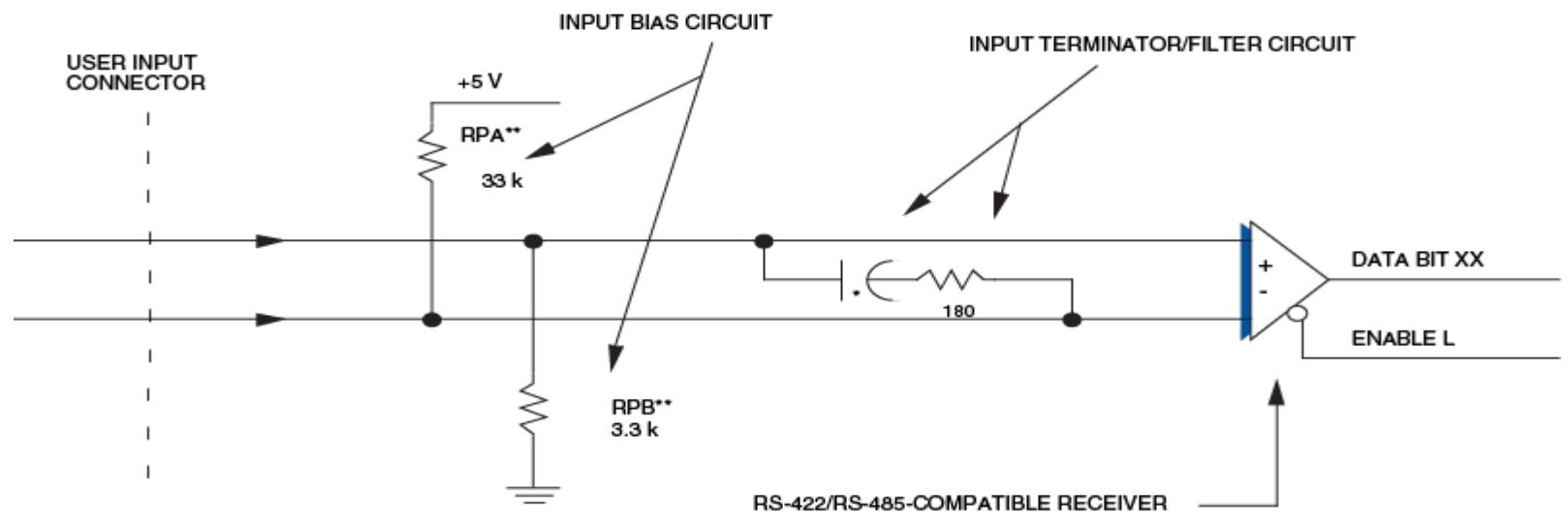
Compatible with RS422/RS485 differential line receiver, providing ± 7V noise immunity.
Supports 8-bit, 16 bit, or 32-bit data transmission.
Adopting high reliability DIN type I/O connectors.
By using the corresponding suppression panel (such as VMIVME-3451), optical isolation can be achieved, which meets the surge protection requirements of ANSI/IEEE STD C37.90.1-1982.
Ordering Options
A=0 (option reserved for future use).
B is the input filter/terminator option: 0 is with input filter/terminator (the input filter/terminator circuit can provide a series RC terminator or input filter through jumper selection, with a time constant of 0.14ms, used for receivers compatible with RS422/RS485); 1 is without input filter/terminator; 2 is a 2 μ s filter; 3 is a 10 μ s filter; 4 is a 5ms filter; 5 is a 1ms filter.
C=0 (option reserved for future use).
Connector data
Compatible cable connector: Panduit No.120-964-435.
Strain relief: Panduit No.100-000-072.
Printed circuit board plug connector: Panduit No. 120-964-033A (also known as ITW/Pancon).
Functional characteristics
Compatibility: Compatible with VMEbus specifications, dual height appearance.
Input connector type: Dual 64 pin connector - DIN 41612.
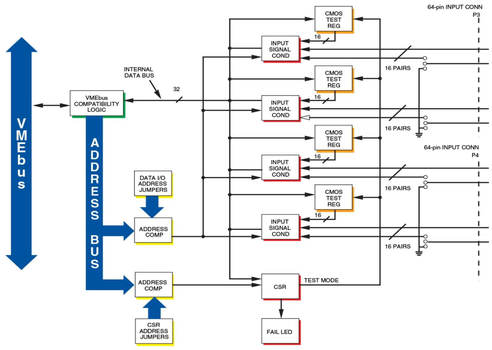
I/O organization: 8 input ports, each 8 bits wide, addressable to any address within the short monitoring and/or short non privileged I/O mapping, control and status register (CSR) addresses can be independently selected.
Addressing scheme: 8 ports can be individually addressed on 8-bit, 16 bit, or 32-bit boundaries, 1 CSR can be addressed on 8-bit boundaries, and 13 jumpers provide unlimited short data I/O address mapping options.
Differential signal input characteristics: The common mode input voltage range is -30 to+66V, and the input sensitivity is ± 100mV within the common mode range of -7 to+12V. The input impedance is high (33k Ω).
Single ended signal input characteristics: high input impedance (33k Ω), threshold accuracy of 1% (typical value) across the entire 66V range.
Signal conditioning input filter terminator option: A board with input signal filtering circuit can be ordered. For differential input, the circuit consists of a series resistor and a capacitor, which are connected across the signal input terminals; For single ended inputs, this circuit provides users with the option to select an input debounce filter with a time constant.
Built in testing: Designed with internal self-test logic to test all active components, providing special output registers to generate 16 bit data words for health testing during real-time or offline operations. CSR provides special test mode bits to enable the output test registers to drive differential receivers. The front panel fault LED lights up when powered on and can be turned off under program control after successfully completing user-defined diagnostics.
Physical/Environmental Specifications
Power requirements:+5V, typical value 1.4A, maximum value 2.0A.
Cooling: forced air convection.
Temperature: Operating temperature from 0 to 55 ° C, storage temperature from -20 to 85 ° C.
Humidity: 20 to 80%, no condensation.
Mean Time Between Failures (MTBF): Please contact the factory.
Related products and applications
For inter channel optical isolation and surge suppression that comply with ANSI/IEEE STD C37.90.1-1982 (IEEE-472), please refer to VMIVME-3451 specification.
Threshold voltage
When R=3.3k Ω, the threshold voltage formula is
Vt=[(V−1.25)(.91)]+1.25
The Vt values corresponding to different voltages are as follows: 1.25V corresponds to 1.25V, 5V corresponds to 4.7V, 12V corresponds to 11V, 24V corresponds to 22V, 28V corresponds to 25.6V, 48V corresponds to 43.8V, and 66V corresponds to 60.2V.
When R=33k Ω, the threshold voltage formula is
Vt=[(V−1.25)(.51)]+1.25
The Vt values corresponding to different voltages are as follows: 1.25V corresponds to 1.25V, 5V corresponds to 3.2V, 12V corresponds to 6.7V, 24V corresponds to 12.9V, 28V corresponds to 14.8V, 48V corresponds to 25.1V, and 66V corresponds to 34.3V.
- YOKOGAWA
- Reliance
- ADVANCED
- SEW
- ProSoft
- WATLOW
- Kongsberg
- FANUC
- VSD
- DCS
- PLC
- man-machine
- Covid-19
- Energy and Gender
- Energy Access
- Renewable Integration
- Energy Subsidies
- Energy and Water
- Net zero emission
- Energy Security
- Critical Minerals
- A-B
- petroleum
- Mine scale
- Sewage treatment
- cement
- architecture
- Industrial information
- New energy
- Automobile market
- electricity
- Construction site
- HIMA
- ABB
- Rockwell
- Schneider Modicon
- Siemens
- xYCOM
- Yaskawa
- Woodward
- BOSCH Rexroth
- MOOG
- General Electric
- American NI
- Rolls-Royce
- CTI
- Honeywell
- EMERSON
- MAN
- GE
- TRICONEX
- Control Wave
- ALSTOM
- AMAT
- STUDER
- KONGSBERG
- MOTOROLA
- DANAHER MOTION
- Bentley
- Galil
- EATON
- MOLEX
- Triconex
- DEIF
- B&W
- ZYGO
- Aerotech
- DANFOSS
- KOLLMORGEN
- Beijer
- Endress+Hauser
- schneider
- Foxboro
- KB
- REXROTH
- YAMAHA
- Johnson
- Westinghouse
- WAGO
- TOSHIBA
- TEKTRONIX
- BENDER
- BMCM
- SMC
- HITACHI
- HIRSCHMANN
- XP POWER
- Baldor
- Meggitt
- SHINKAWA
- Other Brands
- UniOP
- KUKA
- IBA
- Beckhoff
- ADLINK
-
Beckhoff CX5020-0112 - PLC Module
-
Beckhoff CP2912-0000 - Control Panel
-
Beckhoff C6920-1047-0030 - industrial control cabinet control PC
-
BECKHOFF CX1020-0121 - CPU Module Power Supply Setup
-
Beckhoff EL6752 - DeviceNet Master EtherCAT Terminal
-
Beckhoff IP1002-B518 - Fieldbus Box Module
-
Beckhoff CP6606-0001-0020 - 7 inch Economy Panel PC incl. Connection Cable
-
Beckhoff CX5010-0111 - Controller Module
-
BECKHOFF AX2020-S62000-520 - SERVO DRIVE 5.76
-
Beckhoff EL1904 - 4-Channel Digital Input Module
-
BECKHOFF AX5201-0000 - Servo Drive
-
Beckhoff CP7201-1000-0000 - Industrial PC with Touch Screen
-
Beckhoff BK7350 - module Bus Coupler
-
BECKHOFF C6930-0010 - PLC PC Industrial PC
-
Beckhoff AX5125-0000 - Servo Amplifier
-
Beckhoff CX2100-0914 - Power Supply for External UPS for CX20xx
-
Beckhoff CP6608-1000-0010 - Control Panel
-
Beckhoff EL7221-9014 - EtherCAT Terminal, 1 Channel Motion Interface, 48 V DC
-
BECKHOFF CP2919-0000 - Multitouch Built-In Control Panel 24VDC 19"
-
BECKHOFF C6015-0010 - TWINCAT2 Single Core 1.46GHz Industrial PC
-
Beckhoff CU8803-0000 - Controller Module Transmitter
-
BECKHOFF CU1521-0000 - EtherCAT media converter
-
Beckhoff CX5140-0111 - Control Embedded PC HW 3.1 + Flash Card CX2900-0028 4GB
-
Beckhoff AX2513-B200 - Servo Amplifier Servodrive
-
Rexroth MSK061C-0600-NN-M1-UP1-NNNN - Engine Servo Motor
-
Beckhoff AM3031-0C01-0000 - Servo Motor
-
BECKHOFF CP7201-1000-0000 - Industrial PC with touch screen
-
BECKHOFF C6925-0000 - PLC Module Industrial PC
-
BECKHOFF EL5151-0021 - PLC module Encoder Interface
-
Beckhoff CX5130-0125-1001 - Module Embedded PC
-
BECKHOFF EP3356-0022 - EtherCAT Box Module
-
BECKHOFF AX5203-0000 - SERVO DRIVE
-
B&R X20IF1082 - COMMUNICATION INTERFACE MODULE POWER LINK
-
BECKHOFF EL7342 - PLC Module 2-Channel DC Motor Output
-
BECKHOFF CX8190 - Ethernet Controller
-
BECKHOFF CX2020-0120/4GB - CPU CX2100-0904 3x EL6900 EL1904 16GB RAM
-
Beckhoff CX5130-0112 - Module Embedded PC
-
Beckhoff CP7701-0001-0020 - Panel-PC Touch Panel 12" ELO Accutouch AMD ALX 500MHz
-
BECKHOFF CX5020-0111 - Embedded PC Controller
-
Beckhoff CX2040-0100 - Embedded PC HW: 4.0 + CX2100 0014 + 4GB CFast Card
-
Beckhoff CP6512-0001 0030 - Control Panel
-
beckhoff CX9020-0111-0900 - Controller Modules
-
Beckhoff IE3112 - Module Fieldbus Box
-
BECKHOFF CX8051 - PLC Module
-
BECKHOFF CX1100-0920 - module Power Supply
-
Beckhoff CP7921-1075-0000 - Control Panel
-
B&R 3NC352.6 - PLC Module
-
Beckhoff CX8095 - module Controller
-
beckhoff CX1020-0021 - CPU controller module
-
BECKHOFF BK9103 - PROFINET BUS COUPLER
-
Beckhoff C6930-0050 - Schaltschrank-Industrie-Pc Core i7-4700 CPU+FC9062 Modules
-
Beckhoff AM8013-0DH0-1001 - Servo Motor
-
BECKHOFF EPP3184-0002 - Module EtherCAT-P Box
-
BECKHOFF AM8041-0H10-0000 - servo motor
-
BECKHOFF CX1010-0100 - Embedded PC Module System
-
beckhoff CP2916-0000 - Industrial touch screen
-
Beckhoff C6110 - Industrial PC Boser HS6237
-
Beckhoff CX1010-0111 - CPU Module Setup
-
Beckhoff EL3751 - EtherCAT Terminal 1 Channel Analog Input Multifunction 24 Bit
-
BECKHOFF AX5721-0000 - Encoder Interface Card
-
Beckhoff CX1020-0122 - module Embedded PC
-
BECKHOFF CP3921-0000 - Control Panel
-
BECKHOFF CX2040-0155 - STANDARD CPU MODULE INTEL I7 2715QE 2.1GHz
-
BECKHOFF CX5020-0111 - Controller module
-
Beckhoff AX5201-0000-0200 - servo drive
-
BECKHOFF CP2921-0000 - Multi-touch built-in Control Panel with DVI/USB
-
BECKHOFF CP3907-0000 - Touch Panel
-
Beckhoff CX5120-0115 - CPU Module
-
Beckhoff KL3361 - PLC Module Oscilloscope Terminal
-
Beckhoff CX1000-0111 - Embedded PC System Combination
-
Beckhoff AM8023-0E20-0000 - Servo motor with Tramec EP75/2 Transmission
-
beckhoff am8533-2f10-0000 - servo motor
-
BECKHOFF EL5042 - EtherCAT Terminal
-
Beckhoff CX9001-1001 - PLC Module
-
BECKHOFF CX9020-0112 - Digital Module CPU Controller
-
BECKHOFF CP6709-0001-0000 - Touchpanel
-
Beckhoff 1004B2060000 - Communication Module
-
Beckhoff CX5020-0112 - PLC Controller
-
BECKHOFF EL2904 - EtherCAT Safety Input Output Module 24V
-
Beckhoff CX2040-0142 - Embedded PC Controller Module
-
BECKHOFF AM8121-0F20-0000 - SERVO MOTOR
-
Beckhoff CX9020-0112 - CPU Module
-
BECKHOFF CB3050-0008 - PCB Motherboard Board
-
Beckhoff EK1512-0010 - PLC Module EtherCAT Junction
-
BECKHOFF CX1001-0121 - Embedded PC And CPU Basic Module Controller
-
Beckhoff C6032-0070 - Industrial PC
-
Beckhoff CX1020-0122 - Module Embedded PC
-
BECKHOFF CX8010 - Controller Module
-
BECKHOFF EK1818 - Modules EtherCAT Bus Coupler
-
BECKHOFF CX5140-0155 - PLC Embedded PC
-
BECKHOFF CX1100-0910 - Power Supply Module
-
Beckhoff CX1001-0121 - CPU Module + CX1000-C00L + CX1100-0002 + CX1000-N001
-
Beckhoff CP6801-0001-0010 - Control Panel
-
BECKHOFF BK9103-1005 - Bus Coupler PROFINET
-
Beckhoff AX5203-0000-0202 - 161336 Digital Compact Servo Amplifier 2 Channel
-
BECKHOFF CX5020-0111 - Controller module
-
BECKHOFF CP7032-1031-0010 - Cp-Link Control Panel
-
Beckhoff AX5112-0000-0200 - Servo Driver
-
Beckhoff BX8000-0000 - RS232/RS485 Bus Terminal Controller | HW:1.4
-
BECKHOFF CX2020-0120 - CPU MODULE WITH CX2100 Power Supply
-
Beckhoff EL4012 - Module EtherCAT Terminal
-
BECKHOFF CP6204-0001-0030 - ECONOMY INSTALLATION CONTROL PANEL
-
Beckhoff CP6833-0001-0011 - Built-In Control Panel-Without Control Panel Monitor
-
BECKHOFF EK1521-0000 - module EtherCAT junction
-
Beckhoff EP3314-0002 - EtherCAT Compact Box M12 4x Analog Input Thermoelements
-
Beckhoff CX8090 - PLC modules Controller
-
Beckhoff AM8033-0JG0-0000 - Servo Motor
-
Beckhoff CP9035.2 - CP9035 capture card
-
Beckhoff CP7802-1241-0010 - Industrial Touchscreen 15 Inch
-
Beckhoff BX8000-0000 - Module Bus Terminal Controller
-
BECKHOFF IE1002-0000 - Junction box
-
Beckhoff AM237S-0021 - Servomotor
-
Beckhoff EL2564 - EtherCAT Terminal, 4-channel LED output, 5-48VDC, 4A, RGBW
-
BECKHOFF EL1918 - EtherCAT Terminal 8-Channel Digital Input 24V DC
-
Beckhoff CB3052-0005 - Circuitboard Motherboard
-
Beckhoff AM8023-2E11-0000 - Servomotor
-
Beckhoff CX8190 - Ethernet Controller
-
BECKHOFF EL4038 - Module EtherCAT Terminal
-
B&R 5PC910.SX01-00 - APC910 Industrial PC | i5-6440EQ 8GB
-
Beckhoff CP9030-A002 - CP-Link Karte Version: 1.1
-
BECKHOFF BK7200 - CTNET Control Techniques Bus Coupler
-
Beckhoff CP2616-0000 - Multi-Touch Touchscreen Panel for 24V DC Automation
-
BECKHOFF LOT 31 modules - PLC Module Bundle
-
BECKHOFF EJ2889-0000 - Module EtherCAT Plug-in Module
-
BECKHOFF AM8043-0H20-0000 - Servomotor
-
BECKHOFF EL3154 - module EtherCAT Terminal
-
Beckhoff C6017-0030 - Industrial PC
-
BECKHOFF CX9020-0112 - CPU Module

K-JIANG

Add: Jimei North Road, Jimei District, Xiamen, Fujian, China
Tell:+86-15305925923