
K-WANG


GE VMIVME-1182 64 channel isolated digital input board
The input voltage range covers 5-250VDC or 4-240VAC, and the isolation between channels and between channels and VME bus can reach 1500VDC or 1100VRMS.
The pulse accumulation range is 0-65535 pulses, supporting channel by channel monitoring of SOEs. The debounce time and COS function can be controlled channel by channel through software.
The measurement interval is 1.0ms, and COS can be disabled, rising edge (low to high transition), falling edge (high to low transition), or triggered by any edge.
Supports short/standard, monitoring, non privileged, or arbitrary access modes, with user selectable interrupt levels, compatible with UIOC ®。
When used in conjunction with a matching suppression panel (such as VMIVME-3459), it complies with the ANSI/IEEE STD C37.90.1-1989 surge protection standard.
GE VMIVME-1182 64 channel isolated digital input board
Basic characteristics
It has 64 optically isolated input channels and supports multifunctional operations for each channel, including monitoring of state changes (COS), sequence of events (SOEs), pulse accumulation, programmable debounce time, and time stamps.
The input voltage range covers 5-250VDC or 4-240VAC, and the isolation between channels and between channels and VME bus can reach 1500VDC or 1100VRMS.
The pulse accumulation range is 0-65535 pulses, supporting channel by channel monitoring of SOEs. The debounce time and COS function can be controlled channel by channel through software.
The measurement interval is 1.0ms, and COS can be disabled, rising edge (low to high transition), falling edge (high to low transition), or triggered by any edge.
Supports short/standard, monitoring, non privileged, or arbitrary access modes, with user selectable interrupt levels, compatible with UIOC ®。
When used in conjunction with a matching suppression panel (such as VMIVME-3459), it complies with the ANSI/IEEE STD C37.90.1-1989 surge protection standard.
Application area
Data acquisition system, nuclear power plant monitoring, control system, etc.
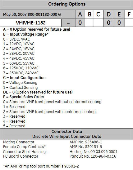
ordering information
The meaning of each parameter in the ordering options: A is a reserved option (0); B represents the input voltage range (0-7 corresponds to different AC and DC voltages); C is the input configuration (0 is voltage sensing, 1 is contact sensing); DE is a reserved option (0); F is a special sales order (0-5 corresponds to different panel configurations).
Discrete line input connector related information: The matching connector is AMP No.925486-1, the female contact point is AMP No.530151-6, the connector housing is Harting No.09 03 096 0501, the printed circuit board connector is Panduit No.120-964-033A, the AMP crimping tool model is 90301-2, and DC or AC can be selected through software.
Functional feature details
Basic functions: It can detect COS with 64 digital inputs, perform time tagging and counting. The onboard buffer can store COS information with time tags to analyze SOEs. The pulse accumulator is used to count COS. When COS is detected, it can be programmed to issue an interrupt, and each channel processes it independently.
COS timing: The input signal is latched every millisecond, and after a programmable debounce time (1.25ms-1.024s), if a valid COS is detected, it will be time marked and stored by a millisecond timer. The minimum reliable detection pulse time is 2ms.
COS detection: Programmable detection of rising edge, falling edge, or both, detecting COS can generate interrupts or disable.
Time stamping: Each COS event can be marked with a timer value of 0-65s, which updates every millisecond. When the maximum value is reached, it resets to zero and notifies the host.
Sequence of Events (SOE): SOE memory is allocated to two buffers (each capable of storing 3000 events), where the host processes one buffer while the other can load new event data. SOE logic can issue interrupts to the host at the end of the buffer or when the user sets a count.
Pulse Accumulation: Each channel has a Pulse Accumulation Count (PAC) register, and when the count reaches 65535, it will notify the user through a flag in the control register or issue an interrupt.
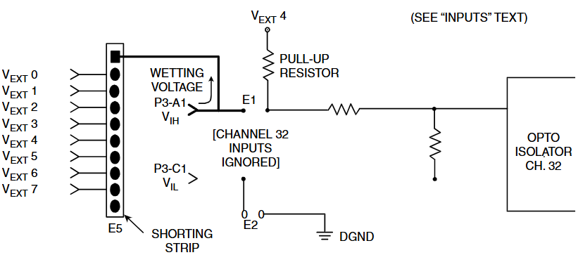
Input configuration: divided into voltage sensing and contact sensing options. The contact sensing option is equipped with a pull-up resistor to the wetting voltage pin, while the voltage source option has no pullups and has 8 wetting voltage input pins. Channel 32 can be changed to a wetting voltage supply through jumper wires.
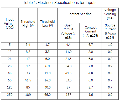
Electrical specifications
Provides high threshold, low threshold, contact induction (open circuit voltage, contact current), and voltage induction (source current) parameters corresponding to different input voltages (VDC), with a minimum inter channel crosstalk suppression of 80dB (1kHz) and a minimum common mode suppression of 80dB (DC-60Hz).
VME compliance
Compliant with the VMEbus specification (ANSI/IEEE STD 1014-1987, IEC 821 and 297), it provides response address modifiers, data access modes, and interrupt situations corresponding to different addressing modes.
Other characteristics
Board address: Set the basic VME address through jumper wires, with an address space of 8K words.
VME access: Address modifier bits are selected and decoded through jumpers, supporting non privileged, monitored, and both board access.
Self check: The system automatically runs after resetting, or it can be run by activating the test mode bit in CSR. The self check result is stored in the control register space, and the LED status does not change with the self check result. It mainly checks the integrity of the microcontroller and onboard memory.
System reset: After reset, there are default conditions such as input transmission (1ms debounce), LED lighting, and test mode activation.
Front panel status LED: It lights up after system reset and can be controlled by software switch.
Interrupt: It can be issued at any level, and after confirmation, the bus will place a single byte vector. There are multiple interrupt triggering conditions that can be enabled/disabled.
Physical/Environmental Specifications
Dimensions: Height 9.2 inches (233.4mm), Depth 6.3 inches (160mm), Thickness 0.8 inches (20.3mm).
Power requirement: Typical value of 2.0A at 5V, plus power consumption of pull-up resistor.
Cooling method: forced air cooling.
Temperature range: working 0-65 ° C, storage -25-85 ° C.
Altitude: Working at 0-10000 feet (3048m).
Humidity: Operating relative humidity of 20% -80%, non condensing.
Maximum weight: 0.7kg.
- YOKOGAWA
- Reliance
- ADVANCED
- SEW
- ProSoft
- WATLOW
- Kongsberg
- FANUC
- VSD
- DCS
- PLC
- man-machine
- Covid-19
- Energy and Gender
- Energy Access
- Renewable Integration
- Energy Subsidies
- Energy and Water
- Net zero emission
- Energy Security
- Critical Minerals
- A-B
- petroleum
- Mine scale
- Sewage treatment
- cement
- architecture
- Industrial information
- New energy
- Automobile market
- electricity
- Construction site
- HIMA
- ABB
- Rockwell
- Schneider Modicon
- Siemens
- xYCOM
- Yaskawa
- Woodward
- BOSCH Rexroth
- MOOG
- General Electric
- American NI
- Rolls-Royce
- CTI
- Honeywell
- EMERSON
- MAN
- GE
- TRICONEX
- Control Wave
- ALSTOM
- AMAT
- STUDER
- KONGSBERG
- MOTOROLA
- DANAHER MOTION
- Bentley
- Galil
- EATON
- MOLEX
- Triconex
- DEIF
- B&W
- ZYGO
- Aerotech
- DANFOSS
- KOLLMORGEN
- Beijer
- Endress+Hauser
- schneider
- Foxboro
- KB
- REXROTH
- YAMAHA
- Johnson
- Westinghouse
- WAGO
- TOSHIBA
- TEKTRONIX
- BENDER
- BMCM
- SMC
- HITACHI
- HIRSCHMANN
- XP POWER
- Baldor
- Meggitt
- SHINKAWA
- Other Brands
- UniOP
- KUKA
- IBA
- Beckhoff
- ADLINK
-
Beckhoff CX5020-0112 - PLC Module
-
Beckhoff CP2912-0000 - Control Panel
-
Beckhoff C6920-1047-0030 - industrial control cabinet control PC
-
BECKHOFF CX1020-0121 - CPU Module Power Supply Setup
-
Beckhoff EL6752 - DeviceNet Master EtherCAT Terminal
-
Beckhoff IP1002-B518 - Fieldbus Box Module
-
Beckhoff CP6606-0001-0020 - 7 inch Economy Panel PC incl. Connection Cable
-
Beckhoff CX5010-0111 - Controller Module
-
BECKHOFF AX2020-S62000-520 - SERVO DRIVE 5.76
-
Beckhoff EL1904 - 4-Channel Digital Input Module
-
BECKHOFF AX5201-0000 - Servo Drive
-
Beckhoff CP7201-1000-0000 - Industrial PC with Touch Screen
-
Beckhoff BK7350 - module Bus Coupler
-
BECKHOFF C6930-0010 - PLC PC Industrial PC
-
Beckhoff AX5125-0000 - Servo Amplifier
-
Beckhoff CX2100-0914 - Power Supply for External UPS for CX20xx
-
Beckhoff CP6608-1000-0010 - Control Panel
-
Beckhoff EL7221-9014 - EtherCAT Terminal, 1 Channel Motion Interface, 48 V DC
-
BECKHOFF CP2919-0000 - Multitouch Built-In Control Panel 24VDC 19"
-
BECKHOFF C6015-0010 - TWINCAT2 Single Core 1.46GHz Industrial PC
-
Beckhoff CU8803-0000 - Controller Module Transmitter
-
BECKHOFF CU1521-0000 - EtherCAT media converter
-
Beckhoff CX5140-0111 - Control Embedded PC HW 3.1 + Flash Card CX2900-0028 4GB
-
Beckhoff AX2513-B200 - Servo Amplifier Servodrive
-
Rexroth MSK061C-0600-NN-M1-UP1-NNNN - Engine Servo Motor
-
Beckhoff AM3031-0C01-0000 - Servo Motor
-
BECKHOFF CP7201-1000-0000 - Industrial PC with touch screen
-
BECKHOFF C6925-0000 - PLC Module Industrial PC
-
BECKHOFF EL5151-0021 - PLC module Encoder Interface
-
Beckhoff CX5130-0125-1001 - Module Embedded PC
-
BECKHOFF EP3356-0022 - EtherCAT Box Module
-
BECKHOFF AX5203-0000 - SERVO DRIVE
-
B&R X20IF1082 - COMMUNICATION INTERFACE MODULE POWER LINK
-
BECKHOFF EL7342 - PLC Module 2-Channel DC Motor Output
-
BECKHOFF CX8190 - Ethernet Controller
-
BECKHOFF CX2020-0120/4GB - CPU CX2100-0904 3x EL6900 EL1904 16GB RAM
-
Beckhoff CX5130-0112 - Module Embedded PC
-
Beckhoff CP7701-0001-0020 - Panel-PC Touch Panel 12" ELO Accutouch AMD ALX 500MHz
-
BECKHOFF CX5020-0111 - Embedded PC Controller
-
Beckhoff CX2040-0100 - Embedded PC HW: 4.0 + CX2100 0014 + 4GB CFast Card
-
Beckhoff CP6512-0001 0030 - Control Panel
-
beckhoff CX9020-0111-0900 - Controller Modules
-
Beckhoff IE3112 - Module Fieldbus Box
-
BECKHOFF CX8051 - PLC Module
-
BECKHOFF CX1100-0920 - module Power Supply
-
Beckhoff CP7921-1075-0000 - Control Panel
-
B&R 3NC352.6 - PLC Module
-
Beckhoff CX8095 - module Controller
-
beckhoff CX1020-0021 - CPU controller module
-
BECKHOFF BK9103 - PROFINET BUS COUPLER
-
Beckhoff C6930-0050 - Schaltschrank-Industrie-Pc Core i7-4700 CPU+FC9062 Modules
-
Beckhoff AM8013-0DH0-1001 - Servo Motor
-
BECKHOFF EPP3184-0002 - Module EtherCAT-P Box
-
BECKHOFF AM8041-0H10-0000 - servo motor
-
BECKHOFF CX1010-0100 - Embedded PC Module System
-
beckhoff CP2916-0000 - Industrial touch screen
-
Beckhoff C6110 - Industrial PC Boser HS6237
-
Beckhoff CX1010-0111 - CPU Module Setup
-
Beckhoff EL3751 - EtherCAT Terminal 1 Channel Analog Input Multifunction 24 Bit
-
BECKHOFF AX5721-0000 - Encoder Interface Card
-
Beckhoff CX1020-0122 - module Embedded PC
-
BECKHOFF CP3921-0000 - Control Panel
-
BECKHOFF CX2040-0155 - STANDARD CPU MODULE INTEL I7 2715QE 2.1GHz
-
BECKHOFF CX5020-0111 - Controller module
-
Beckhoff AX5201-0000-0200 - servo drive
-
BECKHOFF CP2921-0000 - Multi-touch built-in Control Panel with DVI/USB
-
BECKHOFF CP3907-0000 - Touch Panel
-
Beckhoff CX5120-0115 - CPU Module
-
Beckhoff KL3361 - PLC Module Oscilloscope Terminal
-
Beckhoff CX1000-0111 - Embedded PC System Combination
-
Beckhoff AM8023-0E20-0000 - Servo motor with Tramec EP75/2 Transmission
-
beckhoff am8533-2f10-0000 - servo motor
-
BECKHOFF EL5042 - EtherCAT Terminal
-
Beckhoff CX9001-1001 - PLC Module
-
BECKHOFF CX9020-0112 - Digital Module CPU Controller
-
BECKHOFF CP6709-0001-0000 - Touchpanel
-
Beckhoff 1004B2060000 - Communication Module
-
Beckhoff CX5020-0112 - PLC Controller
-
BECKHOFF EL2904 - EtherCAT Safety Input Output Module 24V
-
Beckhoff CX2040-0142 - Embedded PC Controller Module
-
BECKHOFF AM8121-0F20-0000 - SERVO MOTOR
-
Beckhoff CX9020-0112 - CPU Module
-
BECKHOFF CB3050-0008 - PCB Motherboard Board
-
Beckhoff EK1512-0010 - PLC Module EtherCAT Junction
-
BECKHOFF CX1001-0121 - Embedded PC And CPU Basic Module Controller
-
Beckhoff C6032-0070 - Industrial PC
-
Beckhoff CX1020-0122 - Module Embedded PC
-
BECKHOFF CX8010 - Controller Module
-
BECKHOFF EK1818 - Modules EtherCAT Bus Coupler
-
BECKHOFF CX5140-0155 - PLC Embedded PC
-
BECKHOFF CX1100-0910 - Power Supply Module
-
Beckhoff CX1001-0121 - CPU Module + CX1000-C00L + CX1100-0002 + CX1000-N001
-
Beckhoff CP6801-0001-0010 - Control Panel
-
BECKHOFF BK9103-1005 - Bus Coupler PROFINET
-
Beckhoff AX5203-0000-0202 - 161336 Digital Compact Servo Amplifier 2 Channel
-
BECKHOFF CX5020-0111 - Controller module
-
BECKHOFF CP7032-1031-0010 - Cp-Link Control Panel
-
Beckhoff AX5112-0000-0200 - Servo Driver
-
Beckhoff BX8000-0000 - RS232/RS485 Bus Terminal Controller | HW:1.4
-
BECKHOFF CX2020-0120 - CPU MODULE WITH CX2100 Power Supply
-
Beckhoff EL4012 - Module EtherCAT Terminal
-
BECKHOFF CP6204-0001-0030 - ECONOMY INSTALLATION CONTROL PANEL
-
Beckhoff CP6833-0001-0011 - Built-In Control Panel-Without Control Panel Monitor
-
BECKHOFF EK1521-0000 - module EtherCAT junction
-
Beckhoff EP3314-0002 - EtherCAT Compact Box M12 4x Analog Input Thermoelements
-
Beckhoff CX8090 - PLC modules Controller
-
Beckhoff AM8033-0JG0-0000 - Servo Motor
-
Beckhoff CP9035.2 - CP9035 capture card
-
Beckhoff CP7802-1241-0010 - Industrial Touchscreen 15 Inch
-
Beckhoff BX8000-0000 - Module Bus Terminal Controller
-
BECKHOFF IE1002-0000 - Junction box
-
Beckhoff AM237S-0021 - Servomotor
-
Beckhoff EL2564 - EtherCAT Terminal, 4-channel LED output, 5-48VDC, 4A, RGBW
-
BECKHOFF EL1918 - EtherCAT Terminal 8-Channel Digital Input 24V DC
-
Beckhoff CB3052-0005 - Circuitboard Motherboard
-
Beckhoff AM8023-2E11-0000 - Servomotor
-
Beckhoff CX8190 - Ethernet Controller
-
BECKHOFF EL4038 - Module EtherCAT Terminal
-
B&R 5PC910.SX01-00 - APC910 Industrial PC | i5-6440EQ 8GB
-
Beckhoff CP9030-A002 - CP-Link Karte Version: 1.1
-
BECKHOFF BK7200 - CTNET Control Techniques Bus Coupler
-
Beckhoff CP2616-0000 - Multi-Touch Touchscreen Panel for 24V DC Automation
-
BECKHOFF LOT 31 modules - PLC Module Bundle
-
BECKHOFF EJ2889-0000 - Module EtherCAT Plug-in Module
-
BECKHOFF AM8043-0H20-0000 - Servomotor
-
BECKHOFF EL3154 - module EtherCAT Terminal
-
Beckhoff C6017-0030 - Industrial PC
-
BECKHOFF CX9020-0112 - CPU Module

K-JIANG

Add: Jimei North Road, Jimei District, Xiamen, Fujian, China
Tell:+86-15305925923