
K-WANG


GE VMIVME-2232 32 32 channel relay output board
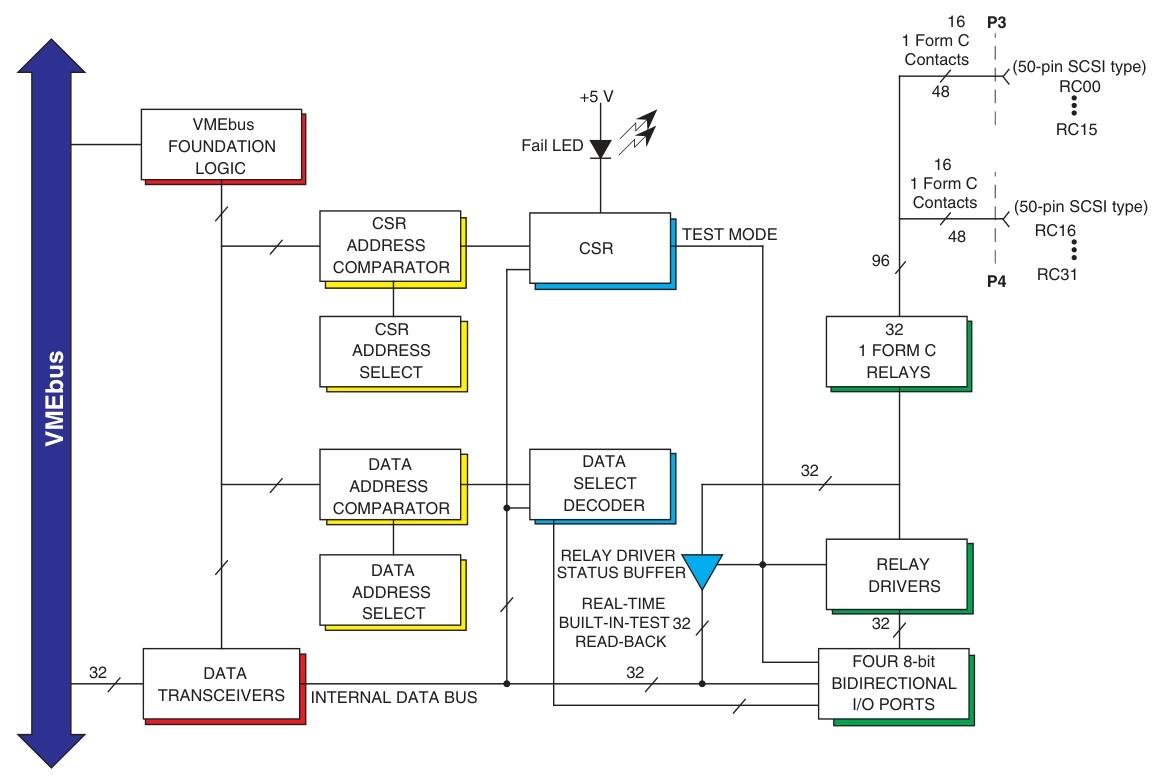
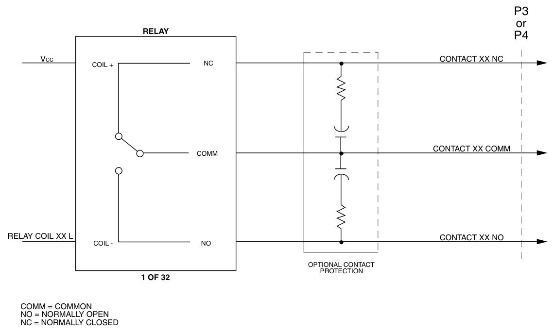
Channel configuration: 32 relay output channels, each channel containing 1 C-type relay
Compatibility: Compatible with the VMEbus specification and has a dual height appearance; Compatible with intelligent I/O controllers; Compatible with VMIVME-2532 and VMIVMME-2533 software
GE VMIVME-2232 32 32 channel relay output board
Basic Information
Product Name: VMIVME-2232 32 Channel Relay Output Board with Built in Test (BIT)
Channel configuration: 32 relay output channels, each channel containing 1 C-type relay
Compatibility: Compatible with the VMEbus specification and has a dual height appearance; Compatible with intelligent I/O controllers; Compatible with VMIVME-2532 and VMIVMME-2533 software
Relay parameters
CONTACT RATING
Maximum switching power: 60W, 125VA
Maximum switch voltage: 220VDC, 250VAC
Maximum switch current: 2A
Maximum carrying current: 3A
UL/CSA certification: 0.6A at 110VDC, 0.6A at 125VAC, 2.0A at 30VDC
Contact life (minimum number of operations)
Mechanical (at 180CPM): 10 times
Electrical: 5 × 10 ⁵ times under 2A 30VDC; 2 x 10 times at 1A 30VDC
Output specifications
Output connector type: SCSI connector, dual 50 pin compatible
Output organization: 4 8-bit wide ports
Built in testing (BIT) function
Test mode activation scenario: software control, onboard power on, after system reset
Test mode features: Relay driver disabled (safety precautions), special test data can be written and read back to test the data path to the relay driver, and the read back data is real data (non inverted)
Non testing mode (online operation)
Positive logic board: When the data bit of the corresponding relay in the data register is set to a specific logic, the relay is activated (normally open contact closed)
Negative logic board: When the data bit of the corresponding relay in the data register is set to a specific logic, the relay is activated
Read back data characteristics: The read back function of the output register is disabled, and the read back data is inverted data
Power on and reset states: configured as test mode, all data registers are in a specific logic state; For negative logic options, data initialization is required before removing the test mode condition, otherwise all relays will be activated
General specifications
Data transmission: Supports 8-bit, 16 bit, or 32-bit data transmission
Address scheme: Four ports can be addressed with 8-bit, 16 bit, or 32-bit boundaries in short I/O addressing, and accessed as corresponding bit width words
Address modifier code: Short monitoring and/or short non privileged I/O access can be selected through jumper, factory configured for short monitoring I/O access
Control and Status Register (CSR): Used to control the front panel fault LED, internal built-in testing functions, and enable/disable relays
Board address: Select jumper in short I/O memory mapping through address selection
Front panel: equipped with a fault LED, which lights up when powered on and can be controlled to turn off through a program
Physical/Environmental Parameters
Temperature: Operating temperature 0-55 ° C; Storage temperature -40-85 ° C
Humidity: 20% -80%, no condensation
Altitude: The working altitude can reach 10000 feet
Cooling method: forced air convection
Power requirement: 3.9A at+5V
Mean Time Between Failures (MTBF): 70540 hours (217F standard)
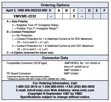
Ordering Options
Data polarity (A): 0 is negative logic ("0" excites the relay); 1 is positive logic ("1" excites the relay)
Contact protection (B): 0 indicates no protection; 1 is a contact protection suitable for 1A switch current, maximum 50VDC (R=5.6 Ω, C=0.1 µ F)
Other options: C=0 is a reserved option for the future; 2 is a contact protection suitable for 1A switch current and maximum 200VDC (R=22 Ω, C=0.1 µ F)
Connectors: The PC board connectors are AMP 554085-1 and AMP 554901
- YOKOGAWA
- Reliance
- ADVANCED
- SEW
- ProSoft
- WATLOW
- Kongsberg
- FANUC
- VSD
- DCS
- PLC
- man-machine
- Covid-19
- Energy and Gender
- Energy Access
- Renewable Integration
- Energy Subsidies
- Energy and Water
- Net zero emission
- Energy Security
- Critical Minerals
- A-B
- petroleum
- Mine scale
- Sewage treatment
- cement
- architecture
- Industrial information
- New energy
- Automobile market
- electricity
- Construction site
- HIMA
- ABB
- Rockwell
- Schneider Modicon
- Siemens
- xYCOM
- Yaskawa
- Woodward
- BOSCH Rexroth
- MOOG
- General Electric
- American NI
- Rolls-Royce
- CTI
- Honeywell
- EMERSON
- MAN
- GE
- TRICONEX
- Control Wave
- ALSTOM
- AMAT
- STUDER
- KONGSBERG
- MOTOROLA
- DANAHER MOTION
- Bentley
- Galil
- EATON
- MOLEX
- Triconex
- DEIF
- B&W
- ZYGO
- Aerotech
- DANFOSS
- KOLLMORGEN
- Beijer
- Endress+Hauser
- schneider
- Foxboro
- KB
- REXROTH
- YAMAHA
- Johnson
- Westinghouse
- WAGO
- TOSHIBA
- TEKTRONIX
- BENDER
- BMCM
- SMC
- HITACHI
- HIRSCHMANN
- XP POWER
- Baldor
- Meggitt
- SHINKAWA
- Other Brands
- UniOP
- KUKA
- IBA
- Beckhoff
- ADLINK
-
Beckhoff CX5020-0112 - PLC Module
-
Beckhoff CP2912-0000 - Control Panel
-
Beckhoff C6920-1047-0030 - industrial control cabinet control PC
-
BECKHOFF CX1020-0121 - CPU Module Power Supply Setup
-
Beckhoff EL6752 - DeviceNet Master EtherCAT Terminal
-
Beckhoff IP1002-B518 - Fieldbus Box Module
-
Beckhoff CP6606-0001-0020 - 7 inch Economy Panel PC incl. Connection Cable
-
Beckhoff CX5010-0111 - Controller Module
-
BECKHOFF AX2020-S62000-520 - SERVO DRIVE 5.76
-
Beckhoff EL1904 - 4-Channel Digital Input Module
-
BECKHOFF AX5201-0000 - Servo Drive
-
Beckhoff CP7201-1000-0000 - Industrial PC with Touch Screen
-
Beckhoff BK7350 - module Bus Coupler
-
BECKHOFF C6930-0010 - PLC PC Industrial PC
-
Beckhoff AX5125-0000 - Servo Amplifier
-
Beckhoff CX2100-0914 - Power Supply for External UPS for CX20xx
-
Beckhoff CP6608-1000-0010 - Control Panel
-
Beckhoff EL7221-9014 - EtherCAT Terminal, 1 Channel Motion Interface, 48 V DC
-
BECKHOFF CP2919-0000 - Multitouch Built-In Control Panel 24VDC 19"
-
BECKHOFF C6015-0010 - TWINCAT2 Single Core 1.46GHz Industrial PC
-
Beckhoff CU8803-0000 - Controller Module Transmitter
-
BECKHOFF CU1521-0000 - EtherCAT media converter
-
Beckhoff CX5140-0111 - Control Embedded PC HW 3.1 + Flash Card CX2900-0028 4GB
-
Beckhoff AX2513-B200 - Servo Amplifier Servodrive
-
Rexroth MSK061C-0600-NN-M1-UP1-NNNN - Engine Servo Motor
-
Beckhoff AM3031-0C01-0000 - Servo Motor
-
BECKHOFF CP7201-1000-0000 - Industrial PC with touch screen
-
BECKHOFF C6925-0000 - PLC Module Industrial PC
-
BECKHOFF EL5151-0021 - PLC module Encoder Interface
-
Beckhoff CX5130-0125-1001 - Module Embedded PC
-
BECKHOFF EP3356-0022 - EtherCAT Box Module
-
BECKHOFF AX5203-0000 - SERVO DRIVE
-
B&R X20IF1082 - COMMUNICATION INTERFACE MODULE POWER LINK
-
BECKHOFF EL7342 - PLC Module 2-Channel DC Motor Output
-
BECKHOFF CX8190 - Ethernet Controller
-
BECKHOFF CX2020-0120/4GB - CPU CX2100-0904 3x EL6900 EL1904 16GB RAM
-
Beckhoff CX5130-0112 - Module Embedded PC
-
Beckhoff CP7701-0001-0020 - Panel-PC Touch Panel 12" ELO Accutouch AMD ALX 500MHz
-
BECKHOFF CX5020-0111 - Embedded PC Controller
-
Beckhoff CX2040-0100 - Embedded PC HW: 4.0 + CX2100 0014 + 4GB CFast Card
-
Beckhoff CP6512-0001 0030 - Control Panel
-
beckhoff CX9020-0111-0900 - Controller Modules
-
Beckhoff IE3112 - Module Fieldbus Box
-
BECKHOFF CX8051 - PLC Module
-
BECKHOFF CX1100-0920 - module Power Supply
-
Beckhoff CP7921-1075-0000 - Control Panel
-
B&R 3NC352.6 - PLC Module
-
Beckhoff CX8095 - module Controller
-
beckhoff CX1020-0021 - CPU controller module
-
BECKHOFF BK9103 - PROFINET BUS COUPLER
-
Beckhoff C6930-0050 - Schaltschrank-Industrie-Pc Core i7-4700 CPU+FC9062 Modules
-
Beckhoff AM8013-0DH0-1001 - Servo Motor
-
BECKHOFF EPP3184-0002 - Module EtherCAT-P Box
-
BECKHOFF AM8041-0H10-0000 - servo motor
-
BECKHOFF CX1010-0100 - Embedded PC Module System
-
beckhoff CP2916-0000 - Industrial touch screen
-
Beckhoff C6110 - Industrial PC Boser HS6237
-
Beckhoff CX1010-0111 - CPU Module Setup
-
Beckhoff EL3751 - EtherCAT Terminal 1 Channel Analog Input Multifunction 24 Bit
-
BECKHOFF AX5721-0000 - Encoder Interface Card
-
Beckhoff CX1020-0122 - module Embedded PC
-
BECKHOFF CP3921-0000 - Control Panel
-
BECKHOFF CX2040-0155 - STANDARD CPU MODULE INTEL I7 2715QE 2.1GHz
-
BECKHOFF CX5020-0111 - Controller module
-
Beckhoff AX5201-0000-0200 - servo drive
-
BECKHOFF CP2921-0000 - Multi-touch built-in Control Panel with DVI/USB
-
BECKHOFF CP3907-0000 - Touch Panel
-
Beckhoff CX5120-0115 - CPU Module
-
Beckhoff KL3361 - PLC Module Oscilloscope Terminal
-
Beckhoff CX1000-0111 - Embedded PC System Combination
-
Beckhoff AM8023-0E20-0000 - Servo motor with Tramec EP75/2 Transmission
-
beckhoff am8533-2f10-0000 - servo motor
-
BECKHOFF EL5042 - EtherCAT Terminal
-
Beckhoff CX9001-1001 - PLC Module
-
BECKHOFF CX9020-0112 - Digital Module CPU Controller
-
BECKHOFF CP6709-0001-0000 - Touchpanel
-
Beckhoff 1004B2060000 - Communication Module
-
Beckhoff CX5020-0112 - PLC Controller
-
BECKHOFF EL2904 - EtherCAT Safety Input Output Module 24V
-
Beckhoff CX2040-0142 - Embedded PC Controller Module
-
BECKHOFF AM8121-0F20-0000 - SERVO MOTOR
-
Beckhoff CX9020-0112 - CPU Module
-
BECKHOFF CB3050-0008 - PCB Motherboard Board
-
Beckhoff EK1512-0010 - PLC Module EtherCAT Junction
-
BECKHOFF CX1001-0121 - Embedded PC And CPU Basic Module Controller
-
Beckhoff C6032-0070 - Industrial PC
-
Beckhoff CX1020-0122 - Module Embedded PC
-
BECKHOFF CX8010 - Controller Module
-
BECKHOFF EK1818 - Modules EtherCAT Bus Coupler
-
BECKHOFF CX5140-0155 - PLC Embedded PC
-
BECKHOFF CX1100-0910 - Power Supply Module
-
Beckhoff CX1001-0121 - CPU Module + CX1000-C00L + CX1100-0002 + CX1000-N001
-
Beckhoff CP6801-0001-0010 - Control Panel
-
BECKHOFF BK9103-1005 - Bus Coupler PROFINET
-
Beckhoff AX5203-0000-0202 - 161336 Digital Compact Servo Amplifier 2 Channel
-
BECKHOFF CX5020-0111 - Controller module
-
BECKHOFF CP7032-1031-0010 - Cp-Link Control Panel
-
Beckhoff AX5112-0000-0200 - Servo Driver
-
Beckhoff BX8000-0000 - RS232/RS485 Bus Terminal Controller | HW:1.4
-
BECKHOFF CX2020-0120 - CPU MODULE WITH CX2100 Power Supply
-
Beckhoff EL4012 - Module EtherCAT Terminal
-
BECKHOFF CP6204-0001-0030 - ECONOMY INSTALLATION CONTROL PANEL
-
Beckhoff CP6833-0001-0011 - Built-In Control Panel-Without Control Panel Monitor
-
BECKHOFF EK1521-0000 - module EtherCAT junction
-
Beckhoff EP3314-0002 - EtherCAT Compact Box M12 4x Analog Input Thermoelements
-
Beckhoff CX8090 - PLC modules Controller
-
Beckhoff AM8033-0JG0-0000 - Servo Motor
-
Beckhoff CP9035.2 - CP9035 capture card
-
Beckhoff CP7802-1241-0010 - Industrial Touchscreen 15 Inch
-
Beckhoff BX8000-0000 - Module Bus Terminal Controller
-
BECKHOFF IE1002-0000 - Junction box
-
Beckhoff AM237S-0021 - Servomotor
-
Beckhoff EL2564 - EtherCAT Terminal, 4-channel LED output, 5-48VDC, 4A, RGBW
-
BECKHOFF EL1918 - EtherCAT Terminal 8-Channel Digital Input 24V DC
-
Beckhoff CB3052-0005 - Circuitboard Motherboard
-
Beckhoff AM8023-2E11-0000 - Servomotor
-
Beckhoff CX8190 - Ethernet Controller
-
BECKHOFF EL4038 - Module EtherCAT Terminal
-
B&R 5PC910.SX01-00 - APC910 Industrial PC | i5-6440EQ 8GB
-
Beckhoff CP9030-A002 - CP-Link Karte Version: 1.1
-
BECKHOFF BK7200 - CTNET Control Techniques Bus Coupler
-
Beckhoff CP2616-0000 - Multi-Touch Touchscreen Panel for 24V DC Automation
-
BECKHOFF LOT 31 modules - PLC Module Bundle
-
BECKHOFF EJ2889-0000 - Module EtherCAT Plug-in Module
-
BECKHOFF AM8043-0H20-0000 - Servomotor
-
BECKHOFF EL3154 - module EtherCAT Terminal
-
Beckhoff C6017-0030 - Industrial PC
-
BECKHOFF CX9020-0112 - CPU Module

K-JIANG

Add: Jimei North Road, Jimei District, Xiamen, Fujian, China
Tell:+86-15305925923