
K-WANG


GE VMIVME-4514A 16 channel scanning analog I/O board
GE VMIVME-4514A 16 channel scanning analog I/O board
Product Overview
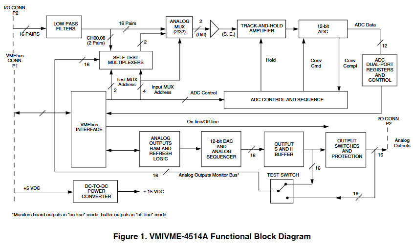
VMIVME-4514A is a 16 channel scanning analog I/O board with built-in testing capabilities and P2 I/O connections. It provides 16 analog output channels and 16 analog input channels, with both input and output resolutions of 12 bits. Each channel of the analog output is designed with a sample and hold (S&H) output, and 16 analog inputs are digitized by a 12 bit analog-to-digital converter (ADC) controlled by a scanner, which can store data in dual port memory.
Core functions and features
Main functions
Continuously digitize all input channels and store the results in dedicated channel dual port registers (automatic scanning mode).
It has three A/D operation modes: automatic scanning mode when powered on, random polarization mode, and scanning polarization mode.
Supports P2 I/O connection, built-in onboard testing function, capable of testing 100% of active components.
Using semiconductor output switches does not affect accuracy (output impedance 0.1 Ω).
Analog input characteristics
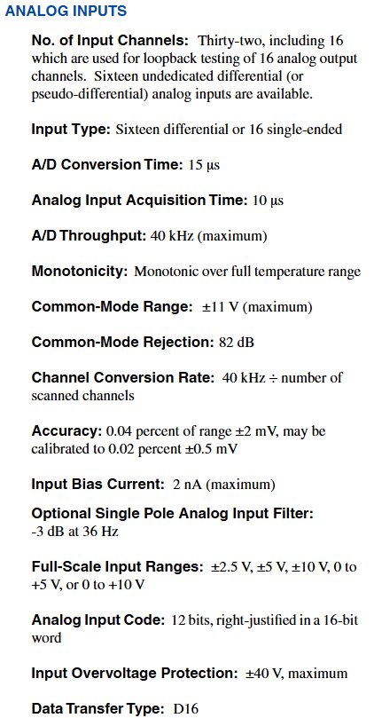
16 single ended/differential (SE/Diff) analog input channels, 12 bit A/D converter.
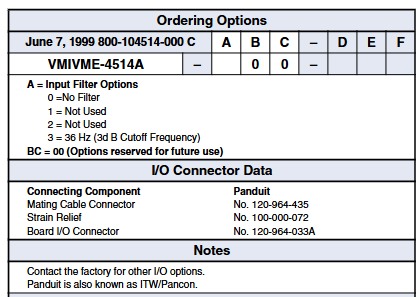
Supports unipolar (0 to+10 V, 0 to+5 V) or bipolar (± 2.5 V, ± 5 V, ± 10 V) inputs.
A/D throughput of 40 kHz, optional low-pass filter, with overvoltage protection function.
Input relevant parameters: A/D conversion time of 15 µ s, acquisition time of 10 µ s, common mode range of ± 11 V (maximum), common mode rejection ratio of 82 dB, maximum input bias current of 2 nA, overvoltage protection of ± 40 V (maximum), data transmission type of D16.
Accuracy: 0.04% range ± 2 mV, can be calibrated to 0.02% ± 0.5 mV.
Analog output characteristics
16 sample and hold (S&H) analog output channels, 12 bit D/A converter.
The output has short-circuit protection and supports unipolar (0 to+10 V, 0 to 5 V) or bipolar (± 2.5 V, ± 5 V, ± 10 V) output.
The program can choose a scanning rate to provide better response for complex output functions, with an output current of 10 mA.
Output related parameters: resolution of 12 bits (per channel S&H), output impedance of 0.1 Ω, total error of 0.05% of full-scale range, and maximum setup time of 1.7 ms to reach 1 LSB.
Refresh update rate: default 550 Hz, fast refresh 1600 Hz (note: output refresh temporarily stops during input analog-to-digital conversion, so the output refresh rate decreases with the increase of analog-to-digital conversion rate. In the worst case scenario of automatic scanning mode, the default refresh rate is 300 Hz, and fast refresh is 900 Hz).
Operation Mode
Automatic scanning mode: Through power on system reset or program selection execution, all channels are continuously scanned, and digital data is stored in 16 16 bit dual port registers. It only needs to be read from the dual port registers without further programming.
Random polling mode: It is necessary to control the program to generate a single transition, and determine whether the transition is completed through the polling transition end status bit.
Scanning polarization mode: Perform a single scan of all channels, and determine whether the scan is complete through the polarization scan end control bit.
Other Features
Board address and VMEbus access
The physical address of the board can be selected through jumper wires on the board, and decoding the VMEbus address lines A06 to A15 is used for board selection.
The address modification bit is selected and decoded through jumper wires, supporting non privileged short I/O, monitoring short I/O, or both. The factory is configured to monitor short I/O.
Data transmission and format
Output data transmission: The data of each analog output channel is directly written to the RAM location dedicated to a specific channel on the board, and then periodically retrieved from the RAM and converted into analog voltage, which is transmitted to one of the 16 output sample and hold buffers.
Analog input format: The analog input is first digitized, and then the 12 bit digital value (D11 to D00) is read from a single storage word position in the channel specific dual port register. In binary complement mode, the high four bits (D15, D14, D13, D12) are read as sign extensions of the 12 bit digital value, otherwise they are read as logical zeros.
Testing and Resetting
Simulated I/O testing mode: Built in testing logic supports testing all active components (including output switches) on the board, supports real-time and offline testing, and utilizes the ADC multiplexer on the board.
Memory testing: Designed with onboard dual port memory, additional operational verification can be performed by performing memory diagnostics.
System reset: Initialize the board to a state where all analog outputs and output connectors (P2) are disconnected through the VMEbus application system reset signal.
Front panel malfunction LED
If an error occurs during the diagnostic process, the software controlled LED will light up to visually indicate the fault. The LED will be reset and lit by the system during power up, and will turn off after successful diagnosis.
Bus interface and physical environment characteristics
Bus interface compatibility: Compliant with VMEbus specification Rev. C. 1, with features such as A16:29, 2D: D16, D08 (EO) (slave), and 6U external specifications.
Physical characteristics: Standard VME double width board, size 160 × 233.5 mm.
Environmental characteristics: Operating temperature from 0 to 55 ° C, storage temperature from -40 to+85 ° C, relative humidity from 20 to 80% (non condensing), using convection cooling.
Power requirements:+5 VDC (± 5%), maximum 5.6 A, typical 3.0 A.
Connector: Standard P2 user I/O (with extended ground pins on P1 and P2).
Mean Time Between Failures (MTBF): 29800 hours (217F).
Application field
Including factory automation and instrumentation, process control, laboratory instruments, machine monitoring, data acquisition systems, simulation and training, etc.
- YOKOGAWA
- Reliance
- ADVANCED
- SEW
- ProSoft
- WATLOW
- Kongsberg
- FANUC
- VSD
- DCS
- PLC
- man-machine
- Covid-19
- Energy and Gender
- Energy Access
- Renewable Integration
- Energy Subsidies
- Energy and Water
- Net zero emission
- Energy Security
- Critical Minerals
- A-B
- petroleum
- Mine scale
- Sewage treatment
- cement
- architecture
- Industrial information
- New energy
- Automobile market
- electricity
- Construction site
- HIMA
- ABB
- Rockwell
- Schneider Modicon
- Siemens
- xYCOM
- Yaskawa
- Woodward
- BOSCH Rexroth
- MOOG
- General Electric
- American NI
- Rolls-Royce
- CTI
- Honeywell
- EMERSON
- MAN
- GE
- TRICONEX
- Control Wave
- ALSTOM
- AMAT
- STUDER
- KONGSBERG
- MOTOROLA
- DANAHER MOTION
- Bentley
- Galil
- EATON
- MOLEX
- Triconex
- DEIF
- B&W
- ZYGO
- Aerotech
- DANFOSS
- KOLLMORGEN
- Beijer
- Endress+Hauser
- schneider
- Foxboro
- KB
- REXROTH
- YAMAHA
- Johnson
- Westinghouse
- WAGO
- TOSHIBA
- TEKTRONIX
- BENDER
- BMCM
- SMC
- HITACHI
- HIRSCHMANN
- XP POWER
- Baldor
- Meggitt
- SHINKAWA
- Other Brands
- UniOP
- KUKA
- IBA
- Beckhoff
- ADLINK
-
Beckhoff CX5020-0112 - PLC Module
-
Beckhoff CP2912-0000 - Control Panel
-
Beckhoff C6920-1047-0030 - industrial control cabinet control PC
-
BECKHOFF CX1020-0121 - CPU Module Power Supply Setup
-
Beckhoff EL6752 - DeviceNet Master EtherCAT Terminal
-
Beckhoff IP1002-B518 - Fieldbus Box Module
-
Beckhoff CP6606-0001-0020 - 7 inch Economy Panel PC incl. Connection Cable
-
Beckhoff CX5010-0111 - Controller Module
-
BECKHOFF AX2020-S62000-520 - SERVO DRIVE 5.76
-
Beckhoff EL1904 - 4-Channel Digital Input Module
-
BECKHOFF AX5201-0000 - Servo Drive
-
Beckhoff CP7201-1000-0000 - Industrial PC with Touch Screen
-
Beckhoff BK7350 - module Bus Coupler
-
BECKHOFF C6930-0010 - PLC PC Industrial PC
-
Beckhoff AX5125-0000 - Servo Amplifier
-
Beckhoff CX2100-0914 - Power Supply for External UPS for CX20xx
-
Beckhoff CP6608-1000-0010 - Control Panel
-
Beckhoff EL7221-9014 - EtherCAT Terminal, 1 Channel Motion Interface, 48 V DC
-
BECKHOFF CP2919-0000 - Multitouch Built-In Control Panel 24VDC 19"
-
BECKHOFF C6015-0010 - TWINCAT2 Single Core 1.46GHz Industrial PC
-
Beckhoff CU8803-0000 - Controller Module Transmitter
-
BECKHOFF CU1521-0000 - EtherCAT media converter
-
Beckhoff CX5140-0111 - Control Embedded PC HW 3.1 + Flash Card CX2900-0028 4GB
-
Beckhoff AX2513-B200 - Servo Amplifier Servodrive
-
Rexroth MSK061C-0600-NN-M1-UP1-NNNN - Engine Servo Motor
-
Beckhoff AM3031-0C01-0000 - Servo Motor
-
BECKHOFF CP7201-1000-0000 - Industrial PC with touch screen
-
BECKHOFF C6925-0000 - PLC Module Industrial PC
-
BECKHOFF EL5151-0021 - PLC module Encoder Interface
-
Beckhoff CX5130-0125-1001 - Module Embedded PC
-
BECKHOFF EP3356-0022 - EtherCAT Box Module
-
BECKHOFF AX5203-0000 - SERVO DRIVE
-
B&R X20IF1082 - COMMUNICATION INTERFACE MODULE POWER LINK
-
BECKHOFF EL7342 - PLC Module 2-Channel DC Motor Output
-
BECKHOFF CX8190 - Ethernet Controller
-
BECKHOFF CX2020-0120/4GB - CPU CX2100-0904 3x EL6900 EL1904 16GB RAM
-
Beckhoff CX5130-0112 - Module Embedded PC
-
Beckhoff CP7701-0001-0020 - Panel-PC Touch Panel 12" ELO Accutouch AMD ALX 500MHz
-
BECKHOFF CX5020-0111 - Embedded PC Controller
-
Beckhoff CX2040-0100 - Embedded PC HW: 4.0 + CX2100 0014 + 4GB CFast Card
-
Beckhoff CP6512-0001 0030 - Control Panel
-
beckhoff CX9020-0111-0900 - Controller Modules
-
Beckhoff IE3112 - Module Fieldbus Box
-
BECKHOFF CX8051 - PLC Module
-
BECKHOFF CX1100-0920 - module Power Supply
-
Beckhoff CP7921-1075-0000 - Control Panel
-
B&R 3NC352.6 - PLC Module
-
Beckhoff CX8095 - module Controller
-
beckhoff CX1020-0021 - CPU controller module
-
BECKHOFF BK9103 - PROFINET BUS COUPLER
-
Beckhoff C6930-0050 - Schaltschrank-Industrie-Pc Core i7-4700 CPU+FC9062 Modules
-
Beckhoff AM8013-0DH0-1001 - Servo Motor
-
BECKHOFF EPP3184-0002 - Module EtherCAT-P Box
-
BECKHOFF AM8041-0H10-0000 - servo motor
-
BECKHOFF CX1010-0100 - Embedded PC Module System
-
beckhoff CP2916-0000 - Industrial touch screen
-
Beckhoff C6110 - Industrial PC Boser HS6237
-
Beckhoff CX1010-0111 - CPU Module Setup
-
Beckhoff EL3751 - EtherCAT Terminal 1 Channel Analog Input Multifunction 24 Bit
-
BECKHOFF AX5721-0000 - Encoder Interface Card
-
Beckhoff CX1020-0122 - module Embedded PC
-
BECKHOFF CP3921-0000 - Control Panel
-
BECKHOFF CX2040-0155 - STANDARD CPU MODULE INTEL I7 2715QE 2.1GHz
-
BECKHOFF CX5020-0111 - Controller module
-
Beckhoff AX5201-0000-0200 - servo drive
-
BECKHOFF CP2921-0000 - Multi-touch built-in Control Panel with DVI/USB
-
BECKHOFF CP3907-0000 - Touch Panel
-
Beckhoff CX5120-0115 - CPU Module
-
Beckhoff KL3361 - PLC Module Oscilloscope Terminal
-
Beckhoff CX1000-0111 - Embedded PC System Combination
-
Beckhoff AM8023-0E20-0000 - Servo motor with Tramec EP75/2 Transmission
-
beckhoff am8533-2f10-0000 - servo motor
-
BECKHOFF EL5042 - EtherCAT Terminal
-
Beckhoff CX9001-1001 - PLC Module
-
BECKHOFF CX9020-0112 - Digital Module CPU Controller
-
BECKHOFF CP6709-0001-0000 - Touchpanel
-
Beckhoff 1004B2060000 - Communication Module
-
Beckhoff CX5020-0112 - PLC Controller
-
BECKHOFF EL2904 - EtherCAT Safety Input Output Module 24V
-
Beckhoff CX2040-0142 - Embedded PC Controller Module
-
BECKHOFF AM8121-0F20-0000 - SERVO MOTOR
-
Beckhoff CX9020-0112 - CPU Module
-
BECKHOFF CB3050-0008 - PCB Motherboard Board
-
Beckhoff EK1512-0010 - PLC Module EtherCAT Junction
-
BECKHOFF CX1001-0121 - Embedded PC And CPU Basic Module Controller
-
Beckhoff C6032-0070 - Industrial PC
-
Beckhoff CX1020-0122 - Module Embedded PC
-
BECKHOFF CX8010 - Controller Module
-
BECKHOFF EK1818 - Modules EtherCAT Bus Coupler
-
BECKHOFF CX5140-0155 - PLC Embedded PC
-
BECKHOFF CX1100-0910 - Power Supply Module
-
Beckhoff CX1001-0121 - CPU Module + CX1000-C00L + CX1100-0002 + CX1000-N001
-
Beckhoff CP6801-0001-0010 - Control Panel
-
BECKHOFF BK9103-1005 - Bus Coupler PROFINET
-
Beckhoff AX5203-0000-0202 - 161336 Digital Compact Servo Amplifier 2 Channel
-
BECKHOFF CX5020-0111 - Controller module
-
BECKHOFF CP7032-1031-0010 - Cp-Link Control Panel
-
Beckhoff AX5112-0000-0200 - Servo Driver
-
Beckhoff BX8000-0000 - RS232/RS485 Bus Terminal Controller | HW:1.4
-
BECKHOFF CX2020-0120 - CPU MODULE WITH CX2100 Power Supply
-
Beckhoff EL4012 - Module EtherCAT Terminal
-
BECKHOFF CP6204-0001-0030 - ECONOMY INSTALLATION CONTROL PANEL
-
Beckhoff CP6833-0001-0011 - Built-In Control Panel-Without Control Panel Monitor
-
BECKHOFF EK1521-0000 - module EtherCAT junction
-
Beckhoff EP3314-0002 - EtherCAT Compact Box M12 4x Analog Input Thermoelements
-
Beckhoff CX8090 - PLC modules Controller
-
Beckhoff AM8033-0JG0-0000 - Servo Motor
-
Beckhoff CP9035.2 - CP9035 capture card
-
Beckhoff CP7802-1241-0010 - Industrial Touchscreen 15 Inch
-
Beckhoff BX8000-0000 - Module Bus Terminal Controller
-
BECKHOFF IE1002-0000 - Junction box
-
Beckhoff AM237S-0021 - Servomotor
-
Beckhoff EL2564 - EtherCAT Terminal, 4-channel LED output, 5-48VDC, 4A, RGBW
-
BECKHOFF EL1918 - EtherCAT Terminal 8-Channel Digital Input 24V DC
-
Beckhoff CB3052-0005 - Circuitboard Motherboard
-
Beckhoff AM8023-2E11-0000 - Servomotor
-
Beckhoff CX8190 - Ethernet Controller
-
BECKHOFF EL4038 - Module EtherCAT Terminal
-
B&R 5PC910.SX01-00 - APC910 Industrial PC | i5-6440EQ 8GB
-
Beckhoff CP9030-A002 - CP-Link Karte Version: 1.1
-
BECKHOFF BK7200 - CTNET Control Techniques Bus Coupler
-
Beckhoff CP2616-0000 - Multi-Touch Touchscreen Panel for 24V DC Automation
-
BECKHOFF LOT 31 modules - PLC Module Bundle
-
BECKHOFF EJ2889-0000 - Module EtherCAT Plug-in Module
-
BECKHOFF AM8043-0H20-0000 - Servomotor
-
BECKHOFF EL3154 - module EtherCAT Terminal
-
Beckhoff C6017-0030 - Industrial PC
-
BECKHOFF CX9020-0112 - CPU Module

K-JIANG

Add: Jimei North Road, Jimei District, Xiamen, Fujian, China
Tell:+86-15305925923