
K-WANG


Zygo Mark II 4-inch interferometer system
Video monitor: Display real-time interference patterns collected by the host, 9-inch diagonal screen, equipped with a universal bracket, can be placed on the desktop or installed above the host through a dedicated lifting bracket, supporting flexible adjustment of viewing angle to optimize observation effect.
Optional VP-2 video printer: uses specially coated paper to provide hard copy recording of interference fringe patterns for easy archiving and analysis.
Zygo Mark II 4-inch interferometer system
System composition and technical parameters
(1) System core module
Mark II host: The core function is to collect real-time interference patterns, including a 632.8nm circularly polarized output HeNe laser (replaceable on site), laser power supply, beam splitter spatial filter (BDSF), CCTV camera, and a sealed optical cabin to protect precision optical components. It is equipped with accessory sockets (for installing transmission components) and a remote control box (connected by cables).
Video monitor: Display real-time interference patterns collected by the host, 9-inch diagonal screen, equipped with a universal bracket, can be placed on the desktop or installed above the host through a dedicated lifting bracket, supporting flexible adjustment of viewing angle to optimize observation effect.
Optional VP-2 video printer: uses specially coated paper to provide hard copy recording of interference fringe patterns for easy archiving and analysis.
(2) Key technical parameters
Specific parameters of the module
Mark II host aperture: 4-inch diameter, capable of continuous zoom up to 2/3 inch (6x zoom range); Alignment: Automatic alignment and fast stripe acquisition system; Video output: 520 lines/60Hz (EIA RS170 standard) or 625 lines/50Hz (CCIR standard), 2:1 interlaced scanning, BNC interface, synchronous signal including horizontal and vertical; Dimensions: 648mm x 533mm x 203mm (length x width x height); Weight: 34kg; Power supply: 115 ± 10VAC/60Hz, 110 ± 10VAC/50Hz, or 230 ± 10VAC/50Hz, 50W without monitor, 85W with monitor (single-phase)
Video monitor screen: 9-inch diagonal; Interface: BNC type; Synchronization: Built in; Video input: Supports 75 Ω or high impedance terminals; Power supply: 115 ± 10VAC/60Hz, 300mA; Dimensions: 311mm x 229mm x 241mm (length x width x height); Weight: 6.35kg
Laser Radiation Safety Regulations
Laser characteristics and risk warning: The host emits visible red light, with no harmful invisible radiation. The radiation power is less than 1 milliwatt (1/1000 watt), the wavelength is 632.8nm, and the irradiation time exceeds 0.25 seconds. It cannot burn or drill holes, but it is necessary to avoid direct viewing of the beam and strong light reflection to prevent eye damage. Skin contact is not harmful.
Classification and compliance standards: Complies with ANSI Z136.1-1980 standard and belongs to "low-power Class II laser"; Comply with the regulations of the National Center for Devices and Radiological Health (NCDRH) under the US Food and Drug Administration (FDA) effective August 2, 1976 (for laser products manufactured after August 1, 1976), and meet the DHHS radiation performance standards (21CFR Chapter 1, Subcapter J).
Safe operation and identification
Control usage: Only operate control buttons, adjust parameters, or execute procedures as specified in the manual. Violation may result in hazardous radiation exposure.
Key components: The front panel of the host has a green radiation emission indicator light (which lights up when turned on and indicates Class II radiation), and a "BEAM ATTEN." beam attenuation knob (pull out to turn off the laser, push in to turn on); The laser head and power supply need to use Zygo original accessories, and replacement should follow the process outlined in Service Manual SP-0038 to ensure compliance with federal radiation standards.
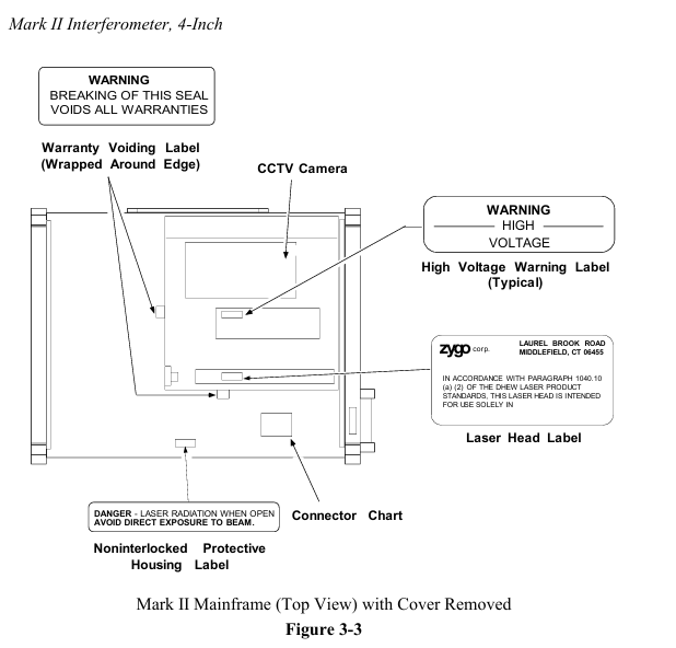
Identification location: There are certification and patent labels (US Patent No. 4201473) and model serial number labels on the back of the host; At the top (when installing the aperture converter), there is a sign that reads "Laser radiation is emitted from this aperture to avoid exposure"; After opening the lid, there are labels such as "Damaged Seal Invalid Warranty", "High Voltage Warning", "Laser Radiation When Opening, Avoid Direct Exposure" (see Figures 3-1 to 3-3).
Unpacking and installation setup
(1) Installation environment and equipment placement
Stability requirement: The host is recommended to be placed on an optical workbench (such as a granite or honeycomb air cushion platform), with a horizontal beam emitted from the right side of the equipment, making it easy to place the test piece and auxiliary components on the same platform and flexibly adapting to various testing scenarios.
Installation flexibility: In addition to the standard horizontal beam setup, the host can be installed with vertical upward/downward light output; The remote control box and movable monitor enable the host position to be optimized independently of the testing setup, suitable for laboratory prototype development, production testing, and other scenarios. It can also support multiple sets of testing setups on one host through the use of a MUX cube or mobile host.
(2) Unpacking and Inspection
System inventory: The packaging box should include the host, video monitor with bracket, lifting bracket and accessories (hardware, monitor power cord, BNC coaxial line), "Interference Pattern Interpretation and Evaluation Manual" (including mechanical parallelogram), acquisition target, "Operation and Maintenance Manual OMP-0055", "Service Manual SP-0038"; If the packaging box is damaged, please contact the shipping party immediately.
Unpacking operation: Unpacking in a clean and dry area requires two people to lift the main unit from the bottom of both ends and remove it. It is forbidden to pull or tug on the outer shell; Before removing all items, do not discard reusable packaging boxes (it is recommended to keep them for return); Cushioning materials such as foam shall be used to prevent shock during handling to avoid severe impact.
(3) Connection and switch settings
Cable connection: Connect the BNC cable according to Figure 4-1 (host monitor) and Figure 4-2 (host monitor printer); The default factory setting for the CCTV camera jumper in the host is "output synchronization", which does not require adjustment.
Power and parameters: Insert the monitor power cord into any auxiliary power outlet on the back of the host; Confirm that the position of the "75 Ω/HI-Z" switch on the monitor is correct (see Figure 4-1/4-2); The host power cord should be connected to a power source that meets the requirements of the electrical label on the back. It is recommended to use a three hole socket with neutral grounding.
Operation process
(1) Preparation before operation
Safety prerequisite: It is necessary to read Chapter 3 "Laser Radiation Safety Information" before operating the host.
Equipment preheating: After turning on, the host and monitor need to be preheated for at least 30 minutes to ensure stable performance.
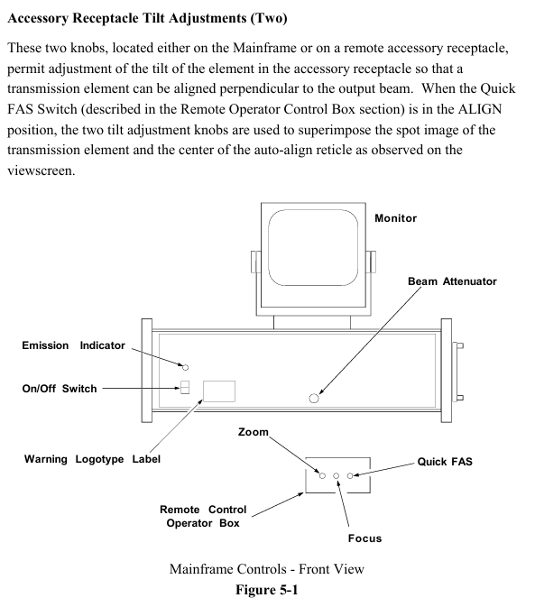
Familiarity with controls: Clearly define the functions of each button on the host and remote control box (such as the power switch, beam attenuation knob, and accessory socket tilt adjustment knob on the host; the fast stripe acquisition switch and zoom/focus adjustment switch on the remote box).
(2) Core operational steps
Boot startup
Confirm that the front beam attenuation knob of the host is pushed in, turn on the power switch, and the laser should start within 30 seconds. If it does not start, refer to the troubleshooting section of Service Manual SP-0038; There is a slow melting fuse on the back of the host (see Chapter 6 "Fuse Specifications" for the model).
Remote control box operation (see Figure 5-4)
Quick FAS switch: Center off, left dial "ALIGN" (alignment mode, hold for about 2 seconds, monitor displays aligned spot and automatic alignment crosshair), right dial "VIEW" (observation mode, hold for about 2 seconds, display interference pattern).
Zoom adjustment: With the center closed, it can achieve 6x continuous magnification (corresponding to aperture diameter for planar testing and f-number for spherical/cylindrical testing).
Focus adjustment: Center off, operate at 6x (or close to 6x) zoom, hold down the left and right keys, observe the edges of the test piece or small objects inserted into the beam (such as pen tips) until the outline is clearest (the stripes are not bent at the edges and are sharply truncated), do not directly focus on the stripes (their width is determined by the illumination intensity and needs to be adjusted by the monitor brightness/contrast).
Installation and alignment of transmission components
Universal installation: For transmissive components (flat or spherical), hold the metal edge in hand (do not touch the glass), loosen the spring clip screw of the accessory socket, insert the short metal pin of the component into the socket slot, and then rotate clockwise until it clicks into place. Finally, tighten the spring clip screw.
Alignment of transmission plane: After turning on the remote box, dial "ALIGN" for about 2 seconds, and the monitor will display a crosshair and two light spots (the bright spots are reflected by the uncoated surface of the transmission plane). Adjust the two tilt knobs of the accessory socket to make the bright spots coincide with the center of the crosshair.
Transmission sphere alignment: Remote box dial "ALIGN" for about 2 seconds, the monitor displays a crosshair and a light spot (reflected by the transmission element surface), adjust the tilt knob to make the light spot coincide with the center of the crosshair; Place the test piece (or 4% reflectivity concave convex surface) at the focal point of the converging beam of the transmissive element, and move the test piece so that the curvature center coincides with the focal point of the transmissive sphere (the bright spot converges at the center of the crosshair and disappears); Switch the "VIEW" mode. If the bull's-eye pattern displayed by the monitor is offset, use the X/Y knob of the 3/5 axis bracket to center (do not move the tilt knob of the host), and then focus through the Z axis knob (push the movement direction of the observation ring on the back of the bracket: move the Z axis clockwise when moving toward the center, and counterclockwise when moving outward). Finally, adjust the X/Y knob at the socket end of the transmission element to control the number of stripes to 0-7 (the best observation effect).
Installation and alignment of aperture converter
Preliminary preparation: Remove the transmission component from the accessory socket of the host, place a flat reflector with two axis brackets (reference or transmission plane) in the laser light path (about 45.7cm away from the host), and align the reflector using the "transmission plane alignment" process (this alignment state needs to be maintained).
Converter installation: Remove the transmission element from the converter, insert its short metal pin into the socket slot of the host accessory, push it in and rotate it to fix it, tighten the locking screw, align the tilt knob of the host accessory socket with the converter, and remove the flat reflector.
Component alignment: Install the transmission component on the converter, use the two tilt knobs at the aperture end of the converter (do not touch the host socket knob), and follow the "Transmission Component Alignment" process; If a transmissive sphere is installed on the converter, additional alignment checks are required: the test piece is placed at the focal point of the converging beam. In "VIEW" mode, if the target center pattern is offset, use the converter socket knob to adjust it. If the aperture is not full of the screen (vignetting), adjust it through the Zygo 3/5-axis bracket X/Y, and optimize the focusing method according to the spherical plane alignment. The final number of stripes is controlled between 0-7.
Interference pattern evaluation and geometric distortion inspection
Interference pattern evaluation: It is necessary to quantify the deviation between the test fringes and the ideal fitting pattern (usually expressed as a fraction of the ideal fringe spacing). It is recommended to refer to the "Interference Pattern Interpretation and Evaluation Manual AB-0001". Zygo provides real-time interference pattern evaluation equipment, and information can be requested as needed.
Geometric distortion inspection: Preheat the equipment for 30 minutes (the roundness change of the image during the preheating period is normal and does not need to be adjusted), remove the accessory socket transmission element, place a reference plane with two axis brackets (4% or 90% reflectivity) 12 inches away from the host, and align it with Quick FAS; Insert vertically arranged parallel thin lines (or adjustable parallelograms provided in the user manual) into the beam near the reference plane, zoom to 6x and restore to 1x, observe the monitor line pattern (which can be photographed by a video printer), and if there is non ideal distortion (such as aspect ratio deviation), refer to Service Manual SP-0038 for correction, or contact Zygo service department; If there is a ZAPP/PC system, the host signal can be directly evaluated (its circular mask should display as a perfect circle, and the host CCTV needs to be adjusted to fill the aperture image with the mask).
(3) Operation precautions
Do not touch the glass surface of optical accessories with bare hands. If touched without professional cleaning experience, do not clean it yourself (soft coating only has a reflectivity of 90% and is easily damaged); When not in use, the optical accessories should be returned to the protective box.
When installing optical accessories, avoid excessive force that may cause strain or damage to the components; When clamping attachments, do not tighten the screws too tightly to prevent deformation of the reference surface.
The accessories are lightly clamped with nylon screws on the two axis bracket. If the bracket tilts backwards, the accessories may fall off, so the bracket should not be moved or tilted when clamping the accessories.
The host needs to be used along the axis defined by the automatic alignment system, and the alignment accuracy must be ensured in the alignment mode, otherwise there may be no stripe display in the observation mode; The intensity of the two interfering beams needs to be close to obtain the best stripe contrast.
The distance between the test piece and the host should be moderate, shortening the optical path length of the last reflector and reducing the cavity length to reduce wavefront distortion caused by unstable air paths.
- YOKOGAWA
- Reliance
- ADVANCED
- SEW
- ProSoft
- WATLOW
- Kongsberg
- FANUC
- VSD
- DCS
- PLC
- man-machine
- Covid-19
- Energy and Gender
- Energy Access
- Renewable Integration
- Energy Subsidies
- Energy and Water
- Net zero emission
- Energy Security
- Critical Minerals
- A-B
- petroleum
- Mine scale
- Sewage treatment
- cement
- architecture
- Industrial information
- New energy
- Automobile market
- electricity
- Construction site
- HIMA
- ABB
- Rockwell
- Schneider Modicon
- Siemens
- xYCOM
- Yaskawa
- Woodward
- BOSCH Rexroth
- MOOG
- General Electric
- American NI
- Rolls-Royce
- CTI
- Honeywell
- EMERSON
- MAN
- GE
- TRICONEX
- Control Wave
- ALSTOM
- AMAT
- STUDER
- KONGSBERG
- MOTOROLA
- DANAHER MOTION
- Bentley
- Galil
- EATON
- MOLEX
- Triconex
- DEIF
- B&W
- ZYGO
- Aerotech
- DANFOSS
- KOLLMORGEN
- Beijer
- Endress+Hauser
- schneider
- Foxboro
- KB
- REXROTH
- YAMAHA
- Johnson
- Westinghouse
- WAGO
- TOSHIBA
- TEKTRONIX
- BENDER
- BMCM
- SMC
- HITACHI
- HIRSCHMANN
- XP POWER
- Baldor
- Meggitt
- SHINKAWA
- Other Brands
- UniOP
- KUKA
- IBA
- Beckhoff
- ADLINK
-
Beckhoff CX1100-0910 - Power Supply Module
-
Beckhoff C5210-0010 - Communication Module C5210
-
BECKHOFF KL1352 - Bus Terminal SET OF 2 FREE FAST SHIP
-
Beckhoff EL3058 - 8 x analog input single ended 4...20mA 85惟 shunt 12bit
-
Beckoff CX1100-0920 - UPS Module 24VDC (US SELLER) * *
-
BECKHOFF C6920-0000 - C69200000 PLC Moudule
-
Beckhoff CX5120-0115 - CPU controller module CX5120-0115
-
Unknown 15F5C1E-Y50A - Of Frequency Converters
-
Beckhoff AX5118-0000-0200 - Servo Drive HTP0
-
BECKHOFF AX5106-0000-0200 - Servo Drive
-
Beckhoff CX5240-0175 - Module (free) #U2327D YG
-
Beckhoff CP6607-0001-0000 - Compact PC Panel Economy Installation Operator 5,7 "
-
Beckhoff EP3744-0041 - 2022 EP37440041 Module
-
Beckhoff CP6209-0001-0020 - 6.5" PC Touch Screen Control Panel 24VDC
-
Beckhoff CX9020-0111 - /U900 +8x+2xEL3121+1x EL9410+3xEL1008+1x EL2008 Set
-
Beckhoff C6525-1030-0050 - Industrial PC
-
Beckoff CX1100-0920 - UPS Module 24VDC (US SELLER)
-
Beckhoff CX5010-0120 - CX5010 Processor Intel Atom Z510 B24
-
Siemens 6FC5203-0AF04-1BA1 - Operation Panel
-
Beckhoff CX5230-0175 - / 000029724 Embedded PC / Industrial PC on Rail
-
Beckhoff CP3916-0000 - industrielles Anzeige- und Bedienterminal
-
BECKHOFF CX1500-M310 - CX1000-N000 CX1000-0011 CX1000-C00L CX1100-0002 PLC Module
-
Beckhoff EL1872 - 16-channel digital input terminal
-
BECKHOFF EP2318-0001 - module
-
Beckhoff CX9020-0110 - Basic CPU Module
-
Beckhoff EL2564 - EtherCAT Terminal, 4-channel LED output, 5鈥?8VDC, 4A, RGBW
-
Beckhoff CX5130-0155 - /000105637 Automation Embedded PC
-
B&R 400 - Power Control Panel Rev D0 24 VDC
-
Beckhoff CX2020-0155 - module
-
Beckhoff CX9020-0115 - PLC Module
-
BECKHOFF EL6695 - PLC EL 6695
-
BECKHOFF EL7047 - PLC Modules
-
Beckhoff CX1000-0012 - Control HW 2.2 + CX1500-M310 + CX1000-C00L + CX1100-0002+
-
Beckhoff C6920-1039-0030 - control cabinet industrial PC CPU Celeron 1.90 GHz, 2 cores
-
BECKHOFF CX1100-0910 - PLC Module#
-
Beckhoff IL2301-B318-0000 - Coupler Box 4 Channel Digital Input |
-
Beckhoff CX7080 - Module
-
Beckhoff C6930-0060 - Industrial PC
-
Beckhoff CP7902-1060-0000 - Touchscreen 15 " CP7902
-
beckhoff CX9020-0111 - Controller module or UPS
-
Beckhoff CX8091 - PLC Module CX8091
-
Beckhoff C6640-1008-0030 - Control Cabinet Industrial PC
-
BECKHOFF CX1100-0920 - module
-
Beckhoff C9900-M921 - see pictures
-
BECKHOFF CP6829-0001-0000 - Touch Panel
-
BECKHOFF C6930-0060 - Industrial Computer
-
BECKHOFF CX8050 - PLC module
-
Beckhoff CP6202-0021-0020 - Touch Screen #
-
BECKHOFF AM3031-0C20-0000 - SERVO MOTOR
-
Unknown BCH1302N11A1C - Servo motor
-
Beckhoff EL2502 - 2-channel pulse width output terminal
-
Beckhoff EL6731 - Profibus Master / *Rev: 0025
-
Beckhoff CP3918-0010 - Control Panel
-
BECKHOFF CP2915-0010 - [24 MONTH WARRANTY] Control Panel
-
Beckhoff AX5203-0000-0202 - Servo Drive
-
Schneider TSXDSY64T2K - PLC OUTPUT MODULE
-
Beckhoff EP4174-0002 - Module-
-
Beckhoff IL2302-B318-0000 - Profibus Box
-
Beckhoff CP6709-0001-0000 - Touchpanel
-
BECKHOFF CX2030-0123 - Controller
-
Beckhoff CX9020-0111 - Processor Module
-
Beckhoff CX1020-0000 - CX Basic CPU Module
-
Beckhoff AX2003-AS - Servo Drive HTP0
-
Beckhoff C6240-1052-0040 - 4-086-06-3073 Industrial Computer CB1052-0003
-
Beckhoff EL1918 - 8 xTwinSAFE Input
-
Beckhoff AM8072-0R20-0000 - Servomotor
-
BECKHOFF AM8021-1B21-0000 - servo motor #T882 YS
-
Beckhoff EL6224 - 4 X Terminal IO-LINK
-
Beckhoff CX5140-0135 - embedded PC with Intel Atom processor 4 GB HW 3.6
-
Beckhoff CP7201-1000-0000 - Panel PC #
-
Beckhoff CX5130-0121 - Embedded-PC 4GB CPU Module HW 2.5 Industrial PC
-
Beckhoff AM8022-0D41-1002 - Servomotor
-
BECKHOFF CX2030-0130 - Module
-
BECKHOFF EL1872 - 16-channel digital input terminal
-
Unknown GXMMW.A203P33 - 1pc encoder
-
Beckhoff EL6631-0000 - EtherCAT Terminal 2-Port EL 6631
-
BECKHOFF C6925-0030 - Industrial Computer
-
Beckhoff CX8190 - A Module
-
BECKHOFF CX2040-0135 - CX2040-0135/000000927 CPU BASE MODULE i7 2715QE 2.1GHz --
-
BECKHOFF KL6023-0000 - Wireless adapter
-
Saia Burgess PCD7.F700 - PCD7F700 Communication Module
-
Beckhoff CX5130-0112 - CPU Module
-
BECKHOFF CX1020-N010 - CX1020-N000 CX1020-0111 CX1100-0004 EL2008 EL3064 EL4004
-
Beckhoff EP1819-0021 - A Module
-
Beckhoff CX2030-0120 - / 4gb with CX2100 0004
-
B&R X20-XC-0292 - Automation Powerlink Ethernet Bus Controller Module
-
Beckhoff BK3110 - One PLC Module
-
BECKHOFF KL3222 - PLC Module
-
BECKHOFF CX1500-M310 - CX1000-N000 CX1000-0011 CX1000-C00L CX1100-0002 PLC MODULE
-
Beckhoff CP3918-0010 - Control Panel
-
Beckhoff CX2030-0100-1002 - /4GB + CX2100 + CX2550 + CX2500-0060 + SSD
-
Beckhoff EP1816-0008 - PLC Module
-
Beckhoff CX5130-0112 - Module
-
Beckhoff Cx1500-m750 - CPU Hw: 1.4
-
BECKHOFF AX5112-0000-0200 - AX511200000200 Servo Driver
-
Beckhoff EL3751 - EtherCAT Terminal 1 Channel Analog Input Multifunction 24 Bit
-
Beckhoff CX1100-0002 - Power Supply Module
-
Beckhoff CP3916-1016-0010 - Control Panel
-
BECKHOFF CX9001-1101 - #NAME?
-
Beckhoff EP3174-0002 - EtherCAT Box Module
-
Beckhoff C6030-0070 - servo drive
-
Beckhoff CX2020-0120 - /4GB CPU, CX2100-0904, 3x EL6900, EL1904, 16GB Memory
-
BECKHOFF C6110 - BOX-PC 113608
-
BECKHOFF EK1914 - module #P
-
Beckhoff C6140 - Ipox IP-4GVI63 + CH7009A_DVI_TV + SIEMENS A5E00369843 + WD800AAJB
-
Beckhoff CX5020-0111 - controller Good quality
-
BECKHOFF C6015-0010 - / 6559380 ULTRA-COMPACT INDUSTRIAL PC ()
-
Beckhoff AX5203-0000-0200 - PLC module
-
Beckhoff EL2872 - 16-channel digital output terminal
-
BECKHOFF C3640-0000 - Panel Industrial PC 100/240VAC 128MB E0122L
-
Beckhoff CX8031 - Module
-
Beckhoff CX5020-0120-1002 - PLC module#
-
Beckhoff C6140 - M845B + SIEMENS A5E00369843 + C9900_A159_1 + AUTOMATA CAN PCI 1N
-
BECKHOFF AX5112-0000-0200 - Servo Drive*ie
-
B&R ECPA42-01 - Analog Output Module 4-Channel, +/- 10V Output Signal, 20mA Max
-
Beckhoff EL6631-0010 - PLC Module
-
BECKHOFF C6930-0070 - CONTROL CABINET INDUSTRIAL PC
-
BECKHOFF AX5112-0000-0200 - AX511200000200 Servo Driver
-
BECKHOFF EK9000 - Programmable Logic Controller Module EK9000 EK9000
-
BECKHOFF C6920-1028-0000 - Industrial computer
-
Beckhoff CX2030-0120 - controller Module
-
Beckhoff BX8000-0000 - Bus Terminal Controller HW 4.4
-
B&R 3NC154.60-2 - Positioning Module#
-
BECKHOFF CX1020-0122 - PLC module
-
Beckhoff AM3032-0D40-0000 - Servo Motor
-
BECKHOFF CX5020-0111 - CPU Module CX5020-0111
-
Beckhoff CB1051 - G5 Motherboard
-
BECKHOFF KL2641 - 1-channel relay output terminal

K-JIANG

Add: Jimei North Road, Jimei District, Xiamen, Fujian, China
Tell:+86-15305925923