
K-WANG


Woodward easyYgen LS-6XT series circuit breaker control unit
Woodward easyYgen LS-6XT series circuit breaker control unit
Basic Information
Product model easyYgen LS-6XT series (representative model LS-612XT-P1/P2)
Core positioning circuit breaker control, dual system synchronous monitoring, fault alarm, logic expansion
Adaptation target engine generator set (GCB/MCB/GGB control)
Certification qualifications UL/cUL, CE, Lloyd's (ENV1/ENV2), ABS classification certification
System hardware and interface configuration
(1) Core interface parameters
Interface type specification details
The input voltage range of the power supply is 8-40Vdc. It is recommended to connect a 6A slow melting fuse in series, with a power consumption of about 6W
Voltage measurement (dual system) supports 3Ph4W/3Ph3W/1Ph3W/1Ph2W wiring; Measurement range 120/480/690Vac (PT secondary side)
Current measurement (dual system) supports L1/L2/L3 three-phase or single phase to ground measurement; CT input 1A/5A optional, system A occupies 6 terminals, system B occupies 2 terminals
Discrete Input (DI) 12 channel optical isolation, input voltage 8-40Vdc, supports NO/NC configuration; Can be extended to 32 channels (P2 model) through IKD module
Discrete Output (DO) 12 way relay, passive contacts, universal load 2A@250Vac /24Vdc; Can be extended to 32 channels (P2 model) through IKD module
Analog input (AI) 3 channels, supporting 0-2000 Ω (resistance type), 0/4-20mA (current type), 0-1V (voltage type), supporting Pt100/Pt1000/VDO sensors
Analog output (AO) 2 channels, supporting ± 20mA, ± 10V, PWM output, galvanic isolation, configurable filtering time constant
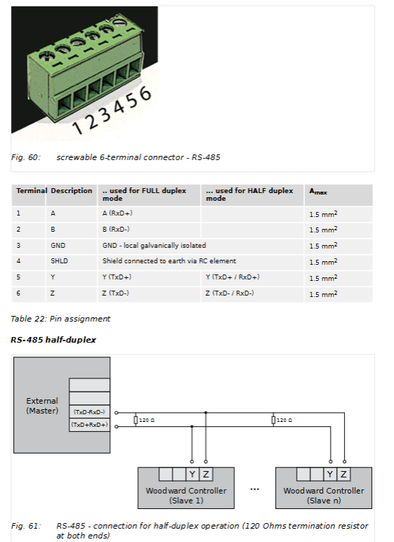
Communication interface RS-485: supports half/full duplex, with maximum transmission distance dependent on baud rate; USB 2.0: Service port, ToolKit connection; CAN Bus: Supports CANopen, up to 2500m (20kBaud); Ethernet: 3 RJ-45 ports, supporting 10/100Base-T, maximum transmission of 100m
(2) Structure and environmental specifications
Category specific parameters
The shell structure is made of metal material, with dimensions of 227 (width) x 250 (height) x 50 (depth) mm; the panel openings must comply with the drill plan
Protection level IP66 (screw installation), IP54 (fixture installation), IP20 (back)
Environmental tolerance working temperature -20 ° C~70 ° C, storage temperature -30 ° C~80 ° C; humidity 95%, no condensation (85% when ≤ 40 ° C)
Anti interference performance vibration: 5-100Hz sine sweep frequency (4G), 10-500Hz random vibration (1.04Grms); Shock: 40G sawtooth wave pulse (11ms)
Core functions and operations
(1) Core control function
Circuit breaker control: supports the closing/opening of CBA (main circuit breaker) and CBB (backup circuit breaker), can be configured with pulse (0.1-9.9s) or continuous output mode, supports automatic unlocking (Pre open pulse) function
Synchronous grid connection control: Monitor the voltage difference (0.50-20.00%), frequency difference (± 0.49Hz), and phase difference (± 60 °) of the dual systems, trigger grid connection after meeting the conditions, and support phase compensation (-180 °~180 °)
Dead bus closure: supports both A/B dual systems to be dead, one dead and one active scenario closure, detection threshold 0-30% rated voltage, delay 0-20s, supports multi device negotiation mechanism
Load transfer: Supports four modes: Open Transition, Closed Transition, Interchange, and Parallel
Fault decoupling: Monitor thresholds such as over/under frequency, over/under voltage, phase offset, df/dt, etc., and automatically disconnect the designated circuit breaker (CBA/BBB or both) upon triggering
(2) Programming and configuration methods
Configuration Method Operation Path Core Function
Local operation front-end panel (LCD+buttons) parameter viewing, mode switching, manual control of circuit breakers, alarm confirmation
Remote Panel RP-3000XT (Ethernet) fully functional visual operation, supporting Full/Annunciator/Off modes
PC configuration ToolKit software (Windows 7/8.1/10) includes full parameter configuration, logic programming, analog processing, data trend monitoring, and log export
LogicsManager supports logical combinations such as AND/OR/NAND, and can customize discrete I/O associations and alarm triggering conditions
Analog Manager supports 8 types of sensor curves, 2 custom tables (9-point calibration), and unit conversion (° C → ° F, bar → psi) for analog processing
(3) Alarm and Log
Alarm level: Level 6 (A-F), Level A/B for warning (no trip), Level C-F for shutdown (disconnect circuit breaker)
Event log: records 300 system events (including timestamps), supports FIFO storage, and can be manually cleared
Alarm monitoring: covering 20+types of alarms such as voltage/frequency exceeding limits, phase rotation mismatch, I/O faults, communication abnormalities, etc

Key configuration parameters
(1) Permission and password grading
Permission level, access method, core permissions
CL0 (user level) no password, only view data, confirm alarms
CL1 (basic level) password 0001 modification of non critical parameters (such as language, unit)
CL3 (debugging level) password 0003 full parameter configuration, logic programming, factory reset
CL5 (Super Debugging Level) Password 0500 Firmware Update, Advanced Parameter Configuration
Temporary permission algorithm generates password for temporary access to corresponding level, automatically exits upon timeout
(2) Example of Core Function Configuration Parameters
Parameter Category Key Parameters Default Value Configuration Range
Synchronous Control Voltage Difference Threshold (CBA) 5.00% 0.50-20.00%
Frequency difference threshold (CBA) ± 0.18Hz -0.49-0.49Hz
Phase difference threshold (CBA) ± 7.0 ° -60.0-60.0 °
Dead bus control detection threshold 10% 0-30%
Closing delay 5.0s 0.0-20.0s
Communication configuration CANopen baud rate 125kBaud 20-1000kBaud
Ethernet IP Mode Static/Dynamic (DHCP)
Load Transfer Time (CBA) ↔ CBB) 1.00s 0.50-99.99s
Key issue
Question 1: How is the dual circuit breaker (CBA/BBB) control function of LS-6XT implemented, and what are the core configuration differences?
Answer: The dual circuit breaker control is achieved through the "CBA/BBB mode", and the core is the independent control and linkage logic of the two circuit breakers: ① Hardware configuration: CBA corresponds to the main circuit breaker, CBB corresponds to the backup/load circuit breaker, both support closing/opening pulse/continuous control, and can be configured with automatic unlocking (Pre open) function; ② Core differences: CBA focuses on main circuit grid connection, dead bus closure, and system A decoupling, while CBB focuses on backup circuit switching and system B associated control, with CBA having higher closure priority than CBB; ③ Linkage logic: supports load transfer (four modes), synchronous grid connection linkage (CBB synchronization after CBA closure), and selective disconnection in case of failure (such as CBA disconnection in case of system A failure and CBB disconnection in case of system B failure); ④ Configuration points: It is necessary to switch between "CBA"/"CBA/BBB" modes through parameter 9018 (Breaker mode), and configure the synchronization threshold, dead bus condition, and linkage delay of both modes separately.
Question 2: How to configure and use the extended I/O (IKD module) of LS-6XT, and what extension scenarios are supported?
Answer: The IKD module is an external I/O expansion solution, with the following core configurations and scenarios: ① Supported module types: IKD1 (8DI+8DO), IKD-IN-16 (16DI), IKD-OUT-16 (16DO), P1 model supports 2 IKDs (16DI+16DO), P2 model supports 4 IKDs (32DI+32DO); ② Connection method: Connected through CAN1 bus, CAN baud rate and module address need to be configured, shielded cable exposed length ≤ 25mm; ③ Configuration path: "Configure Input/Output → External Discrete Input/Output" in ToolKit, can set DI alarm level, delay time, and logical association of DO; ④ Extended scenarios: Suitable for complex systems that require more discrete signal acquisition (such as multi-sensor alarms) or output control (such as multi actuator linkage), such as multi loop state monitoring in ship power systems and multi device linkage control in industrial units.
Question 3: What is the core logic and safety mechanism of the synchronous grid connection and dead bus closure function of LS-6XT?
Answer: Both are the core functions of circuit breaker closure, and the logic and safety mechanism are as follows: ① Synchronous grid connection logic: Real time monitoring of dual system voltage/frequency/phase, meeting preset thresholds (voltage difference ≤ 20%, frequency difference ≤± 0.49Hz, phase difference ≤± 60 °) and continuously setting time (default 3s), triggering closure; Supports two synchronization modes: "slip frequency" and "phase matching", which can offset transformer phase offset through phase compensation; ② Dead bus closure logic: detects that the system voltage is below the threshold (0-30% rated voltage) and has a continuous delay time (0-20s), triggering after meeting the "no other device closure request" (multi device negotiation), supporting three scenarios: A dead B dead, A dead B live, A live B dead; ③ Security mechanism: Verify phase sequence consistency (CW/CCW) before synchronous grid connection, and block closure if inconsistent; The closure of the dead bus requires the "Enable close" logic to be enabled through LogicsManager, and there should be no C/F level alarms; In multi device scenarios, using "device number priority" to avoid simultaneous closure and automatically releasing permissions after closure failure ensures system security.
- YOKOGAWA
- Reliance
- ADVANCED
- SEW
- ProSoft
- WATLOW
- Kongsberg
- FANUC
- VSD
- DCS
- PLC
- man-machine
- Covid-19
- Energy and Gender
- Energy Access
- Renewable Integration
- Energy Subsidies
- Energy and Water
- Net zero emission
- Energy Security
- Critical Minerals
- A-B
- petroleum
- Mine scale
- Sewage treatment
- cement
- architecture
- Industrial information
- New energy
- Automobile market
- electricity
- Construction site
- HIMA
- ABB
- Rockwell
- Schneider Modicon
- Siemens
- xYCOM
- Yaskawa
- Woodward
- BOSCH Rexroth
- MOOG
- General Electric
- American NI
- Rolls-Royce
- CTI
- Honeywell
- EMERSON
- MAN
- GE
- TRICONEX
- Control Wave
- ALSTOM
- AMAT
- STUDER
- KONGSBERG
- MOTOROLA
- DANAHER MOTION
- Bentley
- Galil
- EATON
- MOLEX
- Triconex
- DEIF
- B&W
- ZYGO
- Aerotech
- DANFOSS
- KOLLMORGEN
- Beijer
- Endress+Hauser
- schneider
- Foxboro
- KB
- REXROTH
- YAMAHA
- Johnson
- Westinghouse
- WAGO
- TOSHIBA
- TEKTRONIX
- BENDER
- BMCM
- SMC
- HITACHI
- HIRSCHMANN
- XP POWER
- Baldor
- Meggitt
- SHINKAWA
- Other Brands
- UniOP
- KUKA
- IBA
- Beckhoff
- ADLINK
-
Beckhoff CX1100-0910 - Power Supply Module
-
Beckhoff C5210-0010 - Communication Module C5210
-
BECKHOFF KL1352 - Bus Terminal SET OF 2 FREE FAST SHIP
-
Beckhoff EL3058 - 8 x analog input single ended 4...20mA 85惟 shunt 12bit
-
Beckoff CX1100-0920 - UPS Module 24VDC (US SELLER) * *
-
BECKHOFF C6920-0000 - C69200000 PLC Moudule
-
Beckhoff CX5120-0115 - CPU controller module CX5120-0115
-
Unknown 15F5C1E-Y50A - Of Frequency Converters
-
Beckhoff AX5118-0000-0200 - Servo Drive HTP0
-
BECKHOFF AX5106-0000-0200 - Servo Drive
-
Beckhoff CX5240-0175 - Module (free) #U2327D YG
-
Beckhoff CP6607-0001-0000 - Compact PC Panel Economy Installation Operator 5,7 "
-
Beckhoff EP3744-0041 - 2022 EP37440041 Module
-
Beckhoff CP6209-0001-0020 - 6.5" PC Touch Screen Control Panel 24VDC
-
Beckhoff CX9020-0111 - /U900 +8x+2xEL3121+1x EL9410+3xEL1008+1x EL2008 Set
-
Beckhoff C6525-1030-0050 - Industrial PC
-
Beckoff CX1100-0920 - UPS Module 24VDC (US SELLER)
-
Beckhoff CX5010-0120 - CX5010 Processor Intel Atom Z510 B24
-
Siemens 6FC5203-0AF04-1BA1 - Operation Panel
-
Beckhoff CX5230-0175 - / 000029724 Embedded PC / Industrial PC on Rail
-
Beckhoff CP3916-0000 - industrielles Anzeige- und Bedienterminal
-
BECKHOFF CX1500-M310 - CX1000-N000 CX1000-0011 CX1000-C00L CX1100-0002 PLC Module
-
Beckhoff EL1872 - 16-channel digital input terminal
-
BECKHOFF EP2318-0001 - module
-
Beckhoff CX9020-0110 - Basic CPU Module
-
Beckhoff EL2564 - EtherCAT Terminal, 4-channel LED output, 5鈥?8VDC, 4A, RGBW
-
Beckhoff CX5130-0155 - /000105637 Automation Embedded PC
-
B&R 400 - Power Control Panel Rev D0 24 VDC
-
Beckhoff CX2020-0155 - module
-
Beckhoff CX9020-0115 - PLC Module
-
BECKHOFF EL6695 - PLC EL 6695
-
BECKHOFF EL7047 - PLC Modules
-
Beckhoff CX1000-0012 - Control HW 2.2 + CX1500-M310 + CX1000-C00L + CX1100-0002+
-
Beckhoff C6920-1039-0030 - control cabinet industrial PC CPU Celeron 1.90 GHz, 2 cores
-
BECKHOFF CX1100-0910 - PLC Module#
-
Beckhoff IL2301-B318-0000 - Coupler Box 4 Channel Digital Input |
-
Beckhoff CX7080 - Module
-
Beckhoff C6930-0060 - Industrial PC
-
Beckhoff CP7902-1060-0000 - Touchscreen 15 " CP7902
-
beckhoff CX9020-0111 - Controller module or UPS
-
Beckhoff CX8091 - PLC Module CX8091
-
Beckhoff C6640-1008-0030 - Control Cabinet Industrial PC
-
BECKHOFF CX1100-0920 - module
-
Beckhoff C9900-M921 - see pictures
-
BECKHOFF CP6829-0001-0000 - Touch Panel
-
BECKHOFF C6930-0060 - Industrial Computer
-
BECKHOFF CX8050 - PLC module
-
Beckhoff CP6202-0021-0020 - Touch Screen #
-
BECKHOFF AM3031-0C20-0000 - SERVO MOTOR
-
Unknown BCH1302N11A1C - Servo motor
-
Beckhoff EL2502 - 2-channel pulse width output terminal
-
Beckhoff EL6731 - Profibus Master / *Rev: 0025
-
Beckhoff CP3918-0010 - Control Panel
-
BECKHOFF CP2915-0010 - [24 MONTH WARRANTY] Control Panel
-
Beckhoff AX5203-0000-0202 - Servo Drive
-
Schneider TSXDSY64T2K - PLC OUTPUT MODULE
-
Beckhoff EP4174-0002 - Module-
-
Beckhoff IL2302-B318-0000 - Profibus Box
-
Beckhoff CP6709-0001-0000 - Touchpanel
-
BECKHOFF CX2030-0123 - Controller
-
Beckhoff CX9020-0111 - Processor Module
-
Beckhoff CX1020-0000 - CX Basic CPU Module
-
Beckhoff AX2003-AS - Servo Drive HTP0
-
Beckhoff C6240-1052-0040 - 4-086-06-3073 Industrial Computer CB1052-0003
-
Beckhoff EL1918 - 8 xTwinSAFE Input
-
Beckhoff AM8072-0R20-0000 - Servomotor
-
BECKHOFF AM8021-1B21-0000 - servo motor #T882 YS
-
Beckhoff EL6224 - 4 X Terminal IO-LINK
-
Beckhoff CX5140-0135 - embedded PC with Intel Atom processor 4 GB HW 3.6
-
Beckhoff CP7201-1000-0000 - Panel PC #
-
Beckhoff CX5130-0121 - Embedded-PC 4GB CPU Module HW 2.5 Industrial PC
-
Beckhoff AM8022-0D41-1002 - Servomotor
-
BECKHOFF CX2030-0130 - Module
-
BECKHOFF EL1872 - 16-channel digital input terminal
-
Unknown GXMMW.A203P33 - 1pc encoder
-
Beckhoff EL6631-0000 - EtherCAT Terminal 2-Port EL 6631
-
BECKHOFF C6925-0030 - Industrial Computer
-
Beckhoff CX8190 - A Module
-
BECKHOFF CX2040-0135 - CX2040-0135/000000927 CPU BASE MODULE i7 2715QE 2.1GHz --
-
BECKHOFF KL6023-0000 - Wireless adapter
-
Saia Burgess PCD7.F700 - PCD7F700 Communication Module
-
Beckhoff CX5130-0112 - CPU Module
-
BECKHOFF CX1020-N010 - CX1020-N000 CX1020-0111 CX1100-0004 EL2008 EL3064 EL4004
-
Beckhoff EP1819-0021 - A Module
-
Beckhoff CX2030-0120 - / 4gb with CX2100 0004
-
B&R X20-XC-0292 - Automation Powerlink Ethernet Bus Controller Module
-
Beckhoff BK3110 - One PLC Module
-
BECKHOFF KL3222 - PLC Module
-
BECKHOFF CX1500-M310 - CX1000-N000 CX1000-0011 CX1000-C00L CX1100-0002 PLC MODULE
-
Beckhoff CP3918-0010 - Control Panel
-
Beckhoff CX2030-0100-1002 - /4GB + CX2100 + CX2550 + CX2500-0060 + SSD
-
Beckhoff EP1816-0008 - PLC Module
-
Beckhoff CX5130-0112 - Module
-
Beckhoff Cx1500-m750 - CPU Hw: 1.4
-
BECKHOFF AX5112-0000-0200 - AX511200000200 Servo Driver
-
Beckhoff EL3751 - EtherCAT Terminal 1 Channel Analog Input Multifunction 24 Bit
-
Beckhoff CX1100-0002 - Power Supply Module
-
Beckhoff CP3916-1016-0010 - Control Panel
-
BECKHOFF CX9001-1101 - #NAME?
-
Beckhoff EP3174-0002 - EtherCAT Box Module
-
Beckhoff C6030-0070 - servo drive
-
Beckhoff CX2020-0120 - /4GB CPU, CX2100-0904, 3x EL6900, EL1904, 16GB Memory
-
BECKHOFF C6110 - BOX-PC 113608
-
BECKHOFF EK1914 - module #P
-
Beckhoff C6140 - Ipox IP-4GVI63 + CH7009A_DVI_TV + SIEMENS A5E00369843 + WD800AAJB
-
Beckhoff CX5020-0111 - controller Good quality
-
BECKHOFF C6015-0010 - / 6559380 ULTRA-COMPACT INDUSTRIAL PC ()
-
Beckhoff AX5203-0000-0200 - PLC module
-
Beckhoff EL2872 - 16-channel digital output terminal
-
BECKHOFF C3640-0000 - Panel Industrial PC 100/240VAC 128MB E0122L
-
Beckhoff CX8031 - Module
-
Beckhoff CX5020-0120-1002 - PLC module#
-
Beckhoff C6140 - M845B + SIEMENS A5E00369843 + C9900_A159_1 + AUTOMATA CAN PCI 1N
-
BECKHOFF AX5112-0000-0200 - Servo Drive*ie
-
B&R ECPA42-01 - Analog Output Module 4-Channel, +/- 10V Output Signal, 20mA Max
-
Beckhoff EL6631-0010 - PLC Module
-
BECKHOFF C6930-0070 - CONTROL CABINET INDUSTRIAL PC
-
BECKHOFF AX5112-0000-0200 - AX511200000200 Servo Driver
-
BECKHOFF EK9000 - Programmable Logic Controller Module EK9000 EK9000
-
BECKHOFF C6920-1028-0000 - Industrial computer
-
Beckhoff CX2030-0120 - controller Module
-
Beckhoff BX8000-0000 - Bus Terminal Controller HW 4.4
-
B&R 3NC154.60-2 - Positioning Module#
-
BECKHOFF CX1020-0122 - PLC module
-
Beckhoff AM3032-0D40-0000 - Servo Motor
-
BECKHOFF CX5020-0111 - CPU Module CX5020-0111
-
Beckhoff CB1051 - G5 Motherboard
-
BECKHOFF KL2641 - 1-channel relay output terminal

K-JIANG

Add: Jimei North Road, Jimei District, Xiamen, Fujian, China
Tell:+86-15305925923