
K-WANG


YASKAWA 1000 series frequency converter
YASKAWA 1000 series frequency converter
Core Overview
This document is the Spanish technical manual (manual number TOSP C710606 22B) for the Yaskawa V1000 series vector controlled compact frequency converter (model CIMR-VU), covering 200V single/three-phase (0.1-18.5kW) and 400V three-phase (0.2-18.5kW) models. The core provides guidance around the entire life cycle of the equipment, including receiving inspection, mechanical/electrical installation, programming start-up, troubleshooting, regular maintenance, peripheral equipment adaptation and other key contents. It emphasizes safe operation norms and precise parameter configuration, supports the control of ordinary induction motors and permanent magnet synchronous motors (PM), and provides comprehensive technical support for installation, commissioning, daily operation and maintenance, and fault resolution in industrial scenarios.
Detailed analysis of core chapters
Basic Information and Security Principles of Documents
Basic Information
Product positioning: Vector controlled compact frequency converter, suitable for 7 typical industrial applications such as pumps, conveyors, fans, compressors, cranes, etc.
Voltage and power range: 200V single-phase (0.1-5.5kW), 200V three-phase (0.1-18.5kW), 400V three-phase (0.2-18.5kW).
Document purpose: To guide users in correctly installing, operating, and maintaining equipment, and to clarify that users need to pass on the manual to the end user.
Copyright Notice: All rights reserved by Yaskawa Electric in 2008. Reproduction and dissemination are prohibited without written permission. Product information may change with upgrades, and we do not assume any responsibility for losses caused by misuse of information.
General Safety Principles
Security level definition: divided into four levels: "PELIGRO (fatal danger)", "ADVERTENCIA (serious danger)", "PRECAUCI Ó N (minor injury)", "AVISO (property damage)", clarifying the warning requirements for different risk scenarios.
Core safety regulations: After power failure, wait for ≥ 5 minutes for capacitor discharge (bus voltage<50Vdc); Prohibit live wiring or touching circuit boards; Only qualified personnel are allowed to operate; The equipment needs to be fixed on a non flammable material surface; Avoid using incompatible voltage power sources.
Special warning: When connecting the motor to the frequency converter, it is forbidden to plug or unplug it with power on; Prohibit conducting voltage withstand tests on frequency converters; Follow the electrostatic discharge (ESD) process; Single phase motors cannot be used in conjunction with this frequency converter.
Reception and Inspection
Core Inspection Process
Appearance and damage inspection: After receiving, confirm that the equipment is not damaged during transportation. If there is any damage, immediately contact the transportation party.
Model and nameplate verification: Confirm the model, input/output specifications, serial number and order consistency through the nameplate. The nameplate includes key information such as working mode (normal/heavy load), voltage level, output current, etc.
Model and protection type: The frequency converter provides two types of protection: IP20/open type (to be installed in a closed panel) and IP20/NEMA1 type (wall mounted), which need to be selected according to the installation scenario.
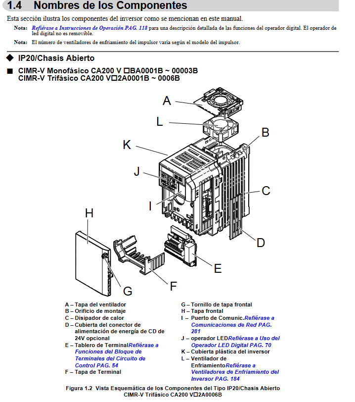
Component Identification
The key components include LED operators, heat sinks, terminal blocks, cooling fans, communication ports, etc. The layout of components with different protection types and power levels varies, and needs to be confirmed by referring to the manual illustrations.
Mechanical Installation
Installation environment requirements
Environmental conditions: Indoor installation, temperature range IP20 open type (-10~50 ℃), IP20/NEMA1 type (-10~40 ℃), humidity ≤ 95%, no condensation, altitude ≤ 1000m, no dust, oil pollution, strong vibration (10-20Hz ≤ 9.8m/s ², 20-55Hz ≤ 5.9m/s ²).
Taboo environment: Avoid direct sunlight, corrosive gases, radioactive substances, and installation near flammable materials.
Installation specifications
Installation direction: It must be installed vertically to ensure heat dissipation effect, and horizontal or inclined installation is prohibited.
Spacing requirements: The vertical spacing of a single device should be ≥ 100mm, and the horizontal spacing should be ≥ 30mm; when multiple devices are installed side by side, the adjacent spacing should be ≥ 2mm, and the rated power should be reduced and the parameter L8-35 adjusted.
Size and fixing: The external dimensions and installation holes of different models of frequency converters vary, and the appropriate installation method should be selected according to the manual table. The fixing torque should meet the requirements (such as 0.5-0.6N · m for M3 bolts).
Electrical Installation
Wiring Safety and Standards
Wiring prerequisite: Power off and wait for the capacitor to discharge completely, wear insulation protective equipment to avoid cable cross interference.
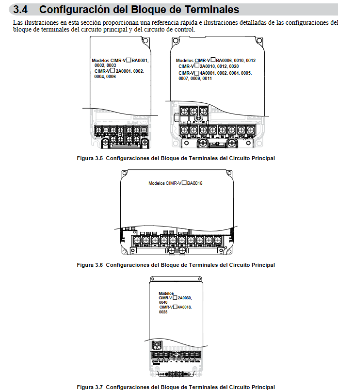
Main circuit wiring: Use 600V ethylene insulated cables, and connect the main circuit terminals (R/L1, S/L2, T/L3, U/T1, V/T2, W/T3, etc.) according to the diagram. The grounding requirements are 200V level ≤ 100 Ω and 400V level ≤ 10 Ω.
Control circuit wiring: Use shielded twisted pair cables to avoid parallel connection with the main circuit cables, and the shielding layer needs to be grounded; The control circuit terminals include digital input/output, analog input/output, communication terminals, etc., which need to be wired according to functional configuration.
Key Wiring Details
Braking resistor connection: can only be connected to B1/B2 terminals, and needs to be protected by a thermal relay to avoid overload and burnout.
Communication wiring: Supports MEMOBU/Modbus communication, requires the use of RS-485/422 cables, and the terminal resistance is controlled through DIP switch S2 (the end device needs to be turned on).
Cable specifications: Select the appropriate cable cross-sectional area based on the frequency converter model (such as 2mm ² recommended for the main circuit cable of the 200V single-phase 0.1kW model). After wiring, tighten the terminals with the required torque (such as 0.8-1.0N · m for M3.5 bolts).
Programming and Startup Operations
Use of LED Operators
Operator functions: including data display area, ESC key, RESET key, RUN key, up and down arrow keys, STOP key, ENTER key, LO/RE switch key, which can realize mode switching, parameter editing, operation monitoring, fault reset and other operations.
Display and indicator lights: RUN indicator light displays the running status, LO/RE indicator light displays the local/remote mode, ALM indicator light displays the fault status, and frequency, current, parameter and other information can be viewed through the digital display area.
Core Programming Settings
Control mode selection: Set through parameter A1-02, supporting V/f control (0), open-loop vector control (2), and open-loop vector control of permanent magnet synchronous motor (5).
Application preset parameters: Select 7 types of application presets (pumps, conveyors, etc.) through parameter A1-06, automatically configure the optimal parameters, and simplify debugging.
Basic parameter configuration: including acceleration/deceleration time (C1-01~C1-11), carrier frequency (C6-02, 2-15kHz optional), motor parameters (E2-01~E2-12, configurable through automatic adjustment function), frequency command source (b1-01), etc.
Start up process
Initialization settings: Select control mode and application presets based on the application scenario, and initialize parameters (A1-03).
Auto Ajuste: divided into rotary type (motor rotation, adapted to open-loop vector control) and stationary type (motor non rotation, adapted to V/f control), used for automatically configuring motor parameters to ensure control accuracy.
Trial operation: No load test (to confirm motor steering, acceleration/deceleration stability) → Load test (to verify operating status and parameter effectiveness) → Jogging operation (FJOG/RJOG function, 6Hz low-speed test).
Troubleshooting
Fault classification and warning
Fault types: including hardware faults such as overcurrent (oC), overvoltage (ov), overload (oL1/oL2), overheating (oH), operational errors such as communication errors (CE), parameter errors (oPE), and adjustment errors during the Auto Ajuste process.
Warning method: When a fault occurs, the LED operator displays a fault code and the ALM indicator light remains on; The ALM indicator light flashes when there is a minor malfunction or alarm.
Common troubleshooting solutions
Overvoltage (ov): Extend deceleration time (C1-02, etc.), install braking resistors, enable overvoltage suppression function (L3-11=1), check input voltage spikes.
Overcurrent (oC): Check motor insulation and wiring, reduce load, extend acceleration time, lower carrier frequency, confirm motor type matches control mode.
Overload (oL1): Reduce load, extend acceleration/deceleration time, check motor rated current configuration (E2-01), confirm motor cooling system is normal.
Parameter Error (oPE): Verify the parameter configuration logic (such as matching carrier frequency and cable length), restore default parameters, and reconfigure.
Fault reset method
Manual reset: Reset by pressing the RESET button on the operator.
Automatic reset: Configure parameter L5-01 to set the number of automatic retries.
Power off reset: Disconnect the power supply for ≥ 5 minutes and then power it back on (applicable to serious faults).
Regular Maintenance and Overhaul
Maintenance cycle and projects
Daily inspection: clean appearance, running sound, heat dissipation, terminal fastening status.
Regular inspection: Check cable aging, cooling fan operation status, capacitor and IGBT status every 6 months to 1 year (monitored through U4-05/U4-07).
Maintenance cycle: When the service life of the cooling fan expires (U4-04 ≥ 90%), it needs to be replaced in a timely manner; Replace capacitors and IGBTs when they reach the maintenance threshold.
Maintenance of key components
Cooling fan: Regularly clean the dust on the fan blades, replace them when damaged or aged, and reset the parameter o4-03=0 after replacement.
Terminals and cables: Check the tightness of the wiring to avoid looseness and overheating; Replace aging cables in a timely manner to ensure insulation performance.
Inverter replacement: During replacement, parameter configuration can be transferred through a detachable terminal block to reduce the workload of reprogramming.
Peripheral Devices and Options
Peripheral Device Adaptation
Protective equipment: Molded Case Circuit Breakers (MCCBs), Residual Current Circuit Breakers, Thermal Relays (OL), etc. must be installed to comply with local electrical regulations.
Filtering and reactors: Input filters, EMC filters, and AC/DC reactors can be installed to reduce electromagnetic interference and improve input current waveforms.
Communication Options
Supports MEMOBU/Modbus communication protocols and can be adapted to more bus protocols by extending the communication card. Wiring must follow communication specifications and configure corresponding parameters (such as baud rate and address).
Technical Specifications and Parameter List
Core specifications
Output characteristics: Voltage range 0- input voltage, frequency range 0-400Hz, overload capacity of normal working mode 120%/60s, overload mode 150%/60s.
Protection function: including multiple protections such as overcurrent, overvoltage, overload, overheating, phase loss, and ground fault.
Parameter List
Parameter grouping: divided into initialization parameters (A), application parameters (b), adjustment parameters (C), motor parameters (E), terminal function parameters (H), protection function parameters (L), monitoring parameters (U), etc., covering all configurable items such as control mode, operating parameters, protection thresholds, etc. Each parameter is labeled with default values, configuration ranges, and functional descriptions.
Key technical points
Motor adaptation
Supports ordinary induction motors and permanent magnet synchronous motors (PM). Permanent magnet synchronous motors require motor code (E5-01) and related parameters (E5-02~E5-24) to be configured, and speed search function (b3-01=1) to be enabled.
Motor parameter configuration: Accurate input of motor rated current, number of poles, rated power, and other information is required, or automatically obtained through the Auto Ajuste function to ensure control accuracy.
Differences in Control Modes
V/f control: Suitable for ordinary speed regulation scenarios (such as fans and pumps), with a simple structure and support for multi motor control.
Open loop vector control: suitable for high-precision speed regulation and high starting torque scenarios (such as conveyors and cranes), requiring Auto Ajuste to optimize parameters.
Permanent magnet synchronous motor control: efficient and energy-saving, suitable for scenarios with variable torque and high energy efficiency requirements, requiring dedicated parameter configuration.
Core taboos for safe operation
Prohibited items: live wiring/plugging of components, use of single-phase motors, covering of heat dissipation ports, modification of internal circuits of frequency converters, use of mismatched voltage power supplies.
Required items: reliable grounding, operation after power outage and discharge, operation by qualified personnel, tightening terminals according to specifications, regular maintenance of cooling system.
- YOKOGAWA
- Reliance
- ADVANCED
- SEW
- ProSoft
- WATLOW
- Kongsberg
- FANUC
- VSD
- DCS
- PLC
- man-machine
- Covid-19
- Energy and Gender
- Energy Access
- Renewable Integration
- Energy Subsidies
- Energy and Water
- Net zero emission
- Energy Security
- Critical Minerals
- A-B
- petroleum
- Mine scale
- Sewage treatment
- cement
- architecture
- Industrial information
- New energy
- Automobile market
- electricity
- Construction site
- HIMA
- ABB
- Rockwell
- Schneider Modicon
- Siemens
- xYCOM
- Yaskawa
- Woodward
- BOSCH Rexroth
- MOOG
- General Electric
- American NI
- Rolls-Royce
- CTI
- Honeywell
- EMERSON
- MAN
- GE
- TRICONEX
- Control Wave
- ALSTOM
- AMAT
- STUDER
- KONGSBERG
- MOTOROLA
- DANAHER MOTION
- Bentley
- Galil
- EATON
- MOLEX
- Triconex
- DEIF
- B&W
- ZYGO
- Aerotech
- DANFOSS
- KOLLMORGEN
- Beijer
- Endress+Hauser
- schneider
- Foxboro
- KB
- REXROTH
- YAMAHA
- Johnson
- Westinghouse
- WAGO
- TOSHIBA
- TEKTRONIX
- BENDER
- BMCM
- SMC
- HITACHI
- HIRSCHMANN
- XP POWER
- Baldor
- Meggitt
- SHINKAWA
- Other Brands
- UniOP
- KUKA
- IBA
- Beckhoff
- ADLINK
-
Beckhoff CX1100-0910 - Power Supply Module
-
Beckhoff C5210-0010 - Communication Module C5210
-
BECKHOFF KL1352 - Bus Terminal SET OF 2 FREE FAST SHIP
-
Beckhoff EL3058 - 8 x analog input single ended 4...20mA 85惟 shunt 12bit
-
Beckoff CX1100-0920 - UPS Module 24VDC (US SELLER) * *
-
BECKHOFF C6920-0000 - C69200000 PLC Moudule
-
Beckhoff CX5120-0115 - CPU controller module CX5120-0115
-
Unknown 15F5C1E-Y50A - Of Frequency Converters
-
Beckhoff AX5118-0000-0200 - Servo Drive HTP0
-
BECKHOFF AX5106-0000-0200 - Servo Drive
-
Beckhoff CX5240-0175 - Module (free) #U2327D YG
-
Beckhoff CP6607-0001-0000 - Compact PC Panel Economy Installation Operator 5,7 "
-
Beckhoff EP3744-0041 - 2022 EP37440041 Module
-
Beckhoff CP6209-0001-0020 - 6.5" PC Touch Screen Control Panel 24VDC
-
Beckhoff CX9020-0111 - /U900 +8x+2xEL3121+1x EL9410+3xEL1008+1x EL2008 Set
-
Beckhoff C6525-1030-0050 - Industrial PC
-
Beckoff CX1100-0920 - UPS Module 24VDC (US SELLER)
-
Beckhoff CX5010-0120 - CX5010 Processor Intel Atom Z510 B24
-
Siemens 6FC5203-0AF04-1BA1 - Operation Panel
-
Beckhoff CX5230-0175 - / 000029724 Embedded PC / Industrial PC on Rail
-
Beckhoff CP3916-0000 - industrielles Anzeige- und Bedienterminal
-
BECKHOFF CX1500-M310 - CX1000-N000 CX1000-0011 CX1000-C00L CX1100-0002 PLC Module
-
Beckhoff EL1872 - 16-channel digital input terminal
-
BECKHOFF EP2318-0001 - module
-
Beckhoff CX9020-0110 - Basic CPU Module
-
Beckhoff EL2564 - EtherCAT Terminal, 4-channel LED output, 5鈥?8VDC, 4A, RGBW
-
Beckhoff CX5130-0155 - /000105637 Automation Embedded PC
-
B&R 400 - Power Control Panel Rev D0 24 VDC
-
Beckhoff CX2020-0155 - module
-
Beckhoff CX9020-0115 - PLC Module
-
BECKHOFF EL6695 - PLC EL 6695
-
BECKHOFF EL7047 - PLC Modules
-
Beckhoff CX1000-0012 - Control HW 2.2 + CX1500-M310 + CX1000-C00L + CX1100-0002+
-
Beckhoff C6920-1039-0030 - control cabinet industrial PC CPU Celeron 1.90 GHz, 2 cores
-
BECKHOFF CX1100-0910 - PLC Module#
-
Beckhoff IL2301-B318-0000 - Coupler Box 4 Channel Digital Input |
-
Beckhoff CX7080 - Module
-
Beckhoff C6930-0060 - Industrial PC
-
Beckhoff CP7902-1060-0000 - Touchscreen 15 " CP7902
-
beckhoff CX9020-0111 - Controller module or UPS
-
Beckhoff CX8091 - PLC Module CX8091
-
Beckhoff C6640-1008-0030 - Control Cabinet Industrial PC
-
BECKHOFF CX1100-0920 - module
-
Beckhoff C9900-M921 - see pictures
-
BECKHOFF CP6829-0001-0000 - Touch Panel
-
BECKHOFF C6930-0060 - Industrial Computer
-
BECKHOFF CX8050 - PLC module
-
Beckhoff CP6202-0021-0020 - Touch Screen #
-
BECKHOFF AM3031-0C20-0000 - SERVO MOTOR
-
Unknown BCH1302N11A1C - Servo motor
-
Beckhoff EL2502 - 2-channel pulse width output terminal
-
Beckhoff EL6731 - Profibus Master / *Rev: 0025
-
Beckhoff CP3918-0010 - Control Panel
-
BECKHOFF CP2915-0010 - [24 MONTH WARRANTY] Control Panel
-
Beckhoff AX5203-0000-0202 - Servo Drive
-
Schneider TSXDSY64T2K - PLC OUTPUT MODULE
-
Beckhoff EP4174-0002 - Module-
-
Beckhoff IL2302-B318-0000 - Profibus Box
-
Beckhoff CP6709-0001-0000 - Touchpanel
-
BECKHOFF CX2030-0123 - Controller
-
Beckhoff CX9020-0111 - Processor Module
-
Beckhoff CX1020-0000 - CX Basic CPU Module
-
Beckhoff AX2003-AS - Servo Drive HTP0
-
Beckhoff C6240-1052-0040 - 4-086-06-3073 Industrial Computer CB1052-0003
-
Beckhoff EL1918 - 8 xTwinSAFE Input
-
Beckhoff AM8072-0R20-0000 - Servomotor
-
BECKHOFF AM8021-1B21-0000 - servo motor #T882 YS
-
Beckhoff EL6224 - 4 X Terminal IO-LINK
-
Beckhoff CX5140-0135 - embedded PC with Intel Atom processor 4 GB HW 3.6
-
Beckhoff CP7201-1000-0000 - Panel PC #
-
Beckhoff CX5130-0121 - Embedded-PC 4GB CPU Module HW 2.5 Industrial PC
-
Beckhoff AM8022-0D41-1002 - Servomotor
-
BECKHOFF CX2030-0130 - Module
-
BECKHOFF EL1872 - 16-channel digital input terminal
-
Unknown GXMMW.A203P33 - 1pc encoder
-
Beckhoff EL6631-0000 - EtherCAT Terminal 2-Port EL 6631
-
BECKHOFF C6925-0030 - Industrial Computer
-
Beckhoff CX8190 - A Module
-
BECKHOFF CX2040-0135 - CX2040-0135/000000927 CPU BASE MODULE i7 2715QE 2.1GHz --
-
BECKHOFF KL6023-0000 - Wireless adapter
-
Saia Burgess PCD7.F700 - PCD7F700 Communication Module
-
Beckhoff CX5130-0112 - CPU Module
-
BECKHOFF CX1020-N010 - CX1020-N000 CX1020-0111 CX1100-0004 EL2008 EL3064 EL4004
-
Beckhoff EP1819-0021 - A Module
-
Beckhoff CX2030-0120 - / 4gb with CX2100 0004
-
B&R X20-XC-0292 - Automation Powerlink Ethernet Bus Controller Module
-
Beckhoff BK3110 - One PLC Module
-
BECKHOFF KL3222 - PLC Module
-
BECKHOFF CX1500-M310 - CX1000-N000 CX1000-0011 CX1000-C00L CX1100-0002 PLC MODULE
-
Beckhoff CP3918-0010 - Control Panel
-
Beckhoff CX2030-0100-1002 - /4GB + CX2100 + CX2550 + CX2500-0060 + SSD
-
Beckhoff EP1816-0008 - PLC Module
-
Beckhoff CX5130-0112 - Module
-
Beckhoff Cx1500-m750 - CPU Hw: 1.4
-
BECKHOFF AX5112-0000-0200 - AX511200000200 Servo Driver
-
Beckhoff EL3751 - EtherCAT Terminal 1 Channel Analog Input Multifunction 24 Bit
-
Beckhoff CX1100-0002 - Power Supply Module
-
Beckhoff CP3916-1016-0010 - Control Panel
-
BECKHOFF CX9001-1101 - #NAME?
-
Beckhoff EP3174-0002 - EtherCAT Box Module
-
Beckhoff C6030-0070 - servo drive
-
Beckhoff CX2020-0120 - /4GB CPU, CX2100-0904, 3x EL6900, EL1904, 16GB Memory
-
BECKHOFF C6110 - BOX-PC 113608
-
BECKHOFF EK1914 - module #P
-
Beckhoff C6140 - Ipox IP-4GVI63 + CH7009A_DVI_TV + SIEMENS A5E00369843 + WD800AAJB
-
Beckhoff CX5020-0111 - controller Good quality
-
BECKHOFF C6015-0010 - / 6559380 ULTRA-COMPACT INDUSTRIAL PC ()
-
Beckhoff AX5203-0000-0200 - PLC module
-
Beckhoff EL2872 - 16-channel digital output terminal
-
BECKHOFF C3640-0000 - Panel Industrial PC 100/240VAC 128MB E0122L
-
Beckhoff CX8031 - Module
-
Beckhoff CX5020-0120-1002 - PLC module#
-
Beckhoff C6140 - M845B + SIEMENS A5E00369843 + C9900_A159_1 + AUTOMATA CAN PCI 1N
-
BECKHOFF AX5112-0000-0200 - Servo Drive*ie
-
B&R ECPA42-01 - Analog Output Module 4-Channel, +/- 10V Output Signal, 20mA Max
-
Beckhoff EL6631-0010 - PLC Module
-
BECKHOFF C6930-0070 - CONTROL CABINET INDUSTRIAL PC
-
BECKHOFF AX5112-0000-0200 - AX511200000200 Servo Driver
-
BECKHOFF EK9000 - Programmable Logic Controller Module EK9000 EK9000
-
BECKHOFF C6920-1028-0000 - Industrial computer
-
Beckhoff CX2030-0120 - controller Module
-
Beckhoff BX8000-0000 - Bus Terminal Controller HW 4.4
-
B&R 3NC154.60-2 - Positioning Module#
-
BECKHOFF CX1020-0122 - PLC module
-
Beckhoff AM3032-0D40-0000 - Servo Motor
-
BECKHOFF CX5020-0111 - CPU Module CX5020-0111
-
Beckhoff CB1051 - G5 Motherboard
-
BECKHOFF KL2641 - 1-channel relay output terminal

K-JIANG

Add: Jimei North Road, Jimei District, Xiamen, Fujian, China
Tell:+86-15305925923