
K-WANG


Allen Bradley 1203-CN1 ControlNet Communication Module
Allen Bradley 1203-CN1 ControlNet Communication Module
Product Overview and Core Positioning
Product Function: As a bridge between the ControlNet network and SCAnport products, the module can convert ControlNet messages into signals recognizable by SCAnport products, supporting the transmission of scheduled I/O data (such as logical instructions, analog reference values) and non scheduled messages (such as parameter read/write, fault query). The ControlNet network speed reaches 5Mbps, ensuring real-time and deterministic performance.
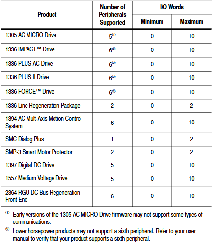
Adaptation scenarios: Compatible with various Allen Bradley SCANPort products, including 1305 AC micro drives, 1336 series inverters (IMPACT/PLUS/FORCE), 1394 multi axis motion control systems, SMC Dialog Plus controllers, etc. Different products support 1-6 peripheral connections, with an I/O word length range of 0-10 words (depending on the product model).
Hardware composition: The core hardware interfaces and components of the module are shown in the table below:
|Component Name | Function Description|
|DIN rail mounting seat | Fixed module and electrically grounded, compatible with 35 × 7.5mm DIN rails (models 199-DR1, etc.)|
|ControlNet coaxial interface (A/B channels) | Connect ControlNet cable taps, supporting redundant/non redundant network configurations|
|Two color LED indicator lights | 4 status lights (ControlNet A/B channels SCANport、 The module itself is used for fault diagnosis|
|SCANPort interface | 8-pin circular mini DIN connector, connected to SCANPort products through a dedicated SCANPort cable|
|ControlNet Node Address Indicator | Press the key to set the node address (0-99), which needs to be powered off and restarted to take effect, ensuring that the address is unique within the network|
|24V DC power interface | Supports multi module Daisy chain power supply, reduces wiring complexity|
|Network Access Port (RJ-45) | To connect ControlNet network devices, a 1786-CP cable and a 1784-KTCX communication card are required|
|RS-232 serial port | Used for parameter configuration and firmware upgrade, requires 1203-SFC serial port cable and terminal simulation software/VT100 terminal|
Installation and electrostatic protection
1. Installation preparation
Tools and equipment: Grounding wristband (included with module), 1/8 inch flathead screwdriver, blunt tool (set node address), ohmmeter, SCANPort cable (such as 1202-C03/C10, up to 10m), ControlNet tap (such as 1786-TPS/TPR, redundant configuration requires 2).
Static protection: The module contains ESD sensitive components, and a grounding wristband must be worn during operation. Refer to Allen Bradley document 8000-4.5.2 "Guidelines for Preventing Static Damage".
2. Installation steps
Set node address: Use a blunt tool to press the "+/-" keys to set a unique address (0-99). It needs to be powered off and restarted to take effect. Avoid using pencils/pens to prevent damage to the switch.
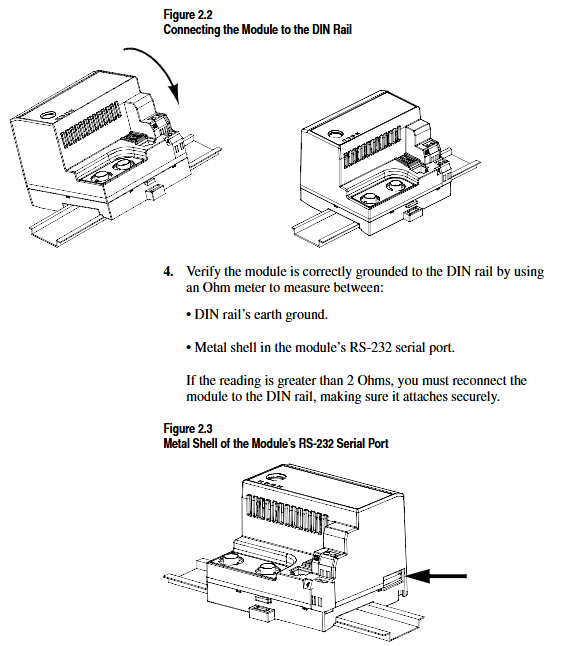
Rail installation: Insert the top hook of the module into the DIN rail, rotate and fasten it, and use an ohmmeter to check the rail grounding (the resistance between the metal shell of the RS-232 port of the module and the rail grounding is ≤ 2 Ω).
Cable connection: Insert the SCANPort cable alignment interface (hear a snap sound); Screw the ControlNet tap into the corresponding A/B channel; 24V DC power supply connection (supports multi module cascade power supply).
Installation verification: After power on, the SCANPort and ControlNet LEDs remain constantly green, and the module LED flashes green (when network configuration is not completed). If the LED status is abnormal, the wiring needs to be checked.
3. Module removal
After power failure, disconnect all cables (SCANPort cables need to be pressed and pulled out), pry the release buckle with a screwdriver, remove the module, and maintain grounding protection throughout the process.
Basic configuration and operation
1. Serial port connection and parameter configuration
(1) Connection preparation
Hardware: 1203-SFC serial port cable (connecting module RS-232 port to PC/terminal).
Software: PC needs to install terminal simulation software (such as Windows HyperTerminal) or use VT100 compatible terminals.
(2) Serial port configuration steps
Software settings: default baud rate of 9600 (parameter 21 can be modified, supports 2400/4800/19.2K/38.4K), data bit 8, no checksum, stop bit 1, no flow control; Simulate to select VT100 mode.
Access main menu: Press Enter to enter the module main menu, supporting 7 functions:
1: Display/edit parameters; 2: Specify parameter number for query; 3: Display event queue; 4: Display current I/O data; 5: Display DF1 protocol statistics; 6: View serial number; 7: Firmware upgrade.
(3) Key parameter configuration
The default parameters of the module support 16 bit logic instructions/status and 16 bit reference/feedback values. When the SCANPort product triggers a fault in PLC programming mode or network failure, the following parameters can be used to adjust the function:
Parameter Number Name Function Description Default Value
4 CMD/Stat enable/disable logical instructions from ControlNet to SCAnport/simulate reference data transfer 1 (enable)
5-8 DataLnk A-D Config Enable/Disable corresponding data link (each channel occupies 2 inputs+2 output words) 0 (disabled)
9-10 Idle/Comm Flt Action PLC programming mode/action in case of network failure (0=fault, 1=zero data, 2=hold last value, 3=fault configuration value) 0 (fault)
11-20 Fault Cfg Logic/Ref/A1-D2 In: The preset values (logic instructions, reference values, data link values) outputted during a fault are 0
21 Serial Port Rate (0=2400, 1=4800, 2=9600, 3=19.2K, 4=38.4K) 2 (9600)
22 Reset Adapter Reset Module (1=Reset, 2=Reset after restoring default parameters) 0 (Ready)
2. Firmware Upgrade (Flash Upgrade)
Prepare the upgrade file (such as cn1-0_61.bin), connect via serial port to enter the main menu, and select "7>Update Flash Program".
Confirm that the SCANPort product is in a safe state (the product will malfunction and shut down during the upgrade), and press Y to start the upgrade.
Select "Send File" from the "Transfer" menu in the terminal software, choose Xmodem for the protocol, and select "Upgrade File Send". The entire process cannot be interrupted, and the module will automatically restart after completion.
ControlNet Network Configuration
1. Configuration tools and prerequisites
Software: RSNetWorx for ControlNet (32-bit Windows application), RSLinx (communication interface).
Hardware: The PC needs to be connected to the ControlNet network through a 1784-KTCX/1784-PCC card or 1770-KFC adapter.
2. Network configuration steps
Enter online mode: Start RSNetWorx, click "Online", automatically scan the network through RSLinx, and select the target ControlNet network.
Module Mapping:
Click on 'Edits Enabled', right-click on the controller (such as PLC-5) and select 'ControlNet Configuration'.
Select the node (module node address) corresponding to the SCANPort product, insert "Device Connection", and configure the unique N-file address for diagnostic/status/data input/output files.
Set input/output size (control I/O enable+2 words, each data link+2 words, range 2-10 words), RPI (request packet interval) ≥ network update time (NUT).
Save and Verify: Save the configuration file and download it to the controller. Set NUT ≥ 5ms, Max Scheduled Address ≥ highest I/O node address, and Max Unscheduled Address ≥ highest network node address in the network properties.
Configuration confirmation: The SCANPort product icon in RSNetWorx displays a gray flag, and the ControlNet LED of the controller and module is constantly green, indicating normal communication.
PLC programming and message communication
1. Ladder diagram programming (RSLogix5)
Implement I/O interaction between the controller and SCANPort product through N-file mapping. Example functions include start stop control, fault clearing, and frequency reference value transmission. Please note:
Logical instruction bit definition: For example, in the 1336 PLUS driver, bit 0=stop, bit 1=start, bit 2=jog, and bit 3=fault clearing. Please refer to the SCANPort product manual for details.
Data scaling: For example, the frequency reference value 0-32767 of the 1305 driver corresponds to 0-maximum frequency, which needs to be transmitted through MOV instructions in the program (such as N7:0 → N13:1).
2. Message communication (PCCC and analog block transmission)
(1) PCCC message
Support PLC-5 Typed Read/Write and encapsulate protocol messages, examples include:
Read 10 SCANPort product parameters (starting parameter 1): target address N10:1, PLC data storage N20:0, Size=10.
Read the complete information of a single parameter (such as parameter 1): target address N30:1, size=20 (including parameter name, unit, maximum value, etc.).
(2) Simulated Block Transfer
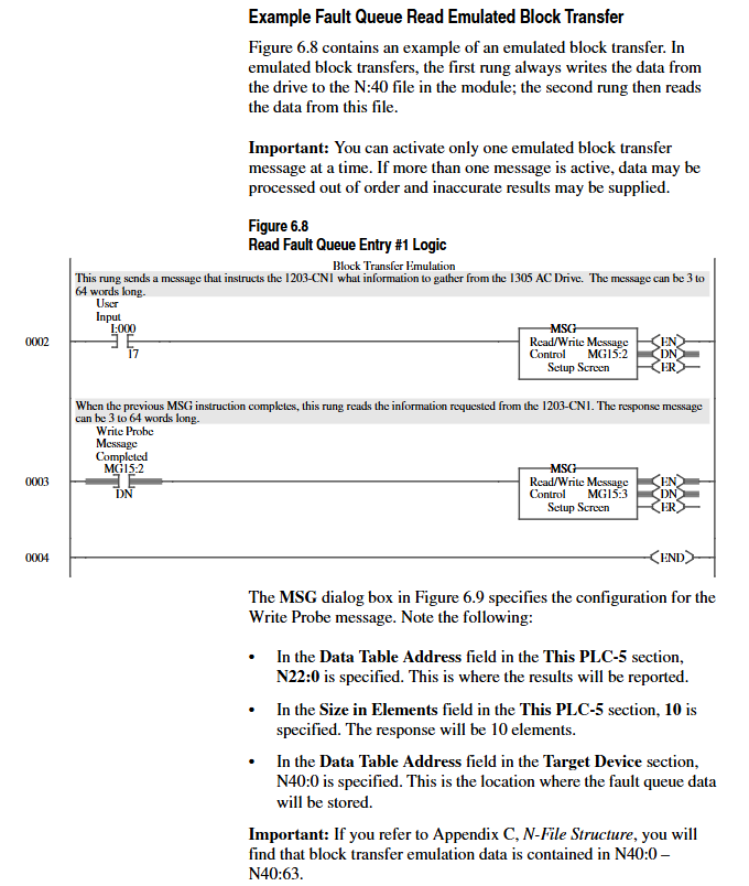
Supports 11 types of commands such as parameter read/write, fault queue query, NVS storage operation, etc., which need to be implemented through 2 MSG instructions (write request first, then read response). Examples include:
Parameter value reading: Request instruction length of 3 words (message length 3, decimal 769, parameter number), respond with parameter value or error code.
Fault queue reading: Request to specify queue number, respond with fault text (displayed in reverse ASCII), fault code, and timestamp (supported by 1336 FORCE).

Troubleshooting and LED diagnosis
1. Interpretation of LED status
The colors and flashing patterns of the four LEDs in the module correspond to different states. The core troubleshooting is as follows:
Solution for LED type status reasons
Check the cable/tap for faults in the red link interface of both ControlNet A/B. Power off and restart, if ineffective, contact after-sales service
SCANPort flashing red SCANPort communication error/data link does not support reconnecting cables, verify module compatibility with product configuration
Module flashing red (3 times) Non volatile storage CRC error check parameters, modify and save at least 1 parameter, then restart
Module flashing green configured I/O but no ControlNet connection confirmed controller network configuration, remap module
2. Event queue and DF1 statistics
Event queue: Select "3>Display event queue" from the main menu to view fault/warning information (graded by severity: I=information, W=warning, S=serious, F=fatal), which can be cleared through "Clr Event Queue".
DF1 statistics: View the number of sent/received packets, undelivered messages, NAK errors, etc., and reset the statistics through "Clear DF1 Counts".
Core specifications
Project parameters
Power supply 24V DC (-20%~+30%), maximum current 250mA
Working environment temperature 0~60 ° C, humidity 5%~95%, no condensation, vibration 2.5g (5Hz~2KHz), impact 30g (working)/50g (non working)
Protection level UL 508/CUL, 6KV contact discharge/8KV air discharge, metal shell required to achieve EMC Class A compliance
- YOKOGAWA
- Reliance
- ADVANCED
- SEW
- ProSoft
- WATLOW
- Kongsberg
- FANUC
- VSD
- DCS
- PLC
- man-machine
- Covid-19
- Energy and Gender
- Energy Access
- Renewable Integration
- Energy Subsidies
- Energy and Water
- Net zero emission
- Energy Security
- Critical Minerals
- A-B
- petroleum
- Mine scale
- Sewage treatment
- cement
- architecture
- Industrial information
- New energy
- Automobile market
- electricity
- Construction site
- HIMA
- ABB
- Rockwell
- Schneider Modicon
- Siemens
- xYCOM
- Yaskawa
- Woodward
- BOSCH Rexroth
- MOOG
- General Electric
- American NI
- Rolls-Royce
- CTI
- Honeywell
- EMERSON
- MAN
- GE
- TRICONEX
- Control Wave
- ALSTOM
- AMAT
- STUDER
- KONGSBERG
- MOTOROLA
- DANAHER MOTION
- Bentley
- Galil
- EATON
- MOLEX
- Triconex
- DEIF
- B&W
- ZYGO
- Aerotech
- DANFOSS
- KOLLMORGEN
- Beijer
- Endress+Hauser
- schneider
- Foxboro
- KB
- REXROTH
- YAMAHA
- Johnson
- Westinghouse
- WAGO
- TOSHIBA
- TEKTRONIX
- BENDER
- BMCM
- SMC
- HITACHI
- HIRSCHMANN
- XP POWER
- Baldor
- Meggitt
- SHINKAWA
- Other Brands
- UniOP
- KUKA
- IBA
- Beckhoff
- ADLINK
-
ADLINK HPCI-14S12U - Industrial Control Backplane 12PCI Backplane PCI-14S Passive Backplane
-
ADLINK PCIe-GIE74C - image acquisition card 4-CH GigE Vision PoE+ Frame Grabber
-
ADLINK PCI-8164 - control card 4-Axis Advanced Motion Controller Board
-
ADLINK PCIe-U304 - 4 Port USB3 PCIe Frame Grabbers USB Screw Hole Card
-
ADLINK PCI-9112 - Multi-Function Data Acquisition Card DAQ Card
-
ADLINK PCI-7432 - 51-12013-0A50 4-CH Isolated Numérique I/O PCI Cartes Digital I/O Card
-
ADLINK PCA-6106P3-0C1 REV.C1 - backplane 6-Slot Passive Backplane Board
-
ADLINK PCI-7224 - 24-CH Opto-Isolated Digital I/O PCI Board
-
ADLINK CPCI-7433R(G) - Digital Input Board Rear I/O CompactPCI Card
-
ADLINK EBP-13E4 - 51-46703-0A30 Industrial PC Backplane Passive Backplane
-
ADLINK PCIE-HDV62 - Image acquisition card High Definition Video Frame Grabber
-
ADLINK EBP-13E4 - 51-46703-0A30 Industrial Backplane Board Passive Backplane
-
ADLINK 90111-B1 / CPCI-6770 - PCB CPU MODULE CompactPCI Single Board Computer
-
ADLINK PCI-7248 - DATA ACQUISITION PCI CARD 48-CH Parallel Digital I/O Board
-
ADLINK PCI-7230 - 51-12003-0a50 board PCI7230 32-CH Isolated Digital I/O Card
-
ADLINK PCI2A000CB - 51-20000-0B30 Multi-Function DAQ Card Baseboard
-
ADLINK PCI-8134-005 - 4-Axis Motion Controller Card
-
ADLINK PCI-7224 - 24-CH Opto-Isolated Digital I/O PCI Card
-
ADLINK PCI-7434 - 64-CH Isolated Digital Output Card
-
ADLINK PCI-8132 - motion control card 2-Axis Servo & Stepper Controller
-
ADLINK PCI-8134 - Motion Controller PCI Card 4-Axis Controller Board
-
ADLINK PCI-8164 - Motion Control Card 51-12406-0A40 4-Axis Controller
-
ADLINK 51-12001-0C20 - Circuit Board Data Acquisition Interface Module Hardware
-
ADLINK NuPR0-840 - industrial control motherboard Full-Size PICMG CPU Board
-
ADLINK PCI-7444 - 51-12023-0A10 card 128-CH Isolated Digital Output Board
-
ADLINK PCI-1612B - data acquisition card 4-Port RS-232/422/485 Serial Communication Card
-
ADLINK PCI-6208V 009 - 8/16-CH 16-Bit Analog Output Cards PCB-I-E-482=6BX3
-
ADLINK NUPRO-935A/LV - industrial control motherboard Full-Size PICMG SBC Board
-
ADLINK PCI-9114DG - Multi-Function DAQ Card Data Acquisition PCI Card
-
ADLINK ACL-7130 - Data acquisition card Isolated Digital I/O Board
-
ADLINK ABX-6300D-4E1-BP - board ABX6300D4E1BP Video Interface Expansion Card
-
ADLINK CPCI-6940 - CPCI-6940/D1539/M16-0(EA)-000E 6U CompactPCI Processor Board
-
ADLINK NuPRO-760 - industrial control motherboard Half-Size PICMG SBC CPU Board
-
ADLINK IMB-M42H (G)-0020 - industrial control motherboard LGA1155 Micro-ATX Mainboard
-
ADLINK RTV-24 / PCI-MP4S - 51-12519-1C30 4-Channel Real Time Video Capture Board
-
ADLINK PCI-8134 - 4-Axis Servo & Stepper Motion Controller Card
-
ADLINK MXC-6101D - V.PC000.002.ST.00 Box PC Configurable Embedded Computer
-
ADLINK PCI-8134A - 51-12421-0A10 Motion Control Card 4-Axis Controller Card
-
ADLINK DIN-100S / DIN-100SA1 - Technology SCSI-II TB 100-PIN Terminal Block Board
-
ADLINK DIN-812M001 / DIN812M001 - 51-14034-0A1 51140340A1 Terminal Module Breakout Interface
-
ADLINK PCI-8164 - Servo motion control 4-Axis Advanced Controller Card
-
ADLINK PCIe-GIE64 - Acquisition card GigE Vision PoE+ Frame Grabber
-
ADLINK M-302 - Industrial control motherboard ATX PC Board Mainboard
-
ADLINK PCI-8134 - Motion Controller PCI Card 4-Axis Controller Board
-
ADLINK PCI-RTV24 - Image capture card Analog Video Frame Grabber
-
ADLINK PCI-8102 - Motion control card 2-Axis Servo & Stepper Controller Board
-
ADLINK PCI-9112 REV.B1 - Card Multi-Function Data Acquisition Card
-
ADLINK HSI-DI32-M-N / HSL-TB32-M-DIN - Discrete I/O MODULE Distributed Automation Module System
-
ADLINK PCI-7296 - IO card REV.A3 96-CH Parallel Digital I/O Card
-
ADLINK DIN-814P-A4 / 814Y - terminal board Motion Control Interface Block
-
ADLINK DIN-814P-A4 - 51-14056-0A10 PCB-I-E-2736=ZA01 Screw Terminal Board Breakout
-
ADLINK M-322 - motherboard Industrial Control Computer Mainboard
-
ADLINK NUPRO-406 REV:B1 - industrial control motherboard Full-Size PICMG CPU Board
-
ADLINK AMP-204C - card DSP-Based 4-Axis Advanced Pulse-Train Controller
-
ADLINK HPCI14S REV.B1 - industrial computer baseboard 14-Slot Passive Backplane
-
ADLINK PCI-7250 - 8-CH Relay Output & 8-CH Isolated DI PCI Card
-
ADLINK EBP-13E2 - baseplate Passive Backplane Industrial Computer Chassis Board
-
ADLINK LPCI-3488A - PCI-GPIB card 51-12801-0A30 acquisition card IEEE-488 Interface Board
-
ADLINK PCI-6216V-GL - 51-12201-0C30 16-CH 16-Bit Voltage Analog Output Card
-
ADLINK ACL-8454 - 16-CH Isolated Digital I/O & 4-CH Counter Card
-
ADLINK HPCI-9S7U - backplane Passive Backplane Compatible with NuPRO-A301 852 841 842
-
ADLINK DAQ-2010-007 - Simultaneous-Sampling Multi-Function Data Acquisition Card
-
ADLINK MP-C154 - 51-64205-0A10 Motion Control Card 4-Axis Controller Board
-
ADLINK MXE-202/mSSD16B/WiFi-BT - Matrix Rugged I/O Platform Embedded Fanless Computer
-
ADLINK CM-920-R-17 - PC/104-Plus Single Board Computer Module Intel Celeron M
-
ADLINK PCI-7250 NSMP - 8-CH Relay Output & 8-CH Isolated DI Card
-
ADLINK PCI-8164 - 4-Axis Motion Controller PCI Card W/ Cable and Breakout Box
-
ADLINK EMX-100 - Ethernet-based 4-axis Motion Controllers Distributed Motion Module
-
ADLINK PCI-8134A - Press control card 4-Axis Motion Controller Board
-
ADLINK M-845EG REV:3.2 - industrial motherboard Pentium 4 Socket 478 Micro-ATX
-
ADLINK PCI-9114A Rev A2 DG - card High-Resolution Multi-Function Data Acquisition Board
-
ADLINK IEC-915GV - REV 1.1 Industrial motherboard Socket 478 CPU Board
-
ADLINK PCI-9111DG(G) - Data Acquisition Card Multi-Function DAQ Card
-
ADLINK HPCI-15S10 REV:B2 - Industrial computer base plate Passive Backplane Board
-
ADLINK NuPR0-840 / NuPR0-840DV - industrial control motherboard Full-size PICMG CPU Board
-
ADLINK RTV-24 / PCI-MP4S - 51-12519-1C30 4-Channel Real Time Video Capture Board
-
ADLINK NUPRO-780 - industrial control motherboard Pentium III Single Board Computer
-
ADLINK PCI-7296 - 0050 card 96-CH Opto-Isolated Parallel DIO Card Set
-
ADLINK NUPRO-780 - industrial control motherboard PICMG Full-Size SBC
-
ADLINK PCI-7248 - 51-12006-0A3 002 Pci 7248 48-CH Parallel Digital I/O Card
-
ADLINK cPCI-6626 - 6U CompactPCI 2.0 Blades i7-2710QE PCB-I-E-2570=9N41
-
ADLINK MXC-6322D(G) - Industrial Fanless Computer
-
ADLINK cPCI-8168-004 - CompactPci NulPC Motion Control Board 51-36402-0A3
-
ADLINK CPCI-7300[G] - COMPACTPCI Digital I/O Card Data Acquisition
-
ADLINK CPCI-6626/2710/M4G - COMPACTPCI COMPUTER BOARD
-
ADLINK cPCI-8168-009 - cPCI NulPC Motion Control Board
-
ADLINK cPCI-6626/2710/M4G - VME CPU Board Computer Board
-
ADLINK CPCI-R6200(G)-0040 - COMPACTPCI CONTROL BOARD
-
ADLINK CPCI-3840/PM18/M1G(G)-3650 - COMPACTPCI CPU Module Single Board Computer
-
ADLINK cPCI-7248 - 48-CH Opto-22 Compatible Digital I/O Module
-
ADLINK DLAP-211-JNX - NVIDIA Jetson Xavier NX Edge AI Inference Platform
-
ADLINK cPCI-3544 - Series 4-Port RS-422/485 Isolated Serial Communications Card
-
ADLINK CM1-86DX3 - PC/104 SBC Stanley Vortex86DX3 CPU 2GB Ram
-
ADLINK DLAP-211-JNX - NVIDIA Jetson Xavier NX Edge AI Inference Platform
-
ADLINK cPCI-3544 - Series 4-Port RS-422/485 Isolated Serial Communications Card
-
ADLINK CM1-86DX3 - PC/104 SBC Stanley Vortex86DX3 CPU 2GB Ram
-
ADLINK PCI-7433 - switch value acquisition card Isolated Digital Input Card
-
ADLINK PCI-9112 - 51-12252-0D20 Multi-Function Data Acquisition Card
-
ADLINK NUPRO-A301 REV:1.4 - industrial control motherboard PICMG Full-Size SBC
-
ADLINK 51-18502-0A10 - Frame Grabber Image Acquisition Interface Card
-
ADLINK PCI-7296 - 51-12009-0A50 PCB-I-E-925=6DX1 96-CH Parallel Digital I/O Board
-
ADLINK PCI-8132 GP A2 - Motion Control Card 2-Axis Servo & Stepper Controller
-
ADLINK PCI-7442 - switch quantity card data acquisition card 64-CH Isolated Card
-
ADLINK HPX-13S4 - baseboard PICMG 1.3 Passive Backplane Chassis Baseplate
-
ADLINK NuPRO-590 / NTC-567-ZM-F36 - Single Board Computer PCB-I-E-1853=9L21 Half-Size SBC
-
ADLINK PCIe-8332 - 16-axis plate Motion Control Hardware Card
-
ADLINK NuPRO-775 REV.B1 - motherboard Pentium 4 Full-Size PICMG SBC
-
ADLINK PXI-3920 - Embedded Controller 3U PXI cPCI System Intelligence Board
-
ADLINK PCI-8134 - driver card motion control card 4-Axis Controller Board
-
ADLINK HSL-DI32-M-N-011 / HSL-TB32-M-DIN - Digital Input & Base Module PLC Distributed I/O System
-
ADLINK PCI-6216V-206 / PCI-208V 009 - 16 CH 16bit analog output card
-
ADLINK NuPro-E330 - 51-41805-0A20 PCB Single Board Computer Host Board
-
ADLINK PCI-1622C - Card 8-Port RS-232/422/485 PCI Serial Communication Board
-
ADLINK PCIe-7432 - 51-18402-0A10 Carte PCIe Avec Plage D'Entrée Élevée Isolated DIO Card
-
ADLINK PCI-7250 - PCI Acquisition Card 8-CH Relay Output Isolated DI Card
-
ADLINK PCI-7230 - 32-CH Isolated Digital I/O Card
-
ADLINK PCI-8164 - PCB 4-Axis Motion Controller Card
-
ADLINK PCI-7854 - Collection card High-Speed Link Distributed Motion Controller
-
ADLINK NuPRO-935A/LV - industrial control computer motherboard Full-Size PICMG SBC
-
ADLINK IMB-M40H - motherboard IH61-AA4 1155 LGA1155 Micro-ATX Mainboard
-
ADLINK PCI-7248 - Linhua 51-12006-0A40 48-CH Parallel Digital I/O Card
-
ADLINK HPCI-14S12U - Linhua industrial computer baseboard Passive Backplane
-
ADLINK PCI-8132 Rev.A2 - 2-Axis Servo & Stepper Motion Controller Card
-
ADLINK ACL-8111 - ISA card Multi-Function DAQ Card
-
ADLINK ACL-8111 - ISA card Multi-Function Data Acquisition Board
-
ADLINK PCI-7200 REV.A3 - Digital I/O card 12MB/s High-Speed Parallel Digital I/O
-
ADLINK PCI-7296 REV.A3 - 96-CH High-Density Opto-Isolated DIO Card
-
ADLINK PCI-7434 - 64-CH Isolated Digital Output Card

K-JIANG

Add: Jimei North Road, Jimei District, Xiamen, Fujian, China
Tell:+86-15305925923