
K-WANG


Allen Bradley DeviceNet Communication Module (1203-GK5/1336-GM5)
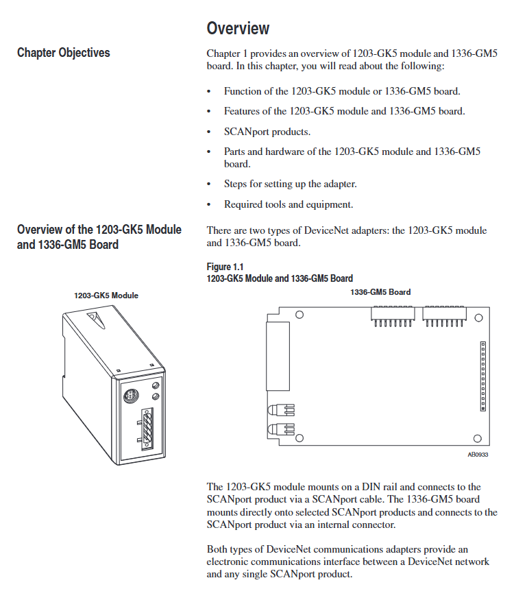
Features 1203-GK5 module 1336-GM5 board
Physical form independent module embedded board
Installation method: 35 × 7.5mm DIN rail mounting (compatible with 199-DR1 and other models of rails) directly installed inside specific SCANPort products (such as 1336 series drives)
Connection method: 8-pin mini DIN interface+SCANPort cable (up to 10m), 14 pin internal SCANPort connector (no additional cables required)
Most SCANPort products, such as 1305/1336 PLUS/1394, are only compatible with 1336 series drives (compatibility needs to be confirmed for some low-power models)
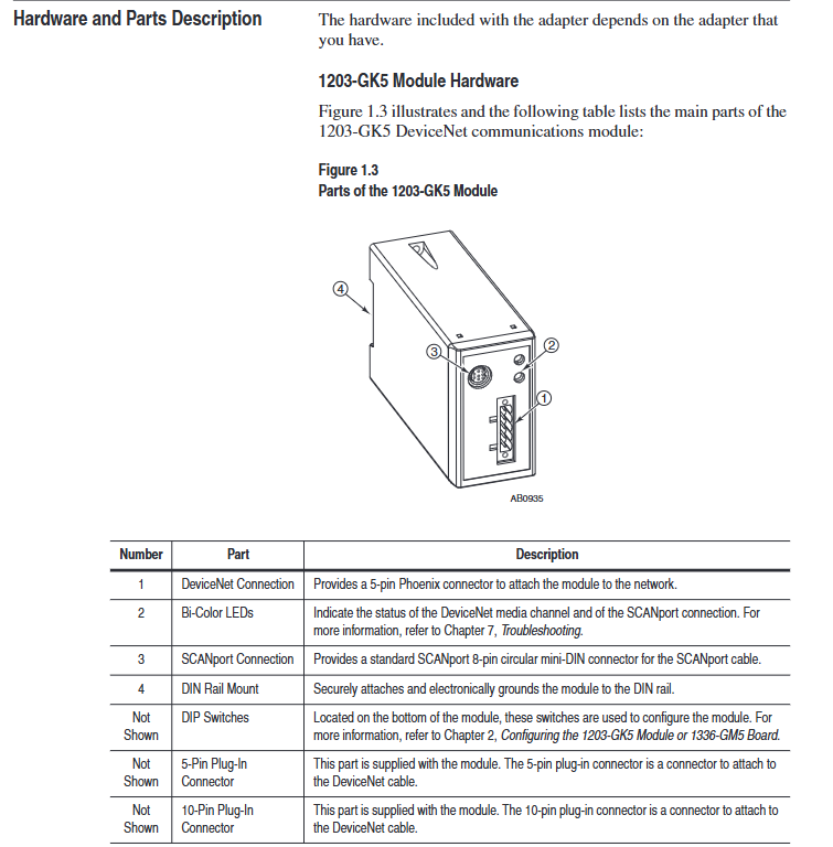
The packaging accessories include 5-pin/10 pin Phoenix connectors, DIN rail buckles with grounding wristbands, installation screws, nylon support columns, and communication housings
Allen Bradley DeviceNet Communication Module (1203-GK5/1336-GM5)
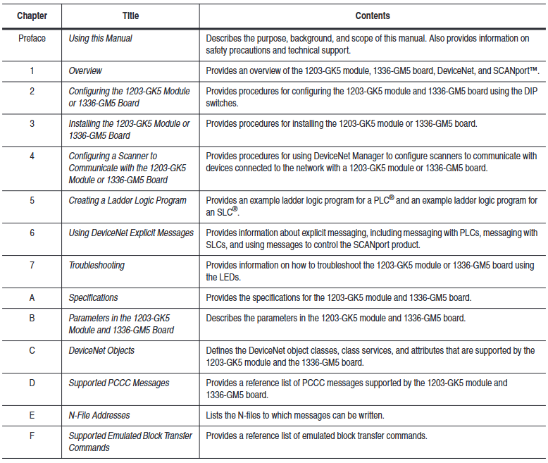
Product Overview and Core Positioning
1. Product types and differences
Both devices are DeviceNet communication adapters, with the same core functions but different forms and installation methods. The specific differences are shown in the table below:
Features 1203-GK5 module 1336-GM5 board
Physical form independent module embedded board
Installation method: 35 × 7.5mm DIN rail mounting (compatible with 199-DR1 and other models of rails) directly installed inside specific SCANPort products (such as 1336 series drives)
Connection method: 8-pin mini DIN interface+SCANPort cable (up to 10m), 14 pin internal SCANPort connector (no additional cables required)
Most SCANPort products, such as 1305/1336 PLUS/1394, are only compatible with 1336 series drives (compatibility needs to be confirmed for some low-power models)
The packaging accessories include 5-pin/10 pin Phoenix connectors, DIN rail buckles with grounding wristbands, installation screws, nylon support columns, and communication housings
2. Core functions and features
Communication conversion: Convert DeviceNet messages to SCAnport protocol, supporting polling I/O (logical instructions/reference values/feedback values) and explicit messages (parameter read/write, fault query), DeviceNet speed supports 125K/250K/500Kbps.
Flexible configuration: Set node addresses (0-63), data rates, Datalink enablement, and fault response strategies through DIP switches; Support fault node recovery (SW2-7/8 needs to be set to ON, and the offline node address needs to be modified with software).
Status monitoring: Dual color LED indicator lights (DeviceNet network status, SCANPort connection status) provide real-time feedback on communication and device health status.
Compatibility: Compatible with various SCANPort products, such as 1305 AC micro drives, 1336 series frequency converters (IMPACT/PLUS/FORCE), 1394 multi axis motion systems, etc. Most products support 1-6 peripheral connections, with an I/O word length range of 2-10 words (please refer to the product manual for details).
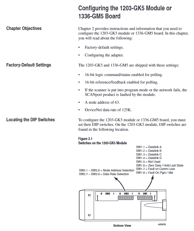
DIP switch configuration (core pre steps)
The DIP switches of the two devices are in the same layout (1203-GK5 is at the bottom and 1336-GM5 is at the edge of the board). They need to be adjusted after power off to take effect after power on. The specific configuration items are as follows:
1. Node address (SW2-1~SW2-6)
Function: Set the DeviceNet network node address (0-63), default is 63, and ensure that the address is unique within the network.
Configuration rule: Binary encoding, SW2-1 is the lowest bit (1), SW2-6 is the highest bit (32), for example, address 3 corresponds to "000011" (SW2-1/SW2-2 is set to ON, the rest are set to OFF).
2. Data rate (SW2-7~SW2-8)
Function: Define DeviceNet communication rate, default 125Kbps, configuration rules are as follows:
|SW2-8 (high bit) | SW2-7 (low bit) | Data rate | Description|
|0 | 0 | 125Kbps | Default value|
| 0 | 1 | 250Kbps | - |
| 1 | 0 | 500Kbps | - |
|1 | 1 | Software configuration | Requires setting through DeviceNet Manager (supports fault node recovery)|
3. Data link (SW1-1~SW1-4)
Function: Enable Datalink (2 input+2 output words per channel, up to 4 channels), default fully disabled, configuration rules:
|Switch | Function | 0 (OFF) | 1 (ON)|
|SW1-1 | Datalink A | Disabled | Enabled|
|SW1-2 | Datalink B | Disabled | Enabled|
|SW1-3 | Datalink C | Disabled | Enabled|
|SW1-4 | Datalink D | Disabled | Enabled|
Attention: It is necessary to ensure that the SCANPort product supports Datalink and that the same Datalink is not occupied by other adapters.
4. Fault response (SW1-6~SW1-8)
Function: Configure device behavior in case of network failure (communication interruption) or controller idle (programming mode), triggering SCANPort product failure by default. Configuration rules:
|Switch | Function | 0 (OFF) | 1 (ON)|
|SW1-8 | Programming/Idle Fault | Triggered Fault | Non Triggered Fault|
|SW1-7 | Communication interruption fault | Trigger fault | No trigger fault|
|SW1-6 | Standby behavior | Output zero data | Maintain last state|
Safety Reminder: Modifying fault response requires risk assessment to avoid personal injury or equipment damage caused by continuous operation of the equipment.
Installation process and electrostatic protection
1. General safety requirements
Static protection: Modules/boards contain ESD sensitive components, and grounding wristbands must be worn during operation, refer to Rockwell document 8000-4.5.2 "Anti static Damage Guide".
Power off operation: Before installing the 1336-GM5 board, all power sources of the SCANPort product must be disconnected to avoid electric shock; The installation of 1203-GK5 requires disconnecting the DeviceNet network power supply.
2. Installation steps for 1203-GK5 module
Rail mounting: Insert the top hook of the module into the DIN rail, rotate and fasten it, and use an ohmmeter to check the grounding (the resistance between the metal shell of the RS-232 port of the module and the rail grounding is ≤ 2 Ω).
Cable connection:
DeviceNet: 5-pin connector (point-to-point) or 10 pin connector (daisy chain), wired by color (red=PWR, white=CAN_S, blue=CAN_L, black=COM, bare wire=shielded).
SCAnport: Insert the 8-pin mini DIN interface into the cable and confirm installation with a snap sound. The cable length should be ≤ 10m and kept away from high-power cables to prevent interference.
Power on verification: The SCANPort LED is constantly green, and the DeviceNet LED is flashing green (no connection established). If there is an abnormality, refer to the troubleshooting section.
3. Installation steps for 1336-GM5 board
Preparation: Disconnect the power supply of the drive, remove the casing, and install 4 nylon support columns on the drive main control board.
Card fixing: Align the 14 pin pin of the card with the SCANPort interface and insert it, then fix it with 4 screws (to avoid damaging the card due to over tightening).
DeviceNet wiring: Connect 5-pin Phoenix connectors by color, insert them into the card interface, and tighten the screws.
Power on verification: Install the communication enclosure, restore the driver power, keep the SCANPort LED on green, and the DeviceNet LED flashing green.
DeviceNet Network Configuration (DeviceNet Manager)
1. Configuration tools and prerequisites
Software: DeviceNet Manager (Windows application) or RSNetWorx for DeviceNet, requires a 1784-PCD card or 1770-KFD adapter to connect the PC to the DeviceNet network.
Prerequisite: DIP switch configuration has been completed, module/board has been connected to the network, and RSLinx (communication interface software) has been installed on the PC.
2. Core configuration steps
(1) Online mode connection
Start DeviceNet Manager, select "Utilities>Set Up Online Connection", and choose the corresponding driver (such as 1770-KFD).
Configure communication ports (COM1/COM2), baud rate (default 38400bps), PC node address (avoid 63), network data rate (consistent with DIP switch), click "OK" to enter online mode.
(2) Create EDS file (initial configuration)
Select "Who>Network Who" to scan the network, double-click on unrecognized devices (displaying the universal icon), and a prompt "Create EDS file" will pop up. Click "Yes".
Click on 'Load from Device', enter the module/board node address, automatically load the device description, select the device icon (such as 1336. BMP) and SCANPort adapter icon (SCANPORT. BMP).
Enable "Polled Connection", set the I/O size (default 4 bytes, formula: 4+number of enabled Datalinks x 4), click "OK" to save, and rescan the network to confirm that the device icon is displayed normally.
(3) Configure PLC/SLC scanner
Taking 1771-SDN (PLC scanner) as an example:
Double click the scanner icon to enter "1771-SDN Module Configuration", click "Edit Scan List", select "Add Devices From>Who", and drag the target node into the scan list.
Select the node, click "Edit I/O Parameters", and set the polling I/O size (same as EDS configuration) and polling rate (Every Scan/Background).
Click on "Auto Map" to configure the storage address for input/output data (such as PLC N90/N100 files), and click "Map" to complete the mapping.
Select "Save To>SDN", download the configuration to the scanner, prompt "Scanner offline for 5-10 seconds", confirm and complete the configuration.
(4) Save and Verify
Save configuration file (for PLC) Used for SL7 and SLC SL4), Before exiting, confirm that the DeviceNet LED is always green (indicating connection establishment) and the SCANPort LED is always green (indicating normal communication).
Programming and Communication Implementation
1. Ladder diagram programming (RSLogix)
Implementing SCAnport product control through polling I/O requires N-file mapping (input=SCAnport → DeviceNet, output=DeviceNet → SCAnport). Example functions are as follows:
Start stop control: 1336 PLUS driver logic instruction bit definition (bit 0=stop, bit 1=start, bit 2=jog, bit 3=fault clearing), writes the operation signal to the output N-file (such as N10:1) through MOV instruction.
Reference value transmission: The frequency reference value 0-32767 corresponds to 0-maximum frequency, and N7:0 (operator set value) is written to N10:2 (driver reference value) through MOV command.
Status monitoring: Read the drive status bits (bit 1=running, bit 8=fault) from the input N-file (such as N9:1) and output them to the operator display terminal (such as O: 000).
2. Explicit message communication
Support explicit message reading and writing of parameters and fault queries through DeviceNet, following the 8:16 format (8-bit class field+16 bit instance field). The core rules are as follows:
(1) PLC scanner (1771-SDN)
Write the message to the scanner buffer (10 available buffers) using 64 block transfer write (BTW), and retrieve the response through 64 block transfer read (BTR) after completion.
Message format: including transaction ID (1-255), command (1=execute, 2=query status), port (0=channel A), size (in bytes), service code (e.g. 0x0E=get attribute), node address, class/instance/attribute.
(2) SLC scanner (1747-SDN)
Write the message to the M0 file (e.g. M0: 1.224), the scanner processes it and stores the response in the M1 file. After reading, send a "delete command" (command 4) to release the buffer.
Example: Read the number of fault queues (class 0x97, instance 0, attribute 1), store the response data in N20:53, and return the number of fault queue entries.
(3) Safety Tips
Frequent parameter writing through explicit messages can shorten the lifespan of EEPROM. It is recommended to use Datalink to handle high-frequency parameter modifications (Datalink does not write to EEPROM).
- YOKOGAWA
- Reliance
- ADVANCED
- SEW
- ProSoft
- WATLOW
- Kongsberg
- FANUC
- VSD
- DCS
- PLC
- man-machine
- Covid-19
- Energy and Gender
- Energy Access
- Renewable Integration
- Energy Subsidies
- Energy and Water
- Net zero emission
- Energy Security
- Critical Minerals
- A-B
- petroleum
- Mine scale
- Sewage treatment
- cement
- architecture
- Industrial information
- New energy
- Automobile market
- electricity
- Construction site
- HIMA
- ABB
- Rockwell
- Schneider Modicon
- Siemens
- xYCOM
- Yaskawa
- Woodward
- BOSCH Rexroth
- MOOG
- General Electric
- American NI
- Rolls-Royce
- CTI
- Honeywell
- EMERSON
- MAN
- GE
- TRICONEX
- Control Wave
- ALSTOM
- AMAT
- STUDER
- KONGSBERG
- MOTOROLA
- DANAHER MOTION
- Bentley
- Galil
- EATON
- MOLEX
- Triconex
- DEIF
- B&W
- ZYGO
- Aerotech
- DANFOSS
- KOLLMORGEN
- Beijer
- Endress+Hauser
- schneider
- Foxboro
- KB
- REXROTH
- YAMAHA
- Johnson
- Westinghouse
- WAGO
- TOSHIBA
- TEKTRONIX
- BENDER
- BMCM
- SMC
- HITACHI
- HIRSCHMANN
- XP POWER
- Baldor
- Meggitt
- SHINKAWA
- Other Brands
- UniOP
- KUKA
- IBA
- Beckhoff
- ADLINK
-
Beckhoff EP9224-0037 - 4-Channel Power Distribution Box EtherCAT
-
Beckhoff CX2900-0026 - Solid State Flash Memory Card 20GB CFast
-
Beckhoff BK7500 - SERCOS Interface Fieldbus Bus Coupler Terminal
-
Beckhoff Ep2328-0002 - 4-Channel Input 4-Channel Output EtherCAT Box IP67
-
Beckhoff CX1020-0111 - Controller Kit Combo Interface Modules
-
B&R X20AI2237 - X20 System Analog Input Interface Module
-
Beckhoff CP2221-0010 - Multi-Touch Built-In Panel PC Touchscreen
-
Beckhoff CX1500-M310 - Fieldbus Master Interface Module 24V
-
Beckhoff CX2100-0904 - Power Charging Module Smart UPS Extension
-
Beckhoff CP3918-0000 - Multi-Touch Control Panel 18.5-Inch Monitor
-
Beckhoff CP2915-0000 - 15-Inch Multi-Touch Built-In Control Panel
-
Beckhoff CP7037-1027 - HMI Industrial Control Panel Built-In PC
-
Beckhoff EL3152 - 2-Channel Analog Input Terminal 4-20mA EtherCAT
-
Beckhoff CP6607-0000-0020 - 5.7-Inch Built-In Panel PC HMI Touch
-
Beckhoff EJ1809-0000 - 16-Channel Digital Input Pluggable Signal Level Terminal
-
Beckhoff AM8563-0N10-0000 - Synchronous Servo Motor
-
Beckhoff AX2006-S60600-520 - Compact Servo Drive Inverter
-
Beckhoff AM8053-0K20-0000 - Servo Motor with Planetary Gearbox AG3210
-
Beckhoff AM8042-0FH1-0000 - Synchronous Servo Motor
-
Rexroth R911338600 - IndraControl V HMI Terminal Beckhoff PCI Card FC9002
-
Beckhoff AX5125-0000 - 3 Phase Industrial Servo Drive 1000Hz
-
Beckhoff EP2328-0002 - 4-Channel Digital Input 4-Channel Output EtherCAT Box
-
B&R 7CP476-02 - System 2005 RTD CPU Module 3IF681.86 Interface
-
Beckhoff AX8620-0000-0000 - Power Supply Module Axis Drive System
-
Beckhoff CX1010-0111 - PLC Module CPU Controller 24V
-
Beckhoff AM8043-0H10-0000 - Synchronous Servo Motor
-
Beckhoff C6240-1009 - Control Cabinet Industrial PC Mainframe
-
Beckhoff BX8000-0000 - Bus Terminal Controller HW 4.4 Standalone
-
Beckhoff CP7721-1089-0020 - 12.1-Inch Touch Screen HMI Panel PC
-
Beckhoff CP7132-0001 - Industrial Built-In Panel PC Screen
-
Beckhoff CP2912-0010 - Multi-Touch Built-In Control Panel Display
-
Beckhoff CP2915-0000 - 15-Inch Multi-Touch Built-In Control Panel
-
Beckhoff AM8532-1EN0-0000 - Synchronous Servo Motor
-
Beckhoff AX5203-0000 - 2-Channel Digital Compact Servo Drive
-
Beckhoff CX2020-0141 - Embedded PC Core CPU Module
-
Beckhoff CP6832-0002-0010 - Built-In Industrial Control Panel Display
-
Beckhoff CX5020-0112 - Embedded PC CPU Control Module
-
Beckhoff CX5140-0175 - 4GB Embedded PC CPU Unit 24V
-
Beckhoff EL3681-0030 - Digital Multimeter Calibration Terminal EtherCAT
-
Beckhoff CP7201-1000-0000 - Industrial PC Touch Screen HMI Monitor
-
Beckhoff CP7232-1001-0000 - Industrial Panel PC Touch Screen
-
Beckhoff C6930-1032-0040 - Control Cabinet Industrial PC System
-
Beckhoff AX5125-0000 - 3 Phase Industrial Servo Drive 1000Hz
-
Beckhoff CP3916-1424-0000 - Multi-Touch Built-In Control Panel
-
B&R 1900071142 - Lemoine Fieldbus Communication Interface Module
-
Beckhoff EL2872 - 16-Channel Ribbon Cable Digital Output Terminal
-
Beckhoff CX2030-0120 - Embedded PC CPU Base Module Controller
-
Beckhoff CP3919-0000 - 19-Inch Multi-Touch Control Panel Touchscreen
-
Beckhoff AX5101-0000-0202 - Servo Driver Compact Intelligent Drive 180V
-
Beckhoff CX5130-0135 - Embedded PC Controller Module
-
Beckhoff CP3719-1061-0010 - Multi-Touch Panel PC Outer Housing Enclosure
-
Beckhoff CP3919-1033-0000 - 19-Inch Touch Industrial Panel Keyboard
-
Beckhoff CX5020-0111 - Embedded PC PLC CPU Module
-
Beckhoff FC5102-0000 - 2-Channel CANopen PCI Control Board Card
-
Beckhoff CX9001-1101 - Embedded PC CPU Network I/O System Module
-
Beckhoff CX1100-0920 - Smart Position Sensor Interface Module
-
B&R 4P3040.01-490 - Operator Panel PLC Interface Communication Module
-
Beckhoff CP2612-0000 - Dual-Touch Built-In Panel PC HMI
-
Beckhoff CP7002-1043-0010 - Touchscreen Display HMI Panel Terminal
-
Beckhoff CX9020-0115 - Embedded PC Controller Module
-
Beckhoff CX5140-0155 - 4GB Embedded PC CPU Module Die Industry
-
B&R 7DI435.7 - System 2005 Universal Digital Input Output Module
-
Bihl+Wiedemann BWU1568 - AS-i Master to Profibus Gateway Module
-
Beckhoff C6920-0070 - Control Cabinet Industrial PC 8GB Win 10
-
B&R X20AI2322 - 2-Channel Temperature Analog Input Module
-
Beckhoff CP2912-0000 - 12-Inch Touchscreen Display Monitor Screen
-
Beckhoff CP6022-1001-0010 - 15-Inch Built-In Control Panel
-
Beckhoff AM8031-0D10-0000 - Synchronous Servo Motor
-
Beckhoff CX5010-0111 - Embedded PC Controller CPU Module
-
Beckhoff CP7232-1000-0000 - Industrial Panel PC Touch Display Screen
-
Beckhoff CP7802-0011-0000 - 15-Inch Industrial Touchscreen Control Panel
-
Beckhoff C6320 - Control Cabinet Industrial PC
-
Beckhoff CX1030-0012 - Basic CPU Module Windows CE 6.0
-
Beckhoff CP2919-0000 - Installation Multi-Touch Control Panel
-
Beckhoff CX1020-0000 - Controller Set Stack System Pack
-
B&R 3DO480.6 - System 2005 Digital Output Module
-
Beckhoff EL3101 - 1-Channel Analog Input Terminal Differential +/-10V
-
Beckhoff AX8108-0200-0000 - Axis Feed Module Servo Drive
-
Beckhoff CP7802-1241-0010 - 15-Inch Industrial Touchscreen Control Panel
-
Beckhoff FC2002-0000 - 2-Channel Lightbus Data Acquisition PCI Card
-
Beckhoff CX5120-0155 - 2GB Embedded PC Intel Atom Controller
-
Beckhoff Cx9020-0111 - 1GB Basic CPU Module Embedded PC
-
Beckhoff CP6901-0001-0000 - 12-Inch Economy Built-In Control Panel
-
Beckhoff CX9020-0111 - Embedded PC CPU Basic Module
-
Beckhoff CX5130-0100 - 4GB Embedded PC CPU Module
-
Beckhoff CP2715-0010 - Multi-Touch Built-In Panel PC
-
Beckhoff CX2033-0175 - Embedded PC CPU Module Core i7
-
Beckhoff CP7201-1000-0000 - 12-Inch Touchscreen Panel PC AMAT Green Box
-
Beckhoff EL4038 - 8-Channel Analog Output Terminal 0-10V EtherCAT
-
Beckhoff CP6802-0000-0000 - Built-In Control Panel HMI Screen
-
Beckhoff CP6500-1012-0060 - Control Cabinet PC Interface Unit
-
Beckhoff FC5202-0000 - 2-Channel DeviceNet Master PCI Interface Card
-
Beckhoff CP6606-0001-0020 - 7-Inch Economy Panel PC Touch
-
Beckhoff CP2921-0010 - Multi-Touch Integrated Control Panel Display
-
Beckhoff CP7802-0001-0010 - 15-Inch Touch Screen Control Panel HMI
-
Beckhoff C6920-0050 - Control Cabinet Industrial PC
-
Beckhoff BK9105 - EtherNet/IP Bus Coupler Network Interface
-
Beckhoff 31 Modules - Bus Terminal Slice I/O Lot Assortment
-
Beckhoff CX2020-0120 - Embedded PC Basic CPU Module 8GB CFast Card
-
Beckhoff CP7001-0000 - HMI Control Panel Touch Screen
-
B&R 7EX484.50-1 - System 2005 Controller Base Module Slots
-
Beckhoff EK1322 - 2-Port EtherCAT P Extension Feed-In Terminal
-
Beckhoff CP6606-0001-0020 - 7-Inch Single-Touch Economy Panel PC
-
Beckhoff CP6607-0001-0000 - Economy Installation Operator Panel PC 5.7-Inch
-
Beckhoff AX5103-0000-0200 - Digital Compact Servo Driver 3 Phase
-
Beckhoff CP7802-0001-0010 - 15-Inch Touch Screen Control Panel
-
Beckhoff AX8620 - Power Supply Module Axis System
-
Beckhoff CX2030-0121 - Embedded PC Controller Module
-
Beckhoff CP6606-0001-0020 - 7-Inch Economy Panel PC Touch Screen
-
Beckhoff CX2030-0121 - Embedded PC CPU Module Windows Standard 7
-
Beckhoff BX3100-0000 - PROFIBUS DP Bus Terminal Controller
-
Beckhoff CX1020-0000 - Controller Set with Power Supply Unit
-
Beckhoff EK1100 - EtherCAT Coupler Terminal Module Set
-
Beckhoff CP7002-1043-0010 - HMI Display Panel with Control Panel Bracket
-
Beckhoff AM8031-0D10-0000 - Synchronous Servo Motor
-
Beckhoff CX5130-0175 - Embedded PC 4GB RAM Controller
-
Beckhoff CX5130-0155 - Embedded PC Automation Controller
-
Beckhoff C6930-0010 - Control Cabinet Industrial PC Core Duo
-
Beckhoff CP3924-0000 - Multi-Touch Control Panel Display
-
Beckhoff AM8023-0F20-0000 - Synchronous Servo Motor
-
B&R KL3362 - Bus Terminal Thermocouple Input Module
-
Beckhoff AL2006-0000-0000 - Linear Servo Motor Three Phase
-
Beckhoff CX5140-0155 - Embedded PC CPU Controller Module
-
Beckhoff FC9002 - Ethernet PCI Network Interface Card
-
Beckhoff CP7203-0021-0040 - Built-In Panel PC 19-Inch Touch Screen
-
Beckhoff C6930-0020 - Control Cabinet Industrial PC HDD CF Card
-
Beckhoff CX2900-0033 - Memory Card CFast Storage
-
Beckhoff CP6201-0001-0020 - Built-In Panel PC Display

K-JIANG

Add: Jimei North Road, Jimei District, Xiamen, Fujian, China
Tell:+86-15305925923