
K-WANG


Allen Bradley 1391-DES series digital AC servo drive
Allen Bradley 1391-DES series digital AC servo drive
Basic information of the driver
Product positioning and functionality
1391-DES is a digital programmable single axis AC servo drive that is compatible with Allen Bradley 1326 series AC servo motors. It is mainly used in closed-loop positioning systems such as machine tools and automation equipment (such as IMC S-class and MAX controllers), and supports speed and torque control modes.
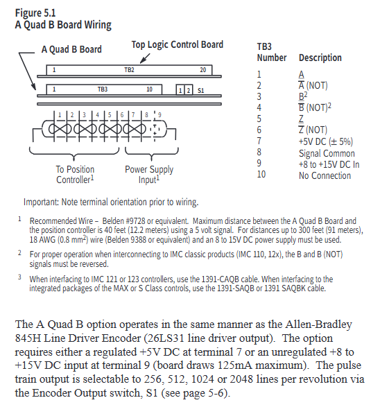
Core advantage: It can enable the 1326 motor to exceed the rated speed by 33% -50%, improving equipment accuracy and production efficiency; Equipped with encoder output (AQB), providing position feedback signals of 256/512/1024/2048 lines per revolution, compatible with positioning controllers.
Model and Key Parameters
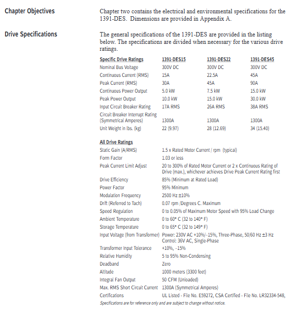
Model classification: Divided by continuous current, it is 1391-DES15 (15A), 1391-DES22 (22.5A), and 1391-DES45 (45A), all of which have the same physical dimensions but different electrical parameters.
Core electrical parameters: rated DC bus voltage of 300V DC, peak current twice the continuous current (such as DES45 peak 90A), modulation frequency of 2500Hz ± 10%, speed regulation accuracy of 0-0.05% (under 95% load variation), operating temperature of 0-60 ° C, no need to reduce capacity at altitude ≤ 1000 meters.
Standard configuration and optional features
Standard functions: Input transient voltage protection, built-in circuit breaker, DC bus shunt regulator (dissipating regenerative energy), 2-row LCD display and programming panel, torque feedforward differential input, microprocessor control board (easy to disassemble and troubleshoot).
Optional functions: Contactor auxiliary switch (for motor braking control or status indication), external shunt resistor (suitable for high regenerative energy scenarios, such as optional 386W external resistor for 22.5A drivers), speed/current monitoring output, anti backlash control, linear acceleration/deceleration module (CR-APG-001, supports 4 preset speeds).
Working principle
Core Circuit and Energy Processing
Power Conversion: Convert 3-phase 50/60Hz AC power into 300V DC bus voltage through a rectifier bridge, and then output variable voltage AC power through a PWM inverter to control motor speed and torque.
Regenerative braking: The regenerative energy generated during motor deceleration will increase the DC bus voltage. When the shunt regulator detects that the voltage exceeds the threshold (386.4V DC), it triggers the chopper transistor to conduct, converting the energy into thermal energy through the braking resistor to avoid bus overvoltage tripping (overvoltage protection threshold 405V DC).
control logic
Closed loop control: By using a motor resolver (rotary transformer) to provide feedback on the rotor position, combined with speed/torque commands, and adjusting through current and speed loops, precise control is achieved; The current loop adopts analog control, and the speed command supports ± 10V DC analog input.
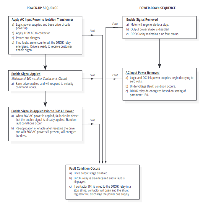
Start stop mode: includes three modes: dynamic braking (bus discharge braking when the contactor is disconnected), regenerative braking (reverse torque braking when the enable signal is disconnected), and free parking (driver disconnection output in case of fault, motor inertia parking).
Installation and wiring
Installation requirements
Environment: It needs to be installed in a closed cabinet, and ventilation should be filtered/cooled to avoid oil mist, dust, and corrosive gases; Vertical installation, distance between single driver and motor ≤ 3m, distance between main driver and frequency converter ≤ 3m when multiple drivers, distance between sub drivers and main drivers ≤ 1.5m, equipment spacing ≥ 304.8mm (to ensure heat dissipation).
Grounding: The driver housing needs to be reliably grounded, and signal grounding (such as resolver, control signal) should use a "star grounding" to avoid introducing noise into the grounding loop.
Wiring specifications
Power wiring: The motor power lines (TB5-1~3) and input power lines (TB5-4~6) need to be twisted pair, separately threaded through pipes, and the wire diameter should refer to the manual (such as 8AWG/6mm ² for DES45); The external shunt resistors (TB5-8~10) need to be matched according to the model (for example, a 45A driver requires an external 5 Ω resistor).
Signal wiring: Control signals such as speed command (TB2-1~2), enable signal (TB2-9~10), reset signal (TB2-11), etc. require 18AWG twisted pair cable with a distance of ≥ 304.8mm from the power line; resolver wiring (TB1-1~10) requires shielded wire with the shielding layer grounded at one end.
Switch and jumper settings
Split regulator duty cycle switch (SW1): adjusts the overheat protection threshold of the braking resistor, and different drivers correspond to different gears (such as setting it to "F" gear when DES22 is equipped with an external resistor).
AQB encoder output switch (S1): Select the number of output lines (256/512/1024/2048), which should match the parameters of the positioning controller (such as halving the number of lines for IMC classic controllers).
Programming and Debugging
Parameter hierarchy and operation
The parameters are divided into three levels: View level (only viewing the operating status, such as speed and current), Modify level (configuring system parameters, such as speed limit and current loop gain), and Maintenance level (advanced parameters, such as inertia compensation and friction compensation), which need to be unlocked through specific key combinations (such as simultaneously pressing the up/down/left arrow+Enter key for Maintenance level).
Core parameters: simulated speed gain (parameter 211, default 500rpm/V, can be calculated based on "maximum motor speed/maximum command voltage"), speed limit (parameters 144/145, default 10% higher than motor rated speed), current limit (parameters 156/157, default 300% motor rated current).
Start debugging process
Preliminary inspection: After confirming that the wiring is correct, power on to verify that the control voltage (± 12V DC,+5V DC) and bus voltage (300V DC) are normal and there are no fault alarms.
Guided start: When powered on for the first time, the driver automatically guides the motor model selection, rotation test (verify motor wiring, rotate clockwise/counterclockwise for 5 seconds each), and zero speed offset calibration (automatically eliminate command offset).
Auto Tune: Starting with parameter 190, the driver automatically measures the system inertia and friction coefficient, calculates the optimal speed loop gain (Kp/Ki), and is suitable for most scenarios; Manual tuning requires adjusting parameters 168 (proportional gain) and 169 (integral gain) to control the speed response overshoot within 20% -30%.
Troubleshooting and Maintenance
fault diagnosis
Fault indication: Front LED light (STATUS light flashing red=fault, green constant light=normal; ENABLE light on=driver enabled), LCD displays specific fault codes (such as "amp overttemp"=driver overheating, "resolver loss"=rotary transformer fault).
Common troubleshooting:
Overvoltage fault: Check whether the input voltage and shunt resistor are open circuited/selected incorrectly, and whether the load inertia is too large;
Rotating transformer fault: Check if the resolver wiring is loose/reversed, and if the cable length exceeds 600 feet;
Overcurrent fault: Check if the motor is short circuited, if the current limit parameter is set too low, and if the load is stuck.
Maintenance points
Regular inspection: clean the cooling fan, confirm that the wiring terminals are not loose, and that the braking resistor has no signs of overheating;
Component replacement: The fuse should be replaced according to the manual model (such as Bussmann KLM10 10A/500V for DES15), avoiding using alternative models; When replacing the control board, pay attention to ESD protection (wear an anti-static wristband).
Supporting equipment and accessories
Adaptation components
Motor: 1326AB series AC servo motor (including Torque Plus series), which needs to be matched with driver current (such as DES22 compatible with 1326AB-B3E motor);
Transformer: 1391 isolation transformer (output 230V AC 3-phase+36V AC 1-phase, such as 1391-T050DT 5kVA model), to ensure UL certification validity;
Cable: 1326 CFUxx (resolver line), 1326 CPABxx (motor power line), 1391-CAQB (AQB encoder line) and other specialized shielded cables.
attachment options
Brake power rectifier (1326-MOD-BPS): provides 115V AC input rectification for 90V DC brake;
Planetary gearbox (1326AB-PG series): compatible with different reduction ratios (3:1-100:1), low backlash option (LB) suitable for high-precision scenarios;
Linear Acceleration and Deceleration Module (CR-APG-001): Manually set trapezoidal speed curve, supporting 4 preset speeds.
- YOKOGAWA
- Reliance
- ADVANCED
- SEW
- ProSoft
- WATLOW
- Kongsberg
- FANUC
- VSD
- DCS
- PLC
- man-machine
- Covid-19
- Energy and Gender
- Energy Access
- Renewable Integration
- Energy Subsidies
- Energy and Water
- Net zero emission
- Energy Security
- Critical Minerals
- A-B
- petroleum
- Mine scale
- Sewage treatment
- cement
- architecture
- Industrial information
- New energy
- Automobile market
- electricity
- Construction site
- HIMA
- ABB
- Rockwell
- Schneider Modicon
- Siemens
- xYCOM
- Yaskawa
- Woodward
- BOSCH Rexroth
- MOOG
- General Electric
- American NI
- Rolls-Royce
- CTI
- Honeywell
- EMERSON
- MAN
- GE
- TRICONEX
- Control Wave
- ALSTOM
- AMAT
- STUDER
- KONGSBERG
- MOTOROLA
- DANAHER MOTION
- Bentley
- Galil
- EATON
- MOLEX
- Triconex
- DEIF
- B&W
- ZYGO
- Aerotech
- DANFOSS
- KOLLMORGEN
- Beijer
- Endress+Hauser
- schneider
- Foxboro
- KB
- REXROTH
- YAMAHA
- Johnson
- Westinghouse
- WAGO
- TOSHIBA
- TEKTRONIX
- BENDER
- BMCM
- SMC
- HITACHI
- HIRSCHMANN
- XP POWER
- Baldor
- Meggitt
- SHINKAWA
- Other Brands
- UniOP
- KUKA
- IBA
- Beckhoff
- ADLINK
-
Beckhoff CP6500-1012-0060 - Control Cabinet PC Interface Unit
-
Beckhoff FC5202-0000 - 2-Channel DeviceNet Master PCI Interface Card
-
Beckhoff CP6606-0001-0020 - 7-Inch Economy Panel PC Touch
-
Beckhoff CP2921-0010 - Multi-Touch Integrated Control Panel Display
-
Beckhoff CP7802-0001-0010 - 15-Inch Touch Screen Control Panel HMI
-
Beckhoff C6920-0050 - Control Cabinet Industrial PC
-
Beckhoff BK9105 - EtherNet/IP Bus Coupler Network Interface
-
Beckhoff 31 Modules - Bus Terminal Slice I/O Lot Assortment
-
Beckhoff CX2020-0120 - Embedded PC Basic CPU Module 8GB CFast Card
-
Beckhoff CP7001-0000 - HMI Control Panel Touch Screen
-
B&R 7EX484.50-1 - System 2005 Controller Base Module Slots
-
Beckhoff EK1322 - 2-Port EtherCAT P Extension Feed-In Terminal
-
Beckhoff CP6606-0001-0020 - 7-Inch Single-Touch Economy Panel PC
-
Beckhoff CP6607-0001-0000 - Economy Installation Operator Panel PC 5.7-Inch
-
Beckhoff AX5103-0000-0200 - Digital Compact Servo Driver 3 Phase
-
Beckhoff CP7802-0001-0010 - 15-Inch Touch Screen Control Panel
-
Beckhoff AX8620 - Power Supply Module Axis System
-
Beckhoff CX2030-0121 - Embedded PC Controller Module
-
Beckhoff CP6606-0001-0020 - 7-Inch Economy Panel PC Touch Screen
-
Beckhoff CX2030-0121 - Embedded PC CPU Module Windows Standard 7
-
Beckhoff BX3100-0000 - PROFIBUS DP Bus Terminal Controller
-
Beckhoff CX1020-0000 - Controller Set with Power Supply Unit
-
Beckhoff EK1100 - EtherCAT Coupler Terminal Module Set
-
Beckhoff CP7002-1043-0010 - HMI Display Panel with Control Panel Bracket
-
Beckhoff AM8031-0D10-0000 - Synchronous Servo Motor
-
Beckhoff CX5130-0175 - Embedded PC 4GB RAM Controller
-
Beckhoff CX5130-0155 - Embedded PC Automation Controller
-
Beckhoff C6930-0010 - Control Cabinet Industrial PC Core Duo
-
Beckhoff CP3924-0000 - Multi-Touch Control Panel Display
-
Beckhoff AM8023-0F20-0000 - Synchronous Servo Motor
-
B&R KL3362 - Bus Terminal Thermocouple Input Module
-
Beckhoff AL2006-0000-0000 - Linear Servo Motor Three Phase
-
Beckhoff CX5140-0155 - Embedded PC CPU Controller Module
-
Beckhoff FC9002 - Ethernet PCI Network Interface Card
-
Beckhoff CP7203-0021-0040 - Built-In Panel PC 19-Inch Touch Screen
-
Beckhoff C6930-0020 - Control Cabinet Industrial PC HDD CF Card
-
Beckhoff CX2900-0033 - Memory Card CFast Storage
-
Beckhoff CP6201-0001-0020 - Built-In Panel PC Display
-
b+m surface systems C6930-1121-0060 - Industrial PC Beckhoff Core i7
-
Beckhoff CP2221-0010 - Multi-Touch Built-In Panel PC
-
Beckhoff C6017-0010 - Ultra-Compact Industrial PC
-
Beckhoff FC5102-0000 - 2-Channel CANopen PCI Interface Card
-
Beckhoff CP7021-0000-0000 - HMI Control Panel Interface
-
Beckhoff CP2216-0020 - Multi-Touch Built-In Panel PC
-
Beckhoff C6140 - Industrial PC Tower System Pentium 4
-
Beckhoff AM3033-1E40 - Servo Motor with Gearbox Assembly
-
Beckhoff CX9020-0115 - Embedded PC CPU Controller Module
-
Beckhoff CP6809-0001-0000 - Built-In Control Panel HMI Terminal
-
Beckhoff CP3919-0000 - Multi-Touch Control Panel Touchscreen Monitor
-
Beckhoff AM8053-0LHB-0000 - Synchronous Servo Motor
-
Beckhoff C6920-1028-0000 - Control Cabinet Industrial Computer PC
-
Beckhoff CX1100-0014 - Power Supply Unit for CX1030
-
Beckhoff CX9001-0101 - Embedded PC CPU Controller Module
-
Beckhoff CP3916-1428-0000 - Control Panel Multi-Touch Monitor
-
Beckhoff CP7037-1027-0010 - HMI Built-In Control Panel PC
-
Beckhoff CX1020-0120 - CPU Module DVI USB Windows Standard
-
Beckhoff CX5020-0121 - Embedded PC Controller Module
-
Beckhoff EL5042 - 2-Channel Encoder Interface BiSS C EtherCAT Terminal
-
Beckhoff CP7201-0021-0040 - Built-In Panel PC Touch Monitor
-
B&R X20-RT-8401 - reACTION Technology Module I/O Block
-
Beckhoff CP2915-0010 - HMI Control Panel Display Touch Screen
-
Beckhoff EL7221 - Servomotor Cyber Terminal EtherCAT Module
-
Beckhoff CX5140-0175 - Embedded PC CPU Module
-
Beckhoff C6017-0010 - Ultra-Compact Industrial PC
-
Beckhoff CX2020-0130 - Embedded PC Basic CPU Module
-
Beckhoff CX1030-0011 - Basic CPU Module Windows CE 6.0
-
Beckhoff AM8043-1E00-0000 - Synchronous Servo Motor
-
Beckhoff CX1020-0110 - CPU Module Controller Interface Bundle
-
Beckhoff C6930-1069-0030 - Control Cabinet Industrial PC Mainboard CB3054-0001
-
Beckhoff KL9528 - Power Supply Terminal Module
-
Beckhoff AM8053-0K20-0000 - Synchronous Servo Motor
-
Beckhoff CX5020-1111 - Embedded PC Controller Module
-
Beckhoff CX5130-0175 - Embedded PC CPU Module Intel Atom
-
Beckhoff CP6401-1024-0040 - Husky Display Control Panel HMI Terminal
-
Beckhoff CP2616-0000 - Multi-Touch Display Automation Panel PC
-
Beckhoff CP7921-1075-0000 - 12-Inch HMI Control Panel ELO Touch
-
Beckhoff C6930-0060 - Control Cabinet Industrial PC SSD
-
Beckhoff AX5112-0000 - Digital Compact Servo Drive 3 Phase
-
Beckhoff C6930-0040 - Control Cabinet Industrial PC Intel Core i5
-
Beckhoff CP2616-0000 - Multi-Touch Display Automation Panel PC
-
Beckhoff KL1414 - 4-Channel Digital Input Bus Terminal
-
Beckhoff CX1020-0000 - Basic CPU Module Controller
-
Beckhoff CP6201-1008-0000 - 12-Inch Built-In Panel PC
-
Beckhoff CP7021-0000 - HMI Control Panel Display Screen
-
Beckhoff AX5106-0000 - Digital Compact Servo Drive
-
Beckhoff BX3100-0000 - Profibus DP Bus Terminal Controller
-
Beckhoff CP2916-0000 - Multi-Touch Built-In Control Panel
-
Beckhoff C6925-0030 - Fanless Control Cabinet Industrial PC
-
Beckhoff C6330 - Industrial PC Motherboard Boser HS6237 Celeron
-
Beckhoff AM3033-0C00-0000 - Synchronous Servo Motor
-
Beckhoff EL6080 - EtherCAT Memory Terminal Module
-
Beckhoff CX2100-0014 - Power Supply Unit Module
-
Beckhoff CP6907-1000-000 - Economy Built-In Control Panel HMI
-
Bosch CP2715-1014-0010 - Panel PC Touch Screen Monitor
-
Beckhoff C6920-0050 - Control Cabinet Industrial PC
-
Beckhoff CP2712-1002-0000 - Baumann Automation Touch Control Panel PC
-
Beckhoff CX1001-0111 - Embedded PC CPU Power Supply Fieldbus Module Assembly
-
Beckhoff AM8061-0JH1-0000 - Synchronous Servo Motor
-
Nexcom EBS1575P - System Module Beckhoff Fieldbus Interface FC3101
-
Beckhoff CU8860-1000 - USB Extended Receiver Module
-
Beckhoff C9620-1080-0040 - Control Cabinet Industrial PC
-
Beckhoff C6640-0000 - Control Cabinet Industrial PC
-
Beckhoff C6525-0030 - Fanless Built-In Industrial PC
-
Beckhoff CX2030-0121 - Embedded PC CPU Module TwinCAT 2
-
Beckhoff CX5130-0155 - Embedded PC CPU Module
-
Beckhoff CX1020-0000 - Controller Set Module Combination Set
-
Beckhoff CU2005 - Industrial Ethernet Switch Module
-
Beckhoff ELM9410-0000 - Power Supply Terminal EtherCAT
-
Beckhoff AM8023-0EH1-0000 - Synchronous Servo Motor
-
Beckhoff CX5020-0112 - Embedded PC CF Memory Card
-
Beckhoff CP3921-0010 - Control Panel Multi-Touch Screen
-
Beckhoff CP7232-1000-0000 - Industrial Panel PC Touch Screen
-
Beckhoff C6525-1022-0005 - Fanless Built-In Industrial PC
-
Beckhoff AM3052-0K41-1001 - Synchronous Servo Motor
-
Beckhoff CP2921-0010 - Multi-Touch Built-In Control Panel
-
Beckhoff c6017-0010 - Ultra-Compact Industrial PC
-
Beckhoff AX5106-0000-0200 - Servo Drive Intelligent Drive Module
-
Beckhoff BK7200 - Fipio Bus Coupler PLC Module
-
Beckhoff EP-M845B - Industrial Mainboard Motherboard Rev 2.1
-
Beckhoff CX5020-0111 - Embedded PC CPU Module
-
Beckhoff CP6802-0001-0010 - Built-In HMI Control Panel
-
Beckhoff CX2100-0004 - Power Supply Unit Module
-
Beckhoff C6320 - Control Cabinet Industrial PC
-
Beckhoff C6525-0030 - Fanless Built-In Industrial PC Celeron
-
Beckhoff CX1010-0112 - Embedded PC Controller Module
-
Beckhoff EPP6002-0002 - EtherCAT Box Serial Interface
-
Beckhoff CP7721-1084-0020 - Touch Panel PC Trumpf Laser Screen
-
Beckhoff C6140 - Industrial PC Mainboard Tower Computer

K-JIANG

Add: Jimei North Road, Jimei District, Xiamen, Fujian, China
Tell:+86-15305925923