
K-WANG


Allen Bradley 1336 PLUS II Adjustable Frequency Driver
Allen Bradley 1336 PLUS II Adjustable Frequency Driver
Product Core Overview
1. Basic positioning and applicable scenarios
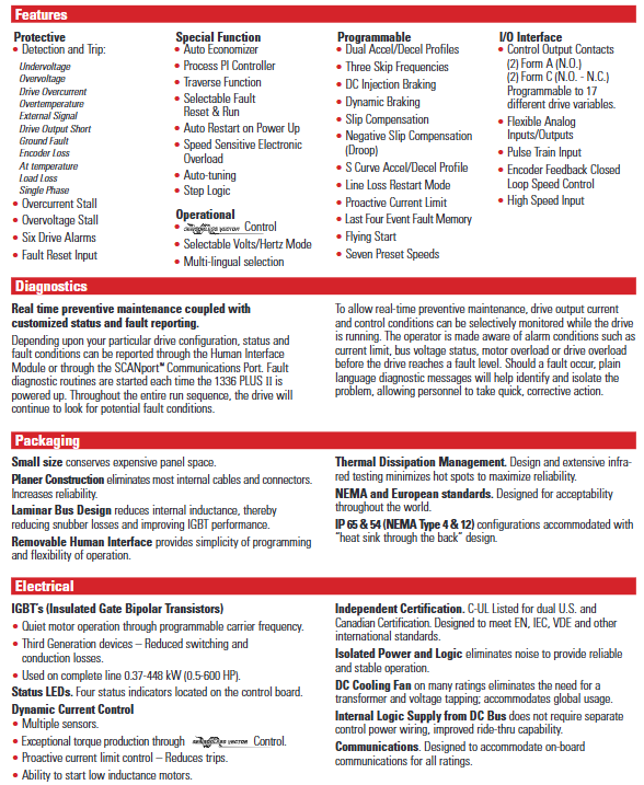
Function positioning: Based on microprocessor, PWM AC driver is used to control the speed of three-phase motors. It adapts to various load requirements through adjustable voltage/frequency (V/Hz) or sensorless vector control, especially suitable for industrial scenarios with high requirements for torque and speed accuracy (such as fans, pumps, conveyors, etc.).
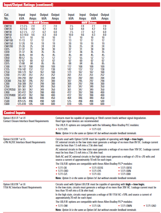
Power and voltage range: The power covers 0.37-448kW (0.5-600 horsepower) and supports three voltage levels -200-240V AC, 380-480V AC, and 500-600V AC, which can meet industrial power supply standards in different regions.
Compatibility advantage: with Allen Bradley SMC ™、 SMP ™ Power products, 1305 drivers, 1336 IMPACT ™ And 1336 FORCE ™ Vector control drivers share control interfaces and communication options to reduce system design, integration, and maintenance costs.
2. Core design highlights
Structural design: Flat construction reduces internal cables and connectors, improving reliability; Laminar busbar design reduces internal inductance, minimizes buffering losses, and optimizes IGBT performance; Removable Human Machine Interface (HIM) simplifies programming and operation.
Heat dissipation and protection: optimize thermal management through infrared testing to reduce hotspots; Supports IP20 (NEMA Type 1, Universal), IP54 (NEMA Type 12, Dustproof), IP65 (NEMA Type 4, Waterproof and Dustproof) protection levels, suitable for different industrial environments.
Global adaptation: Compliant with international standards such as UL, CSA, EN, IEC, VDE, etc., equipped with DC cooling fans, no need for transformers and voltage taps, supporting global use.

Key specification parameters
1. Electrical protection specifications
The protection threshold of drivers with different voltage levels varies, and the core protection parameters are shown in the following table:
Protection project: 200-240V driver, 380-480V driver, 500-600V driver
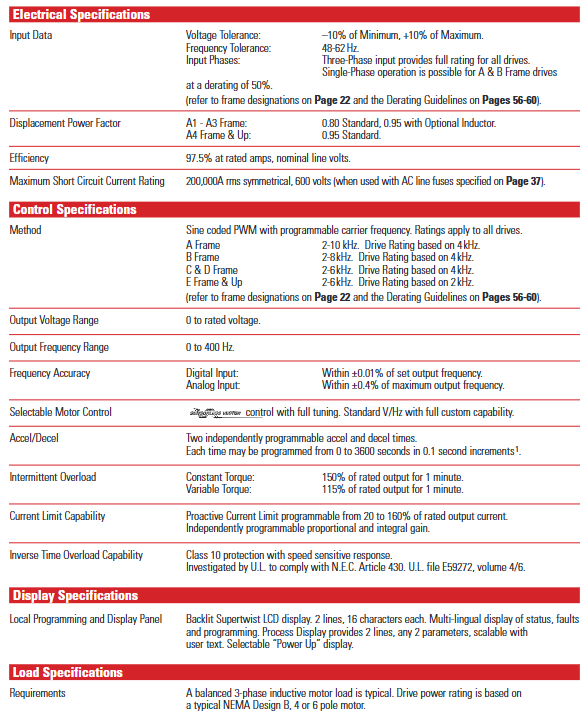
AC input overvoltage trip 285V AC 570V AC 690V AC
AC input undervoltage trip 138V AC 280V AC 343V AC
Bus overvoltage tripping 405V DC 810V DC 1013V DC
Bus undervoltage tripping 200V DC 400V DC 498V DC
Driver overcurrent trip (hardware) 180-250% rated current 180-250% rated current 180-250% rated current
Grounding fault tripping output terminal phase to phase grounding detection output terminal phase to phase grounding detection output terminal phase to phase grounding detection
In addition, the drive also has fault detection and trip protection functions such as overheating, encoder loss, load loss, and single-phase operation, and supports 6 types of drive alarm and fault reset inputs.
2. Environment and operating specifications
Environmental conditions: Maximum altitude of 1000m (without capacity reduction), exceeding this limit requires reference to the capacity reduction guidelines; The working temperature IP00 (open type) is 0-50 ℃, and IP20/54/65 is 0-40 ℃; Storage temperature -40-70 ℃; Relative humidity 5-95% (no condensation), shock resistance 15G peak (11ms), vibration resistance 0.006 inches displacement (1G peak).
Output performance: Output frequency range 0-400Hz, frequency accuracy (digital input) ± 0.01% set value, (analog input) ± 0.4% maximum value; Acceleration/deceleration time can be independently programmed (0-3600 seconds, 0.1 second increments); The overload capacity of constant torque load for 1 minute is 150% of the rated output, and the overload capacity of variable torque load for 1 minute is 115% of the rated output.
Core functional characteristics
1. Motor control function
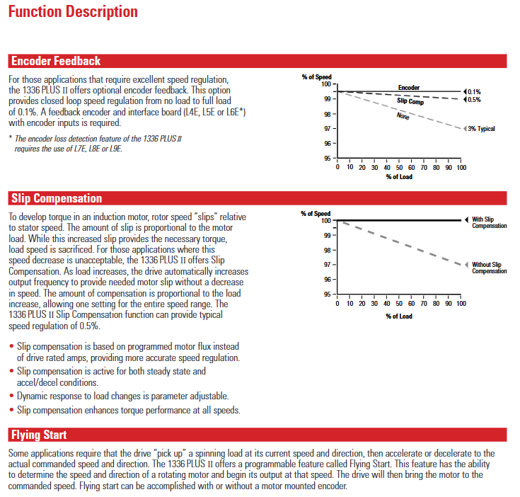
Sensorless vector control: Excellent torque performance at low speeds (as low as 15rpm), with a constant torque speed range of 120:1 and a starting/accelerating torque of up to 250%. It supports motor parameter self-tuning (requires input of motor nameplate values) and is suitable for fast acceleration requirements of low inertia loads.
V/Hz control: fully programmable mode, supporting startup lifting, operation lifting, and slope adjustment for lifting, suitable for multi motor co drive scenarios (such as different power motors sharing one driver).
Slip compensation: Automatically increase the output frequency according to the load, compensate for the rotor slip of the induction motor, with a typical speed adjustment accuracy of 0.5%, to avoid speed drop caused by increased load.
Flying Start function: It can detect the speed and direction of the rotating motor without the need for an encoder, start from the current speed and transition to the commanded speed, and adapt to scenarios such as fans and pumps that require "load start".
2. Process control and protection
Process PI controller: Through proportional (KP) and integral (KI) gain adjustment, combined with feedback scaling, error reversal, and output clamping, it achieves speed closed-loop control based on feedback signals (such as pressure and flow), supporting "automatic/manual" switching and smooth transition.
Braking function: Supports DC injection braking (programming time 0-90 seconds), dynamic braking (requires an external braking unit), and continuous holding braking (sets the "Ramp to Hold" mode, outputs the set current at zero frequency until the start command or enable is disconnected).
Power outage response: Supports two modes of "line loss fault enable/disable". When there is a line loss, the operation is maintained through DC bus energy storage. When the bus voltage drops to 85% of the rated value, the output is turned off. After power is restored, it can be restarted through methods such as flying start and detecting motor voltage.
3. Monitoring and Diagnosis
Real time monitoring: Display output current, voltage, frequency, temperature and other parameters through HIM's backlight ultra twisted LCD (2 lines x 16 characters), supporting multilingual switching; The "Process Display" mode allows customization of display units and parameter combinations (such as "121.6 In/min" and "2.7AmPs").
Fault recording and diagnosis: Cache the last 4 faults and automatically start the fault diagnosis program upon startup; When there is a malfunction, display a prompt in _plain language_ (such as "Undervolt Fault" or "Overtemp Fault") and report the status through the HIM or SCANPort communication port.
Installation and Wiring Guide
1. Installation requirements
Size and weight: There are significant differences in the size of drivers with different frames (A1-G). Taking IP20 (NEMA Type 1) as an example, A1 frame size is 215.9 × 290.0 × 160.0mm (width × height × depth), weighing 4.31kg; G frame size is 635.0 × 2324.1 × 508.3mm, weighing 453.6kg (please refer to the specific frame size table).
Installation spacing: At least 152.4mm (6 inches) of ventilation space should be reserved on both sides and the back; The F-frame drive requires additional side/back space, and when the open drive is installed in the user housing, it needs to be equipped with two 725 CFM fans (BPR series requires fans of 450 CFM or above).
2. Wiring specifications
Power wiring (TB1 terminal): input terminals R (L1), S (L2), T (L3), output terminals U (T1), V (T2), W (T3), DC bus terminal+DC/- DC, grounding terminals PE (protective ground), TE (shielding ground); 75 ℃ copper wire is required, with different wire diameters for different frame terminals (maximum 5.3mm ²/10AWG for A1-A4 frame, maximum 303.6mm ²/600MCM for G frame), and torque must comply with specifications (such as 1.81N/m/16lb in for A1-A4 frame).
Control and signal wiring:
Analog I/O: Standard configuration supports 0-10V/0-20mA input (single ended non isolated), optional LA series isolation card (such as LA2 dual isolated input, LA3 dual isolated output), shielding layer needs to be connected to TE terminal.
The digital I/O: TB3 terminal supports 115V AC/24V AC/DC/TTL level input and can be programmed with functions such as start, stop, reverse, and preset speed selection; The output contacts (CR1-CR4) support 115V AC/30V DC, 5A resistive/2A inductive loads.
Encoder wiring: Supports 5V DC/8-15V DC line driven encoder (orthogonal or pulse signal), maximum input frequency 250kHz, single ended/differential signal can be used, and the shielding layer is connected to the TE terminal.
Selection and Configuration
1. Selection Guide
Model interpretation: The complete model format is "1336F-XXXXXX-XX", such as "1336F-B020-AA", where "B" represents the voltage/power code (460V, 20HP), "020" represents the power level, and "AA" represents the protection level (IP20/NEMA Type 1).
Load adaptation: The selection of constant torque (CT) and variable torque (VT) loads needs to be distinguished, for example, the 460V B020 model, CT rated 20HP, VT rated 25HP; the corresponding model needs to be selected according to the actual load type (such as CT for conveyor belt and VT for fan).
Option configuration: Supports factory pre installation or on-site installation options, such as communication cards (GM1 single node RIO, GM5 DeviceNet), control interface cards (L4 contact closed, L5 24V AC/DC), HIM (HA1 analog potentiometer, HJ2 digital potentiometer), braking units, reactors, etc.
2. Capacity reduction guide
When the operating conditions of the drive exceed the rated range, it is necessary to reduce the capacity. The core scenarios for reducing the capacity include:
Altitude: When it exceeds 1000m, the capacity decreases by about 6% for every 1000m increase (refer to Figure AD).
When the ambient temperature exceeds 40 ℃, the capacity will decrease by about 2% for every 1 ℃ increase (refer to Figure A-AC).
Carrier frequency: When it exceeds 4kHz (some models are 2kHz), the amplitude should be increased and the capacitance should be reduced according to the frequency (such as reducing the capacitance by 10% at 6kHz).
Fault handling and maintenance
1. Common faults and troubleshooting
The document lists more than 40 types of fault codes, and the core faults and their handling methods are as follows:
Fault code, fault name, cause analysis, and handling suggestions
04 Under voltage fault: Input voltage too low, bus capacitor fault, power failure. Check input voltage, replace capacitor, and confirm power stability
05 Overvoltage fault: Input voltage too high, brake unit fault, high load regeneration energy. Check input voltage, repair brake unit, and increase regeneration resistance
07 Overload fault: Excessive motor load, motor stalling, improper overload parameter settings. Reduce load, investigate the cause of stalling, and reset the overload current
08 Overheating fault: Cooling fan failure, high ambient temperature, blocked air duct. Replace the fan, improve ventilation, and clean the air duct
13. Grounding fault output terminal short circuit to ground, motor insulation damage. Check the output circuit and test the motor insulation resistance
2. Preventive maintenance
Regular inspection: Check the operation status of the cooling fan and the cleanliness of the air duct every week; Check the tightness of wiring terminals and the insulation layer of cables every month; Quarterly testing of bus voltage and output current balance.
Maintenance records: Use HIM to view parameters such as "Elapsed Run Time" and "Motor OL Count" to predict component lifespan (such as fan lifespan of approximately 20000 hours).
- YOKOGAWA
- Reliance
- ADVANCED
- SEW
- ProSoft
- WATLOW
- Kongsberg
- FANUC
- VSD
- DCS
- PLC
- man-machine
- Covid-19
- Energy and Gender
- Energy Access
- Renewable Integration
- Energy Subsidies
- Energy and Water
- Net zero emission
- Energy Security
- Critical Minerals
- A-B
- petroleum
- Mine scale
- Sewage treatment
- cement
- architecture
- Industrial information
- New energy
- Automobile market
- electricity
- Construction site
- HIMA
- ABB
- Rockwell
- Schneider Modicon
- Siemens
- xYCOM
- Yaskawa
- Woodward
- BOSCH Rexroth
- MOOG
- General Electric
- American NI
- Rolls-Royce
- CTI
- Honeywell
- EMERSON
- MAN
- GE
- TRICONEX
- Control Wave
- ALSTOM
- AMAT
- STUDER
- KONGSBERG
- MOTOROLA
- DANAHER MOTION
- Bentley
- Galil
- EATON
- MOLEX
- Triconex
- DEIF
- B&W
- ZYGO
- Aerotech
- DANFOSS
- KOLLMORGEN
- Beijer
- Endress+Hauser
- schneider
- Foxboro
- KB
- REXROTH
- YAMAHA
- Johnson
- Westinghouse
- WAGO
- TOSHIBA
- TEKTRONIX
- BENDER
- BMCM
- SMC
- HITACHI
- HIRSCHMANN
- XP POWER
- Baldor
- Meggitt
- SHINKAWA
- Other Brands
- UniOP
- KUKA
- IBA
- Beckhoff
- ADLINK
-
Beckhoff EP9224-0037 - 4-Channel Power Distribution Box EtherCAT
-
Beckhoff CX2900-0026 - Solid State Flash Memory Card 20GB CFast
-
Beckhoff BK7500 - SERCOS Interface Fieldbus Bus Coupler Terminal
-
Beckhoff Ep2328-0002 - 4-Channel Input 4-Channel Output EtherCAT Box IP67
-
Beckhoff CX1020-0111 - Controller Kit Combo Interface Modules
-
B&R X20AI2237 - X20 System Analog Input Interface Module
-
Beckhoff CP2221-0010 - Multi-Touch Built-In Panel PC Touchscreen
-
Beckhoff CX1500-M310 - Fieldbus Master Interface Module 24V
-
Beckhoff CX2100-0904 - Power Charging Module Smart UPS Extension
-
Beckhoff CP3918-0000 - Multi-Touch Control Panel 18.5-Inch Monitor
-
Beckhoff CP6500-1012-0060 - Control Cabinet PC Interface Unit
-
Beckhoff FC5202-0000 - 2-Channel DeviceNet Master PCI Interface Card
-
Beckhoff CP6606-0001-0020 - 7-Inch Economy Panel PC Touch
-
Beckhoff CP2921-0010 - Multi-Touch Integrated Control Panel Display
-
Beckhoff CP7802-0001-0010 - 15-Inch Touch Screen Control Panel HMI
-
Beckhoff C6920-0050 - Control Cabinet Industrial PC
-
Beckhoff BK9105 - EtherNet/IP Bus Coupler Network Interface
-
Beckhoff 31 Modules - Bus Terminal Slice I/O Lot Assortment
-
Beckhoff CX2020-0120 - Embedded PC Basic CPU Module 8GB CFast Card
-
Beckhoff CP7001-0000 - HMI Control Panel Touch Screen
-
B&R 7EX484.50-1 - System 2005 Controller Base Module Slots
-
Beckhoff EK1322 - 2-Port EtherCAT P Extension Feed-In Terminal
-
Beckhoff CP6606-0001-0020 - 7-Inch Single-Touch Economy Panel PC
-
Beckhoff CP6607-0001-0000 - Economy Installation Operator Panel PC 5.7-Inch
-
Beckhoff AX5103-0000-0200 - Digital Compact Servo Driver 3 Phase
-
Beckhoff CP7802-0001-0010 - 15-Inch Touch Screen Control Panel
-
Beckhoff AX8620 - Power Supply Module Axis System
-
Beckhoff CX2030-0121 - Embedded PC Controller Module
-
Beckhoff CP6606-0001-0020 - 7-Inch Economy Panel PC Touch Screen
-
Beckhoff CX2030-0121 - Embedded PC CPU Module Windows Standard 7
-
Beckhoff BX3100-0000 - PROFIBUS DP Bus Terminal Controller
-
Beckhoff CX1020-0000 - Controller Set with Power Supply Unit
-
Beckhoff EK1100 - EtherCAT Coupler Terminal Module Set
-
Beckhoff CP7002-1043-0010 - HMI Display Panel with Control Panel Bracket
-
Beckhoff AM8031-0D10-0000 - Synchronous Servo Motor
-
Beckhoff CX5130-0175 - Embedded PC 4GB RAM Controller
-
Beckhoff CX5130-0155 - Embedded PC Automation Controller
-
Beckhoff C6930-0010 - Control Cabinet Industrial PC Core Duo
-
Beckhoff CP3924-0000 - Multi-Touch Control Panel Display
-
Beckhoff AM8023-0F20-0000 - Synchronous Servo Motor
-
B&R KL3362 - Bus Terminal Thermocouple Input Module
-
Beckhoff AL2006-0000-0000 - Linear Servo Motor Three Phase
-
Beckhoff CX5140-0155 - Embedded PC CPU Controller Module
-
Beckhoff FC9002 - Ethernet PCI Network Interface Card
-
Beckhoff CP7203-0021-0040 - Built-In Panel PC 19-Inch Touch Screen
-
Beckhoff C6930-0020 - Control Cabinet Industrial PC HDD CF Card
-
Beckhoff CX2900-0033 - Memory Card CFast Storage
-
Beckhoff CP6201-0001-0020 - Built-In Panel PC Display
-
b+m surface systems C6930-1121-0060 - Industrial PC Beckhoff Core i7
-
Beckhoff CP2221-0010 - Multi-Touch Built-In Panel PC
-
Beckhoff C6017-0010 - Ultra-Compact Industrial PC
-
Beckhoff FC5102-0000 - 2-Channel CANopen PCI Interface Card
-
Beckhoff CP7021-0000-0000 - HMI Control Panel Interface
-
Beckhoff CP2216-0020 - Multi-Touch Built-In Panel PC
-
Beckhoff C6140 - Industrial PC Tower System Pentium 4
-
Beckhoff AM3033-1E40 - Servo Motor with Gearbox Assembly
-
Beckhoff CX9020-0115 - Embedded PC CPU Controller Module
-
Beckhoff CP6809-0001-0000 - Built-In Control Panel HMI Terminal
-
Beckhoff CP3919-0000 - Multi-Touch Control Panel Touchscreen Monitor
-
Beckhoff AM8053-0LHB-0000 - Synchronous Servo Motor
-
Beckhoff C6920-1028-0000 - Control Cabinet Industrial Computer PC
-
Beckhoff CX1100-0014 - Power Supply Unit for CX1030
-
Beckhoff CX9001-0101 - Embedded PC CPU Controller Module
-
Beckhoff CP3916-1428-0000 - Control Panel Multi-Touch Monitor
-
Beckhoff CP7037-1027-0010 - HMI Built-In Control Panel PC
-
Beckhoff CX1020-0120 - CPU Module DVI USB Windows Standard
-
Beckhoff CX5020-0121 - Embedded PC Controller Module
-
Beckhoff EL5042 - 2-Channel Encoder Interface BiSS C EtherCAT Terminal
-
Beckhoff CP7201-0021-0040 - Built-In Panel PC Touch Monitor
-
B&R X20-RT-8401 - reACTION Technology Module I/O Block
-
Beckhoff CP2915-0010 - HMI Control Panel Display Touch Screen
-
Beckhoff EL7221 - Servomotor Cyber Terminal EtherCAT Module
-
Beckhoff CX5140-0175 - Embedded PC CPU Module
-
Beckhoff C6017-0010 - Ultra-Compact Industrial PC
-
Beckhoff CX2020-0130 - Embedded PC Basic CPU Module
-
Beckhoff CX1030-0011 - Basic CPU Module Windows CE 6.0
-
Beckhoff AM8043-1E00-0000 - Synchronous Servo Motor
-
Beckhoff CX1020-0110 - CPU Module Controller Interface Bundle
-
Beckhoff C6930-1069-0030 - Control Cabinet Industrial PC Mainboard CB3054-0001
-
Beckhoff KL9528 - Power Supply Terminal Module
-
Beckhoff AM8053-0K20-0000 - Synchronous Servo Motor
-
Beckhoff CX5020-1111 - Embedded PC Controller Module
-
Beckhoff CX5130-0175 - Embedded PC CPU Module Intel Atom
-
Beckhoff CP6401-1024-0040 - Husky Display Control Panel HMI Terminal
-
Beckhoff CP2616-0000 - Multi-Touch Display Automation Panel PC
-
Beckhoff CP7921-1075-0000 - 12-Inch HMI Control Panel ELO Touch
-
Beckhoff C6930-0060 - Control Cabinet Industrial PC SSD
-
Beckhoff AX5112-0000 - Digital Compact Servo Drive 3 Phase
-
Beckhoff C6930-0040 - Control Cabinet Industrial PC Intel Core i5
-
Beckhoff CP2616-0000 - Multi-Touch Display Automation Panel PC
-
Beckhoff KL1414 - 4-Channel Digital Input Bus Terminal
-
Beckhoff CX1020-0000 - Basic CPU Module Controller
-
Beckhoff CP6201-1008-0000 - 12-Inch Built-In Panel PC
-
Beckhoff CP7021-0000 - HMI Control Panel Display Screen
-
Beckhoff AX5106-0000 - Digital Compact Servo Drive
-
Beckhoff BX3100-0000 - Profibus DP Bus Terminal Controller
-
Beckhoff CP2916-0000 - Multi-Touch Built-In Control Panel
-
Beckhoff C6925-0030 - Fanless Control Cabinet Industrial PC
-
Beckhoff C6330 - Industrial PC Motherboard Boser HS6237 Celeron
-
Beckhoff AM3033-0C00-0000 - Synchronous Servo Motor
-
Beckhoff EL6080 - EtherCAT Memory Terminal Module
-
Beckhoff CX2100-0014 - Power Supply Unit Module
-
Beckhoff CP6907-1000-000 - Economy Built-In Control Panel HMI
-
Bosch CP2715-1014-0010 - Panel PC Touch Screen Monitor
-
Beckhoff C6920-0050 - Control Cabinet Industrial PC
-
Beckhoff CP2712-1002-0000 - Baumann Automation Touch Control Panel PC
-
Beckhoff CX1001-0111 - Embedded PC CPU Power Supply Fieldbus Module Assembly
-
Beckhoff AM8061-0JH1-0000 - Synchronous Servo Motor
-
Nexcom EBS1575P - System Module Beckhoff Fieldbus Interface FC3101
-
Beckhoff CU8860-1000 - USB Extended Receiver Module
-
Beckhoff C9620-1080-0040 - Control Cabinet Industrial PC
-
Beckhoff C6640-0000 - Control Cabinet Industrial PC
-
Beckhoff C6525-0030 - Fanless Built-In Industrial PC
-
Beckhoff CX2030-0121 - Embedded PC CPU Module TwinCAT 2
-
Beckhoff CX5130-0155 - Embedded PC CPU Module
-
Beckhoff CX1020-0000 - Controller Set Module Combination Set
-
Beckhoff CU2005 - Industrial Ethernet Switch Module
-
Beckhoff ELM9410-0000 - Power Supply Terminal EtherCAT
-
Beckhoff AM8023-0EH1-0000 - Synchronous Servo Motor
-
Beckhoff CX5020-0112 - Embedded PC CF Memory Card
-
Beckhoff CP3921-0010 - Control Panel Multi-Touch Screen
-
Beckhoff CP7232-1000-0000 - Industrial Panel PC Touch Screen
-
Beckhoff C6525-1022-0005 - Fanless Built-In Industrial PC
-
Beckhoff AM3052-0K41-1001 - Synchronous Servo Motor
-
Beckhoff CP2921-0010 - Multi-Touch Built-In Control Panel
-
Beckhoff c6017-0010 - Ultra-Compact Industrial PC
-
Beckhoff AX5106-0000-0200 - Servo Drive Intelligent Drive Module
-
Beckhoff BK7200 - Fipio Bus Coupler PLC Module

K-JIANG

Add: Jimei North Road, Jimei District, Xiamen, Fujian, China
Tell:+86-15305925923