
K-WANG


Allen Bradley 150 Series SMC Dialog Plus Controller
Allen Bradley 150 Series SMC Dialog Plus Controller
Core framework and scope of application
The document is divided into 10 core chapters and 4 appendices, with a clear and progressive structure based on the logic of "operation process+technical details". The applicable product is SMC Dialog Plus controller (Bulletin 150), which supports rated current of 1-1000A, voltage of 200-480V AC or 200-600V AC, and frequency of 50/60Hz. It can control three-phase squirrel cage motors and is suitable for various scenarios such as motor starting, speed regulation, braking, etc. in the industrial field, such as motor control of pumps, fans, compressors, conveyor belts and other equipment.
Core chapter content sorting
(1) Product Overview: Functions and Core Features
Startup mode: Provides 4 standard startup modes to meet different load requirements
Soft Start: The initial torque (0-90% locked rotor torque) and acceleration ramp time (0-30 seconds) can be adjusted, and the motor automatically switches to full pressure operation after reaching rated speed, suitable for general loads.
Current Limit Start: Limit the maximum starting current (50-600% of the rated motor current) for 0-30 seconds to avoid excessive starting current impacting the power grid, suitable for scenarios with limited transformer capacity.
Dual Ramp Start: Supports two independent soft start parameters (ramp time, initial torque) that can be switched and used to adapt to equipment with large load fluctuations (such as crushers and mixers).
Full Voltage Start: Output full voltage within 1/4 second, suitable for loads that require quick start-up (such as emergency backup motors).
Additional features: Optional Kickstart, providing short pulses (0.0-2.0 seconds) of 550% rated current to assist in starting high static friction loads (such as heavy-duty conveyor belts).
Protection and diagnostic functions: ensuring the safety of motors and controllers in all aspects
Overload protection: Supports overload levels of 10/15/20/30, can be manually/automatically reset, requires input of motor rated current (FLC), service factor and other parameters, monitors motor thermal utilization rate through thermal memory algorithm, and triggers protection when reaching 100%.
Fault protection: covering stalling (0.0-10.0 seconds delay), jamming (current threshold 0-999% FLC, delay 0.0-10.0 seconds), underload (0-99% FLC, delay 0-99 seconds), overvoltage/undervoltage (delay can be set based on rated voltage percentage), voltage imbalance (0-25% threshold), phase loss, SCR open circuit (shutdown after 3 failed starts), overtemperature (monitoring SCR temperature, cutting off output when exceeded), etc.
Additional features: phase balance (requires 825 converter module), energy-saving mode (reduces output voltage and losses under light load, not suitable for bypass contactor scenarios), hourly start limit (0-99 times), to avoid frequent motor overheating during startup.
Measurement and status monitoring: real-time feedback of operational data
It can monitor parameters such as three-phase voltage, three-phase current, power (kW), energy consumption (kWh), power factor (displacement power factor), motor thermal utilization rate, and operating time. Some functions (such as current measurement) require the use of an 825 converter module during bypass operation.
Control options: 6 optional functions, expanding the application scenarios of the controller
Soft Stop: The voltage ramp drops for 0-60 seconds, extending the load shutdown time and avoiding water hammer effects in pump equipment.
Pump Control: The start (0-30 seconds) and stop (0-120 seconds) times can be set to smoothly accelerate/decelerate and reduce pipeline pressure fluctuations.
Preset Slow Speed: Provides low-speed Jog function with forward 7%/15% and reverse 10%/20% rated speed, used for equipment positioning or debugging, and cannot operate for a long time (due to insufficient motor heat dissipation).
Intelligent Motor Braking (SMB): No additional equipment is required, apply a braking current of 0-400% FLC, automatically cut off at zero speed, and shorten downtime (such as elevators and centrifuges).
Accu Stop: Combining SMB braking with preset low speed, brake to low speed before stopping, suitable for scenarios that require precise positioning (such as packaging machines).
Slow Speed with Braking: Braking can be triggered after low-speed braking, balancing debugging and safe shutdown.
(2) Installation: Environment and hardware requirements
Reception and Storage
Before opening the box, it is necessary to check that the product model is consistent with the order and confirm that there is no transportation damage; Long term storage should meet the requirements of temperature -20 ° C~+75 ° C, humidity 0% -95% (no condensation), and avoid corrosive environments.
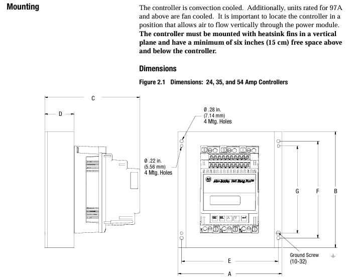
Heat dissipation and casing
The controller is of an open design and needs to be installed inside a metal casing. The temperature inside the casing should be maintained between 0 ° C and 50 ° C. The heat dissipation power of controllers with different current levels varies (such as 110W for 24A and 2760W for 1000A), and sufficient ventilation openings should be reserved in the ventilation casing (such as 65cm ² openings for 24-54A). Some models (97A and above) come with their own cooling fans, and the fan power supply needs to be wired separately.
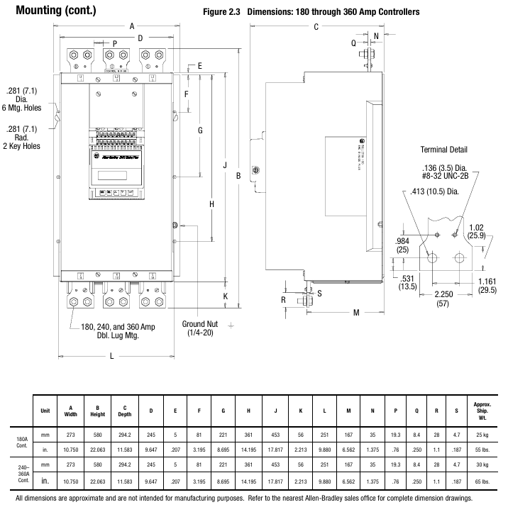
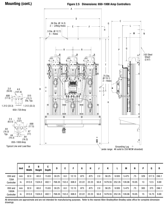
Installation specifications
The radiator fins need to be installed vertically, with at least 15cm of space reserved above and below to ensure air circulation; Grounding should be connected to the controller's dedicated grounding screw/terminal post, in accordance with the IEC 5019 grounding identification standard.
(3) Wiring: Power and Control Circuit Configuration
Power wiring
The input (L1/L2/L3) is connected to the power grid, and the output (T1/T2/T3) is connected to the motor. Different current levels of terminals are compatible with different wire specifications (such as 24-54A supporting 2.5-25mm ² wires, 1000A supporting 50-240mm ² wires), and the terminals need to be tightened according to the torque specified in the manual (such as 0.8N · m for 2.5-6mm ² wires).
Suggest installing a fast current limiting fuse (such as 24A with 170M 3610-63) to protect the SCR from overcurrent damage; The power factor correction capacitor needs to be installed on the input side of the controller to avoid damage to the SCR caused by capacitor discharge.
Control wiring
The control power supply supports 100-240V AC (± 15%/± 10%) or 24V AC/DC (± 15%/± 10%), and requires separate connection to terminals 11/12. The control module has a power consumption of 40VA, and the cooling fan requires additional power supply (such as 45VA for 97A fans).
Control terminal functions: terminals 13 (enable), 16 (start), 17 (stop), 19-20 (auxiliary contacts 1&2, Form C, can be set to "normal/rated speed"), 29-30 (auxiliary contact 3, can be set to "normal/fault"), some terminals (such as 25-28) are used to connect converter modules or communication modules.
Typical wiring scheme: Provides 12 scenario wiring diagrams, including standard control, dual ramp start, bypass operation, reverse control, manual automatic (SCANPort) control, etc. If the bypass configuration requires the use of an 825 converter module to maintain current monitoring and avoid loss of protection function after controller bypass.
(4) Programming: Parameter Setting and Operation
Programming interface: Operated through the built-in 2-line 16 character backlit LCD and 4 keys (ESC/SEL/up and down arrows), the menu is divided into 4 levels (operation layer → mode layer → group layer → parameter layer), supports password protection (prevents unauthorized modification) and "search" mode (only displays non default parameters).
Core parameter group
Basic Setup: Configure startup mode, ramp time, current limit, energy-saving mode, auxiliary contact function, etc., suitable for fast startup.
Advanced Setup: includes dual ramp parameters, overvoltage/undervoltage thresholds, voltage imbalance protection, phase balance, hourly startup times, etc., suitable for complex scenarios.
Calibrate: Input the motor nameplate data (rated current, service factor, motor code, etc.), and use a true RMS clamp meter (accuracy ± 1%) to calibrate the current measurement and ensure the accuracy of the protection function.
Parameter storage: Parameters are stored in RAM by default (lost during power failure) and need to be manually saved to EEPROM (non-volatile). It supports restoring factory default values.
(5) Diagnosis and Troubleshooting: Problem Localization and Resolution
Fault display: The first row of the LCD displays the fault type (such as "OVERLOAD"), the second row displays the fault code (such as "F7"), and the fault buffer stores the last 5 fault records.
Common faults and solutions
Overload (F7): Check if the motor load is too large, if the overload level matches the motor, and if the FLC parameters are entered correctly.
Phase loss (F1-F3): Check if the power grid incoming line and motor wiring are loose, and if the fuse is blown.
SCR open circuit (F23-F25): Measure the resistance between the incoming and outgoing lines of the power module (normally>10k Ω). If there is a short circuit, replace the power module.
Communication Failure (F21): Check if the human-machine interface or communication module connected to SCANPort is disconnected, and if the Logic Mask parameter is set to 4 (enabling communication control).
Maintenance operation: When disassembling the control module, power off first, mark the wires, and then loosen the fixing screws to avoid bending the interface pins; The resistance inspection of the power module requires the use of an ohmmeter to measure the feedback resistance, gate resistance, and thermistor. If they do not meet the standards, the module needs to be replaced.
(6) Serial Communication: Remote Control and Data Interaction
Communication interface: SCANPort is standard and can be connected to 1201 human-machine interface module (programming, start stop control) or 1203 communication module (supporting protocols such as Remote I/O, DeviceNet, DH-485, etc.).
Control Enable: Parameter 85 (Logic Mask) needs to be set to 4 to enable remote control; PLC can send start stop, fault reset, option commands (such as pump stop), receive controller status (running, fault, rated speed) and metering data (current, power).
Communication example: Provide ladder diagram program examples for controllers such as SLC 500 and PLC 5, such as implementing block transfer (BTW/BTR) through Remote I/O, reading motor current, power and other parameters, or performing explicit message transmission through DeviceNet (such as reading fault codes).
Appendix and Supplementary Resources
Appendix A (Specifications): Detailed list of electrical parameters (such as insulation voltage, impulse voltage, dielectric loss tolerance), environmental parameters (altitude 2000 meters, humidity 5% -95%), and measurement accuracy (voltage ± 2%, current ± 5%).
Appendix B (Parameter Table): Summarize the numbers, units, ranges, and default values of all 88 parameters. For example, parameter 30 (Ramp Time # 1) defaults to 10 seconds and ranges from 0 to 30 seconds.
Appendix C (Replacement of Parts): Provide control module, power module SCR、 Models of spare parts such as cooling fans (such as the 24-54A standard control module 40888-490-01-S1FX).
Appendix D (Accessories): Includes accessory models and uses such as protection modules (e.g. 150-N84 for 24-54A 480V systems), terminal lugs, communication cables, converter modules (825-MCM20 compatible with 1-12.5A motors), etc.
Key precautions
Safety regulations: Installation and maintenance require power-off operation to avoid contact with live parts; Emergency stop needs to be configured separately, and functions such as soft stop and SMB braking cannot replace emergency stop, in compliance with NFPA 70E and other standards.
Selection and adaptation: Select the controller model and functional options based on the rated current of the motor, load type (such as pump control options), and starting mode requirements to avoid overload or insufficient functionality.
Calibration requirements: Motor data (FLC, service factor) must be accurately inputted, and current calibration must be performed when the motor is loaded at 70% or more to ensure protection function and measurement accuracy.
- YOKOGAWA
- Reliance
- ADVANCED
- SEW
- ProSoft
- WATLOW
- Kongsberg
- FANUC
- VSD
- DCS
- PLC
- man-machine
- Covid-19
- Energy and Gender
- Energy Access
- Renewable Integration
- Energy Subsidies
- Energy and Water
- Net zero emission
- Energy Security
- Critical Minerals
- A-B
- petroleum
- Mine scale
- Sewage treatment
- cement
- architecture
- Industrial information
- New energy
- Automobile market
- electricity
- Construction site
- HIMA
- ABB
- Rockwell
- Schneider Modicon
- Siemens
- xYCOM
- Yaskawa
- Woodward
- BOSCH Rexroth
- MOOG
- General Electric
- American NI
- Rolls-Royce
- CTI
- Honeywell
- EMERSON
- MAN
- GE
- TRICONEX
- Control Wave
- ALSTOM
- AMAT
- STUDER
- KONGSBERG
- MOTOROLA
- DANAHER MOTION
- Bentley
- Galil
- EATON
- MOLEX
- Triconex
- DEIF
- B&W
- ZYGO
- Aerotech
- DANFOSS
- KOLLMORGEN
- Beijer
- Endress+Hauser
- schneider
- Foxboro
- KB
- REXROTH
- YAMAHA
- Johnson
- Westinghouse
- WAGO
- TOSHIBA
- TEKTRONIX
- BENDER
- BMCM
- SMC
- HITACHI
- HIRSCHMANN
- XP POWER
- Baldor
- Meggitt
- SHINKAWA
- Other Brands
- UniOP
- KUKA
- IBA
- Beckhoff
- ADLINK
-
Beckhoff EP9224-0037 - 4-Channel Power Distribution Box EtherCAT
-
Beckhoff CX2900-0026 - Solid State Flash Memory Card 20GB CFast
-
Beckhoff BK7500 - SERCOS Interface Fieldbus Bus Coupler Terminal
-
Beckhoff Ep2328-0002 - 4-Channel Input 4-Channel Output EtherCAT Box IP67
-
Beckhoff CX1020-0111 - Controller Kit Combo Interface Modules
-
B&R X20AI2237 - X20 System Analog Input Interface Module
-
Beckhoff CP2221-0010 - Multi-Touch Built-In Panel PC Touchscreen
-
Beckhoff CX1500-M310 - Fieldbus Master Interface Module 24V
-
Beckhoff CX2100-0904 - Power Charging Module Smart UPS Extension
-
Beckhoff CP3918-0000 - Multi-Touch Control Panel 18.5-Inch Monitor
-
Beckhoff CP6500-1012-0060 - Control Cabinet PC Interface Unit
-
Beckhoff FC5202-0000 - 2-Channel DeviceNet Master PCI Interface Card
-
Beckhoff CP6606-0001-0020 - 7-Inch Economy Panel PC Touch
-
Beckhoff CP2921-0010 - Multi-Touch Integrated Control Panel Display
-
Beckhoff CP7802-0001-0010 - 15-Inch Touch Screen Control Panel HMI
-
Beckhoff C6920-0050 - Control Cabinet Industrial PC
-
Beckhoff BK9105 - EtherNet/IP Bus Coupler Network Interface
-
Beckhoff 31 Modules - Bus Terminal Slice I/O Lot Assortment
-
Beckhoff CX2020-0120 - Embedded PC Basic CPU Module 8GB CFast Card
-
Beckhoff CP7001-0000 - HMI Control Panel Touch Screen
-
B&R 7EX484.50-1 - System 2005 Controller Base Module Slots
-
Beckhoff EK1322 - 2-Port EtherCAT P Extension Feed-In Terminal
-
Beckhoff CP6606-0001-0020 - 7-Inch Single-Touch Economy Panel PC
-
Beckhoff CP6607-0001-0000 - Economy Installation Operator Panel PC 5.7-Inch
-
Beckhoff AX5103-0000-0200 - Digital Compact Servo Driver 3 Phase
-
Beckhoff CP7802-0001-0010 - 15-Inch Touch Screen Control Panel
-
Beckhoff AX8620 - Power Supply Module Axis System
-
Beckhoff CX2030-0121 - Embedded PC Controller Module
-
Beckhoff CP6606-0001-0020 - 7-Inch Economy Panel PC Touch Screen
-
Beckhoff CX2030-0121 - Embedded PC CPU Module Windows Standard 7
-
Beckhoff BX3100-0000 - PROFIBUS DP Bus Terminal Controller
-
Beckhoff CX1020-0000 - Controller Set with Power Supply Unit
-
Beckhoff EK1100 - EtherCAT Coupler Terminal Module Set
-
Beckhoff CP7002-1043-0010 - HMI Display Panel with Control Panel Bracket
-
Beckhoff AM8031-0D10-0000 - Synchronous Servo Motor
-
Beckhoff CX5130-0175 - Embedded PC 4GB RAM Controller
-
Beckhoff CX5130-0155 - Embedded PC Automation Controller
-
Beckhoff C6930-0010 - Control Cabinet Industrial PC Core Duo
-
Beckhoff CP3924-0000 - Multi-Touch Control Panel Display
-
Beckhoff AM8023-0F20-0000 - Synchronous Servo Motor
-
B&R KL3362 - Bus Terminal Thermocouple Input Module
-
Beckhoff AL2006-0000-0000 - Linear Servo Motor Three Phase
-
Beckhoff CX5140-0155 - Embedded PC CPU Controller Module
-
Beckhoff FC9002 - Ethernet PCI Network Interface Card
-
Beckhoff CP7203-0021-0040 - Built-In Panel PC 19-Inch Touch Screen
-
Beckhoff C6930-0020 - Control Cabinet Industrial PC HDD CF Card
-
Beckhoff CX2900-0033 - Memory Card CFast Storage
-
Beckhoff CP6201-0001-0020 - Built-In Panel PC Display
-
b+m surface systems C6930-1121-0060 - Industrial PC Beckhoff Core i7
-
Beckhoff CP2221-0010 - Multi-Touch Built-In Panel PC
-
Beckhoff C6017-0010 - Ultra-Compact Industrial PC
-
Beckhoff FC5102-0000 - 2-Channel CANopen PCI Interface Card
-
Beckhoff CP7021-0000-0000 - HMI Control Panel Interface
-
Beckhoff CP2216-0020 - Multi-Touch Built-In Panel PC
-
Beckhoff C6140 - Industrial PC Tower System Pentium 4
-
Beckhoff AM3033-1E40 - Servo Motor with Gearbox Assembly
-
Beckhoff CX9020-0115 - Embedded PC CPU Controller Module
-
Beckhoff CP6809-0001-0000 - Built-In Control Panel HMI Terminal
-
Beckhoff CP3919-0000 - Multi-Touch Control Panel Touchscreen Monitor
-
Beckhoff AM8053-0LHB-0000 - Synchronous Servo Motor
-
Beckhoff C6920-1028-0000 - Control Cabinet Industrial Computer PC
-
Beckhoff CX1100-0014 - Power Supply Unit for CX1030
-
Beckhoff CX9001-0101 - Embedded PC CPU Controller Module
-
Beckhoff CP3916-1428-0000 - Control Panel Multi-Touch Monitor
-
Beckhoff CP7037-1027-0010 - HMI Built-In Control Panel PC
-
Beckhoff CX1020-0120 - CPU Module DVI USB Windows Standard
-
Beckhoff CX5020-0121 - Embedded PC Controller Module
-
Beckhoff EL5042 - 2-Channel Encoder Interface BiSS C EtherCAT Terminal
-
Beckhoff CP7201-0021-0040 - Built-In Panel PC Touch Monitor
-
B&R X20-RT-8401 - reACTION Technology Module I/O Block
-
Beckhoff CP2915-0010 - HMI Control Panel Display Touch Screen
-
Beckhoff EL7221 - Servomotor Cyber Terminal EtherCAT Module
-
Beckhoff CX5140-0175 - Embedded PC CPU Module
-
Beckhoff C6017-0010 - Ultra-Compact Industrial PC
-
Beckhoff CX2020-0130 - Embedded PC Basic CPU Module
-
Beckhoff CX1030-0011 - Basic CPU Module Windows CE 6.0
-
Beckhoff AM8043-1E00-0000 - Synchronous Servo Motor
-
Beckhoff CX1020-0110 - CPU Module Controller Interface Bundle
-
Beckhoff C6930-1069-0030 - Control Cabinet Industrial PC Mainboard CB3054-0001
-
Beckhoff KL9528 - Power Supply Terminal Module
-
Beckhoff AM8053-0K20-0000 - Synchronous Servo Motor
-
Beckhoff CX5020-1111 - Embedded PC Controller Module
-
Beckhoff CX5130-0175 - Embedded PC CPU Module Intel Atom
-
Beckhoff CP6401-1024-0040 - Husky Display Control Panel HMI Terminal
-
Beckhoff CP2616-0000 - Multi-Touch Display Automation Panel PC
-
Beckhoff CP7921-1075-0000 - 12-Inch HMI Control Panel ELO Touch
-
Beckhoff C6930-0060 - Control Cabinet Industrial PC SSD
-
Beckhoff AX5112-0000 - Digital Compact Servo Drive 3 Phase
-
Beckhoff C6930-0040 - Control Cabinet Industrial PC Intel Core i5
-
Beckhoff CP2616-0000 - Multi-Touch Display Automation Panel PC
-
Beckhoff KL1414 - 4-Channel Digital Input Bus Terminal
-
Beckhoff CX1020-0000 - Basic CPU Module Controller
-
Beckhoff CP6201-1008-0000 - 12-Inch Built-In Panel PC
-
Beckhoff CP7021-0000 - HMI Control Panel Display Screen
-
Beckhoff AX5106-0000 - Digital Compact Servo Drive
-
Beckhoff BX3100-0000 - Profibus DP Bus Terminal Controller
-
Beckhoff CP2916-0000 - Multi-Touch Built-In Control Panel
-
Beckhoff C6925-0030 - Fanless Control Cabinet Industrial PC
-
Beckhoff C6330 - Industrial PC Motherboard Boser HS6237 Celeron
-
Beckhoff AM3033-0C00-0000 - Synchronous Servo Motor
-
Beckhoff EL6080 - EtherCAT Memory Terminal Module
-
Beckhoff CX2100-0014 - Power Supply Unit Module
-
Beckhoff CP6907-1000-000 - Economy Built-In Control Panel HMI
-
Bosch CP2715-1014-0010 - Panel PC Touch Screen Monitor
-
Beckhoff C6920-0050 - Control Cabinet Industrial PC
-
Beckhoff CP2712-1002-0000 - Baumann Automation Touch Control Panel PC
-
Beckhoff CX1001-0111 - Embedded PC CPU Power Supply Fieldbus Module Assembly
-
Beckhoff AM8061-0JH1-0000 - Synchronous Servo Motor
-
Nexcom EBS1575P - System Module Beckhoff Fieldbus Interface FC3101
-
Beckhoff CU8860-1000 - USB Extended Receiver Module
-
Beckhoff C9620-1080-0040 - Control Cabinet Industrial PC
-
Beckhoff C6640-0000 - Control Cabinet Industrial PC
-
Beckhoff C6525-0030 - Fanless Built-In Industrial PC
-
Beckhoff CX2030-0121 - Embedded PC CPU Module TwinCAT 2
-
Beckhoff CX5130-0155 - Embedded PC CPU Module
-
Beckhoff CX1020-0000 - Controller Set Module Combination Set
-
Beckhoff CU2005 - Industrial Ethernet Switch Module
-
Beckhoff ELM9410-0000 - Power Supply Terminal EtherCAT
-
Beckhoff AM8023-0EH1-0000 - Synchronous Servo Motor
-
Beckhoff CX5020-0112 - Embedded PC CF Memory Card
-
Beckhoff CP3921-0010 - Control Panel Multi-Touch Screen
-
Beckhoff CP7232-1000-0000 - Industrial Panel PC Touch Screen
-
Beckhoff C6525-1022-0005 - Fanless Built-In Industrial PC
-
Beckhoff AM3052-0K41-1001 - Synchronous Servo Motor
-
Beckhoff CP2921-0010 - Multi-Touch Built-In Control Panel
-
Beckhoff c6017-0010 - Ultra-Compact Industrial PC
-
Beckhoff AX5106-0000-0200 - Servo Drive Intelligent Drive Module
-
Beckhoff BK7200 - Fipio Bus Coupler PLC Module

K-JIANG

Add: Jimei North Road, Jimei District, Xiamen, Fujian, China
Tell:+86-15305925923