
K-WANG


Allen Bradley 1734 series POINT I/O common terminal module and voltage terminal module
Common Terminal Module (1734-CTM/CTMK): Used to expand the common terminal wiring capability of POINT I/O modules, supporting centralized management of common lines for 8-channel high-density I/O modules. The suffix "K" is the conformal coating version (moisture-proof/corrosive environment), with specifications consistent with the uncoated version.
Allen Bradley 1734 series POINT I/O common terminal module and voltage terminal module
Core framework and scope of application
The document follows the logical mainline of "safety regulations → installation process → wiring guidance → technical parameters", covering the entire process of module preparation to deployment. The applicable products are two types of terminal modules in the 1734 series:
Common Terminal Module (1734-CTM/CTMK): Used to expand the common terminal wiring capability of POINT I/O modules, supporting centralized management of common lines for 8-channel high-density I/O modules. The suffix "K" is the conformal coating version (moisture-proof/corrosive environment), with specifications consistent with the uncoated version.
Voltage Terminal Module (1734-VTM/VTMK): Provides voltage output terminals to distribute power to field devices such as sensors and actuators, and also supports 8-channel configuration. The "K" version is a conformal coating version.
Applicable scenarios: In industrial automation control systems, it is used in conjunction with 1734 series POINT I/O modules (such as digital input/output modules, analog modules) to solve terminal expansion and power distribution problems in high-density wiring scenarios. It is compatible with 1734-TB/TBS (two-piece terminal base) and 1734-TOP/TOPS (one-piece terminal base), but not compatible with 1734-TB3/TB3S and 1734-TOP3/TOP3S bases.
Core content sorting
(1) Preparation in advance: Safety regulations and environmental requirements
Safety prerequisite
Operation qualification: Installation, wiring, and maintenance must be carried out by trained professionals and comply with local electrical regulations (such as NFPA 70E, EN/IEC standards).
Static electricity protection: The module is sensitive to static electricity. When operating, it is necessary to touch a grounded object to discharge and wear a grounding wristband. It is forbidden to touch the pins or components of the circuit board. When idle, it should be stored in anti-static packaging.
Attention to hazardous environments: If used in Class I, Zone 2 hazardous areas, it must be installed in a compliant enclosure and the wiring method must meet local explosion-proof standards; When replacing modules or terminals, power off or ensure that the environment is not hazardous.
Environmental and shell requirements
Environmental level: Suitable for industrial environments with pollution level 2, overvoltage category II (EN/IEC 60664-1), altitude up to 2000 meters (no need to downgrade), prohibited for residential environments.
Shell requirements: The module is of open design and needs to be installed inside a closed shell. The shell should have flame retardant properties (flame propagation level 5VA or non-metallic materials need to be certified), and the interior can only be accessed through tools. The protection level should refer to NEMA 250 or EN/IEC 60529 standards (such as dustproof and waterproof requirements).
Temperature range: Operating temperature -20 ° C~+55 ° C (-4 ° F~+131 ° F), non operating temperature -40 ° C~+85 ° C (-40 ° F~+185 ° F). Exceeding this range can cause module failure.
(2) Installation process: Base, module, and terminal block deployment
1. Install the terminal base (Mounting Base)
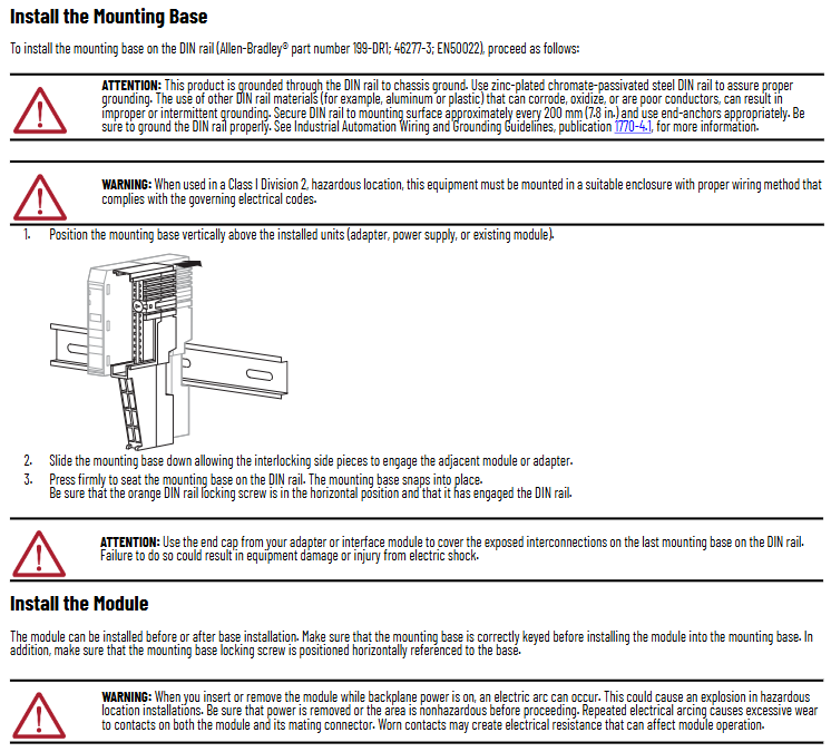
The module needs to be installed on a DIN rail through a 1734-TB/TBS or 1734-TOP/TOPS terminal base (recommended Allen Bradley 199-DR1 rail, compliant with EN 50022 standard). The steps are as follows:
Rail grounding confirmation: Use galvanized chromate passivated steel rails (aluminum/plastic rails are prone to oxidation or poor conductivity, which can cause grounding abnormalities), fix the rails every 200mm (7.8 inches), and install end anchors at both ends. Grounding must comply with the Industrial Automation Wiring and Grounding Guidelines (1770-4.1).
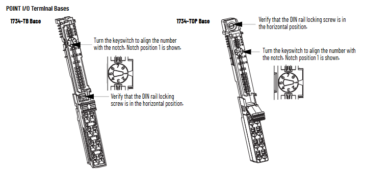
Positioning and installation of the base: Align the base vertically with the installed equipment (adapter, power supply, or existing module), slide down to engage the side interlocking structure with adjacent equipment, and press until the buckle is locked; Confirm that the orange DIN rail locking screw is in a horizontal position (unlocked) to prevent the base from loosening.
End cap protection: The end cap of the terminal base should be covered with an adapter or interface module to prevent electric shock or equipment damage to the exposed interconnected parts.
2. Install terminal module
The module can be deployed before or after installation on the base, and the key steps are as follows:
Base key switch configuration: Use a Phillips screwdriver to rotate the orange key switch on the base clockwise to align the corresponding module type number with the base groove (default position 1, refer to the module label for details), ensuring correct mechanical positioning.
Module installation: Insert the module vertically into the base and press it until the locking buckle is engaged; If the base is powered on, inserting/removing the module may generate an arc. In hazardous environments, power should be cut off first to avoid explosions caused by the arc.
3. Install Removable Terminal Block (RTB)
Module matching 1734-RTB (detachable terminal block), supports wire free replacement of base, installation steps:
Terminal block positioning: Insert the RTB handleless end (with arc-shaped buckle) into the base and rotate it to lock (hear a "click" sound).
Handle fixation: If the I/O module has been installed, fasten the RTB handle onto the module to ensure that the terminal block is stable; When disassembling, simply pull the handle upwards without removing the wiring.
Special terminal block operation:
1734-RTBS/RTB3S: Use a 3mm diameter screwdriver (1492-N90) to insert into the opening at a 73 ° angle and gently push up to lock/unlock the wiring.
1734-TOPS/TOP3S: Insert the screwdriver into the opening at a 97 ° angle to avoid damaging the terminals.
(3) Wiring guidance: Terminal definition and typical scenarios
The module needs to be used in conjunction with POINT I/O modules, and the wiring needs to be disconnected first. The key specifications are as follows:
1. Terminal definition
1734-CTM (Common Terminal Module): The terminals are divided into "Common 0-7", corresponding to the common end of the 8-channel I/O module (such as the power common line of the digital module), which centrally manages the common line and reduces wiring redundancy.
1734-VTM (Voltage Terminal Module): The terminals are divided into "Voltage out 0~7" (voltage output) and "Common 0~7" (common terminal), providing power distribution for on-site equipment. The output voltage needs to be matched with an external power source (10~28.8V DC or 120/240V AC).
2. Typical wiring scenarios
The document provides wiring diagrams for four core scenarios (Figures 4 to 7), with key examples as follows:
Leakage type input wiring (1734-IB8 module+CTM/VTM): The "signal terminal" of the 2-wire/3-wire proximity sensor is connected to the input terminal of the I/O module, the "power terminal" is connected to the "Voltage out" of the VTM, and the "common terminal" is connected to the "Common" of the CTM, achieving separate management of power and common terminals.
Source type output wiring (1734-OB8 module+CTM): The "positive pole" of the actuator (such as indicator lights, relays) is connected to the output terminal of the I/O module, and the "negative pole" is centrally connected to the "Common" of the CTM, simplifying multi device common terminal wiring.
Universal wiring (adapter+CTM/VTM): VTM connects to an external power source to distribute voltage to other devices; CTM connects to the adapter's common end, achieving the aggregation of multiple module common lines and avoiding duplicate wiring.
3. Wiring parameters
Wire specifications: Supports solid or stranded copper wire of 0.25~2.5mm ² (22~14 AWG), with a maximum insulation thickness of 1.2mm (3/64 inches), and a rated temperature of ≥ 75 ° C (167 ° F).
Terminal torque: The tightening torque of the base screw is 0.8 N · m (7 lb · in), excessive tightening can damage the terminal.
(4) Technical parameters: Electrical and environmental specifications
1. General parameters
Parameter values
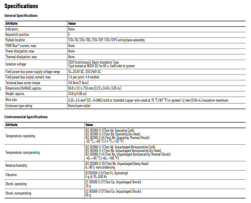
No indicator light
Key switch position 5
Adaptation base 1734-TB/TBS, 1734-TOP/TOPS
POINT Bus maximum current none
Maximum power consumption/heat dissipation none (only terminal expansion, no active components)
Isolation voltage 250V AC (continuous), 1600V DC (60 second test, on-site system side)
On site power bus voltage 10~28.8V DC, 120/240V AC
The maximum output current of the on-site power bus is 2A per point and 4A per module
The dimensions (height x width x depth) are approximately 56.6 x 12.1 x 77.5mm (2.23 x 0.48 x 3.05 inches)
Weight approximately 30.9g (1.09 ounces)
2. Environmental parameters
Parameter standards and numerical values
Working temperature -20 ° C~+55 ° C (-4 ° F~+131 ° F), in accordance with IEC 60068-2-1/2/14
Non working temperature -40 ° C~+85 ° C (-40 ° F~+185 ° F), in accordance with IEC 60068-2-1/2/14
Relative humidity of 5%~95% (non condensing), in accordance with IEC 60068-2-30
Vibration (working) 5g @ 10~500Hz, in accordance with IEC 60068-2-6
Impact (working) 30g, compliant with IEC 60068-2-27
50g impact (non working), in accordance with IEC 60068-2-27
3. Authentication information
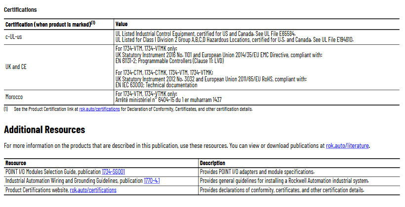
C-UL-US certification: UL listed industrial control equipment, suitable for the United States and Canada; Certification for Class I Zone 2 (Groups A/B/C/D) Hazardous Areas (UL Document E194810).
UK and CE certification: VTM/VTMK complies with UK Regulation 1101 of 2016 and EU EMC Directive 2014/35/EU (EN 61131-2); All modules comply with the EU 2011/65/EU RoHS Directive (EN IEC 63000).
Moroccan certification: VTM/VTMK complies with Moroccan Ministerial Decree No. 6404-15.
(5) Module dismantling and maintenance
Dismantling process: The module, adjacent module on the right side, and RTB (if wired) need to be dismantled first. The steps are:
Disconnect the RTB handle buckle and pull out the RTB;
Press the lock button on the top of the module and pull out the module;
Use a Phillips screwdriver to rotate the orange base locking screw to a vertical position, release the locking mechanism, and lift the base upwards to complete the removal.
Maintenance precautions: Do not disassemble the module by yourself in case of a malfunction and return it to the manufacturer for repair; When cleaning, only dry anti-static cloth can be used for wiping, and the use of cleaning agents is prohibited.
- YOKOGAWA
- Reliance
- ADVANCED
- SEW
- ProSoft
- WATLOW
- Kongsberg
- FANUC
- VSD
- DCS
- PLC
- man-machine
- Covid-19
- Energy and Gender
- Energy Access
- Renewable Integration
- Energy Subsidies
- Energy and Water
- Net zero emission
- Energy Security
- Critical Minerals
- A-B
- petroleum
- Mine scale
- Sewage treatment
- cement
- architecture
- Industrial information
- New energy
- Automobile market
- electricity
- Construction site
- HIMA
- ABB
- Rockwell
- Schneider Modicon
- Siemens
- xYCOM
- Yaskawa
- Woodward
- BOSCH Rexroth
- MOOG
- General Electric
- American NI
- Rolls-Royce
- CTI
- Honeywell
- EMERSON
- MAN
- GE
- TRICONEX
- Control Wave
- ALSTOM
- AMAT
- STUDER
- KONGSBERG
- MOTOROLA
- DANAHER MOTION
- Bentley
- Galil
- EATON
- MOLEX
- Triconex
- DEIF
- B&W
- ZYGO
- Aerotech
- DANFOSS
- KOLLMORGEN
- Beijer
- Endress+Hauser
- schneider
- Foxboro
- KB
- REXROTH
- YAMAHA
- Johnson
- Westinghouse
- WAGO
- TOSHIBA
- TEKTRONIX
- BENDER
- BMCM
- SMC
- HITACHI
- HIRSCHMANN
- XP POWER
- Baldor
- Meggitt
- SHINKAWA
- Other Brands
- UniOP
- KUKA
- IBA
- Beckhoff
- ADLINK
-
Beckhoff CP6500-1012-0060 - Control Cabinet PC Interface Unit
-
Beckhoff FC5202-0000 - 2-Channel DeviceNet Master PCI Interface Card
-
Beckhoff CP6606-0001-0020 - 7-Inch Economy Panel PC Touch
-
Beckhoff CP2921-0010 - Multi-Touch Integrated Control Panel Display
-
Beckhoff CP7802-0001-0010 - 15-Inch Touch Screen Control Panel HMI
-
Beckhoff C6920-0050 - Control Cabinet Industrial PC
-
Beckhoff BK9105 - EtherNet/IP Bus Coupler Network Interface
-
Beckhoff 31 Modules - Bus Terminal Slice I/O Lot Assortment
-
Beckhoff CX2020-0120 - Embedded PC Basic CPU Module 8GB CFast Card
-
Beckhoff CP7001-0000 - HMI Control Panel Touch Screen
-
B&R 7EX484.50-1 - System 2005 Controller Base Module Slots
-
Beckhoff EK1322 - 2-Port EtherCAT P Extension Feed-In Terminal
-
Beckhoff CP6606-0001-0020 - 7-Inch Single-Touch Economy Panel PC
-
Beckhoff CP6607-0001-0000 - Economy Installation Operator Panel PC 5.7-Inch
-
Beckhoff AX5103-0000-0200 - Digital Compact Servo Driver 3 Phase
-
Beckhoff CP7802-0001-0010 - 15-Inch Touch Screen Control Panel
-
Beckhoff AX8620 - Power Supply Module Axis System
-
Beckhoff CX2030-0121 - Embedded PC Controller Module
-
Beckhoff CP6606-0001-0020 - 7-Inch Economy Panel PC Touch Screen
-
Beckhoff CX2030-0121 - Embedded PC CPU Module Windows Standard 7
-
Beckhoff BX3100-0000 - PROFIBUS DP Bus Terminal Controller
-
Beckhoff CX1020-0000 - Controller Set with Power Supply Unit
-
Beckhoff EK1100 - EtherCAT Coupler Terminal Module Set
-
Beckhoff CP7002-1043-0010 - HMI Display Panel with Control Panel Bracket
-
Beckhoff AM8031-0D10-0000 - Synchronous Servo Motor
-
Beckhoff CX5130-0175 - Embedded PC 4GB RAM Controller
-
Beckhoff CX5130-0155 - Embedded PC Automation Controller
-
Beckhoff C6930-0010 - Control Cabinet Industrial PC Core Duo
-
Beckhoff CP3924-0000 - Multi-Touch Control Panel Display
-
Beckhoff AM8023-0F20-0000 - Synchronous Servo Motor
-
B&R KL3362 - Bus Terminal Thermocouple Input Module
-
Beckhoff AL2006-0000-0000 - Linear Servo Motor Three Phase
-
Beckhoff CX5140-0155 - Embedded PC CPU Controller Module
-
Beckhoff FC9002 - Ethernet PCI Network Interface Card
-
Beckhoff CP7203-0021-0040 - Built-In Panel PC 19-Inch Touch Screen
-
Beckhoff C6930-0020 - Control Cabinet Industrial PC HDD CF Card
-
Beckhoff CX2900-0033 - Memory Card CFast Storage
-
Beckhoff CP6201-0001-0020 - Built-In Panel PC Display
-
b+m surface systems C6930-1121-0060 - Industrial PC Beckhoff Core i7
-
Beckhoff CP2221-0010 - Multi-Touch Built-In Panel PC
-
Beckhoff C6017-0010 - Ultra-Compact Industrial PC
-
Beckhoff FC5102-0000 - 2-Channel CANopen PCI Interface Card
-
Beckhoff CP7021-0000-0000 - HMI Control Panel Interface
-
Beckhoff CP2216-0020 - Multi-Touch Built-In Panel PC
-
Beckhoff C6140 - Industrial PC Tower System Pentium 4
-
Beckhoff AM3033-1E40 - Servo Motor with Gearbox Assembly
-
Beckhoff CX9020-0115 - Embedded PC CPU Controller Module
-
Beckhoff CP6809-0001-0000 - Built-In Control Panel HMI Terminal
-
Beckhoff CP3919-0000 - Multi-Touch Control Panel Touchscreen Monitor
-
Beckhoff AM8053-0LHB-0000 - Synchronous Servo Motor
-
Beckhoff C6920-1028-0000 - Control Cabinet Industrial Computer PC
-
Beckhoff CX1100-0014 - Power Supply Unit for CX1030
-
Beckhoff CX9001-0101 - Embedded PC CPU Controller Module
-
Beckhoff CP3916-1428-0000 - Control Panel Multi-Touch Monitor
-
Beckhoff CP7037-1027-0010 - HMI Built-In Control Panel PC
-
Beckhoff CX1020-0120 - CPU Module DVI USB Windows Standard
-
Beckhoff CX5020-0121 - Embedded PC Controller Module
-
Beckhoff EL5042 - 2-Channel Encoder Interface BiSS C EtherCAT Terminal
-
Beckhoff CP7201-0021-0040 - Built-In Panel PC Touch Monitor
-
B&R X20-RT-8401 - reACTION Technology Module I/O Block
-
Beckhoff CP2915-0010 - HMI Control Panel Display Touch Screen
-
Beckhoff EL7221 - Servomotor Cyber Terminal EtherCAT Module
-
Beckhoff CX5140-0175 - Embedded PC CPU Module
-
Beckhoff C6017-0010 - Ultra-Compact Industrial PC
-
Beckhoff CX2020-0130 - Embedded PC Basic CPU Module
-
Beckhoff CX1030-0011 - Basic CPU Module Windows CE 6.0
-
Beckhoff AM8043-1E00-0000 - Synchronous Servo Motor
-
Beckhoff CX1020-0110 - CPU Module Controller Interface Bundle
-
Beckhoff C6930-1069-0030 - Control Cabinet Industrial PC Mainboard CB3054-0001
-
Beckhoff KL9528 - Power Supply Terminal Module
-
Beckhoff AM8053-0K20-0000 - Synchronous Servo Motor
-
Beckhoff CX5020-1111 - Embedded PC Controller Module
-
Beckhoff CX5130-0175 - Embedded PC CPU Module Intel Atom
-
Beckhoff CP6401-1024-0040 - Husky Display Control Panel HMI Terminal
-
Beckhoff CP2616-0000 - Multi-Touch Display Automation Panel PC
-
Beckhoff CP7921-1075-0000 - 12-Inch HMI Control Panel ELO Touch
-
Beckhoff C6930-0060 - Control Cabinet Industrial PC SSD
-
Beckhoff AX5112-0000 - Digital Compact Servo Drive 3 Phase
-
Beckhoff C6930-0040 - Control Cabinet Industrial PC Intel Core i5
-
Beckhoff CP2616-0000 - Multi-Touch Display Automation Panel PC
-
Beckhoff KL1414 - 4-Channel Digital Input Bus Terminal
-
Beckhoff CX1020-0000 - Basic CPU Module Controller
-
Beckhoff CP6201-1008-0000 - 12-Inch Built-In Panel PC
-
Beckhoff CP7021-0000 - HMI Control Panel Display Screen
-
Beckhoff AX5106-0000 - Digital Compact Servo Drive
-
Beckhoff BX3100-0000 - Profibus DP Bus Terminal Controller
-
Beckhoff CP2916-0000 - Multi-Touch Built-In Control Panel
-
Beckhoff C6925-0030 - Fanless Control Cabinet Industrial PC
-
Beckhoff C6330 - Industrial PC Motherboard Boser HS6237 Celeron
-
Beckhoff AM3033-0C00-0000 - Synchronous Servo Motor
-
Beckhoff EL6080 - EtherCAT Memory Terminal Module
-
Beckhoff CX2100-0014 - Power Supply Unit Module
-
Beckhoff CP6907-1000-000 - Economy Built-In Control Panel HMI
-
Bosch CP2715-1014-0010 - Panel PC Touch Screen Monitor
-
Beckhoff C6920-0050 - Control Cabinet Industrial PC
-
Beckhoff CP2712-1002-0000 - Baumann Automation Touch Control Panel PC
-
Beckhoff CX1001-0111 - Embedded PC CPU Power Supply Fieldbus Module Assembly
-
Beckhoff AM8061-0JH1-0000 - Synchronous Servo Motor
-
Nexcom EBS1575P - System Module Beckhoff Fieldbus Interface FC3101
-
Beckhoff CU8860-1000 - USB Extended Receiver Module
-
Beckhoff C9620-1080-0040 - Control Cabinet Industrial PC
-
Beckhoff C6640-0000 - Control Cabinet Industrial PC
-
Beckhoff C6525-0030 - Fanless Built-In Industrial PC
-
Beckhoff CX2030-0121 - Embedded PC CPU Module TwinCAT 2
-
Beckhoff CX5130-0155 - Embedded PC CPU Module
-
Beckhoff CX1020-0000 - Controller Set Module Combination Set
-
Beckhoff CU2005 - Industrial Ethernet Switch Module
-
Beckhoff ELM9410-0000 - Power Supply Terminal EtherCAT
-
Beckhoff AM8023-0EH1-0000 - Synchronous Servo Motor
-
Beckhoff CX5020-0112 - Embedded PC CF Memory Card
-
Beckhoff CP3921-0010 - Control Panel Multi-Touch Screen
-
Beckhoff CP7232-1000-0000 - Industrial Panel PC Touch Screen
-
Beckhoff C6525-1022-0005 - Fanless Built-In Industrial PC
-
Beckhoff AM3052-0K41-1001 - Synchronous Servo Motor
-
Beckhoff CP2921-0010 - Multi-Touch Built-In Control Panel
-
Beckhoff c6017-0010 - Ultra-Compact Industrial PC
-
Beckhoff AX5106-0000-0200 - Servo Drive Intelligent Drive Module
-
Beckhoff BK7200 - Fipio Bus Coupler PLC Module
-
Beckhoff EP-M845B - Industrial Mainboard Motherboard Rev 2.1
-
Beckhoff CX5020-0111 - Embedded PC CPU Module
-
Beckhoff CP6802-0001-0010 - Built-In HMI Control Panel
-
Beckhoff CX2100-0004 - Power Supply Unit Module
-
Beckhoff C6320 - Control Cabinet Industrial PC
-
Beckhoff C6525-0030 - Fanless Built-In Industrial PC Celeron
-
Beckhoff CX1010-0112 - Embedded PC Controller Module
-
Beckhoff EPP6002-0002 - EtherCAT Box Serial Interface
-
Beckhoff CP7721-1084-0020 - Touch Panel PC Trumpf Laser Screen
-
Beckhoff C6140 - Industrial PC Mainboard Tower Computer

K-JIANG

Add: Jimei North Road, Jimei District, Xiamen, Fujian, China
Tell:+86-15305925923