
K-WANG


Allen Bradley 1753 Series GuardPLC 1800 Controller
Allen Bradley 1753 Series GuardPLC 1800 Controller
Core framework and scope of application of the document
The document follows the logical mainline of "security standards → hardware awareness → installation and practical operation → functional verification", covering the entire process of controller preparation to later testing. The applicable product is GuardPLC 1800 safety controller, which is a programmable electronic system (PES) with safety certification. It integrates 24 digital inputs, 8 digital outputs, 2 high-speed counters, 8 analog inputs, and 4 GuardPLC Ethernet communication interfaces. It complies with SIL 3 (IEC 61508) and PLe (ISO 13849-1 Cat.4) safety levels and is suitable for scenarios with extremely high requirements for fault tolerance and risk control, such as mechanical safety control and process safety monitoring.

Core content sorting
(1) Controller Overview and Safety Standards
Core functions and hardware composition
Function integration: Supports the separation of secure and non secure communication. Secure communication is connected to distributed I/O, other GuardPLC controllers, or OPC servers through 4-channel 10/100BaseT RJ45 interfaces (GuardPLC Ethernet protocol); Non secure communication is achieved through 3-channel 9-pin D-shell interfaces (RS-485, etc.) to realize functions such as Modbus slave and Profibus DP slave (only 1753-L32BBBP-8A).
Hardware structure: including DIN rail installation buckle, 24V DC power interface, I/O plug-in terminal, high-speed counter interface, Ethernet interface (top 2+bottom 2), reset button (received design, anti misoperation), status indicator lights (24V DC, RUN, ERROR, PROMess, etc.). The controller is of open design and needs to be installed in a closed enclosure (protection level ≥ IP20).
Safety and Environmental Regulations
Operation qualification: It must be operated by trained professionals who are familiar with the application requirements of safety related PES (such as EN ISO 13849-1, IEC 61508).
Static electricity protection: The controller is sensitive to static electricity. When operating, it is necessary to touch a grounded object to discharge and wear a grounding wristband. It is forbidden to touch the pins or components of the circuit board. When idle, it should be stored in anti-static packaging.
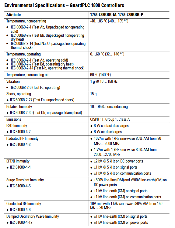
Environmental requirements:
Working temperature: 0 ° C~60 ° C (32 ° F~140 ° F), storage temperature: -40 ° C~85 ° C (-40 ° F~185 ° F);
Relative humidity of 10%~95% (no condensation), pollution level 2 industrial environment, altitude ≤ 2000 meters (no need to downgrade);
It needs to be installed inside a metal casing with flame retardant properties (flame propagation level 5VA/V0, etc.), and the interior can only be accessed through tools to avoid the risk of electric shock.
(2) Installation process: from fixing to grounding
DIN rail installation (only supports DIN rail, not panel installation)
Align the guide rail: Hang the top slot of the controller on the IEC standard DIN rail (such as 199-DR1), and it is recommended to use galvanized yellow chromium steel material for the guide rail (to ensure good grounding). Fix it every 200mm (7.8 inches) and install end anchors.
Locking device: Insert a flathead screwdriver into the gap between the housing and the buckle, pull the buckle downwards, push the controller towards the guide rail, and release the buckle to complete the locking process; Reverse the operation during disassembly.
Heat dissipation requirements: Install horizontally with a minimum gap of 100mm (3.94 inches) above and below, avoiding installation above heating equipment to ensure air circulation. Install a fan if necessary.
Grounding configuration
Double grounding: The controller is functionally grounded through DIN rail, and protective grounding must be connected through a dedicated grounding screw (with grounding symbol) in the upper left corner of the housing. The grounding wire must comply with local electrical regulations (refer to Industrial Automation Wiring and Grounding Guidelines 1770-4.1).
Guide rail requirements: It is prohibited to use guide rails made of aluminum, plastic, or other materials that are prone to corrosion or have poor conductivity, in order to avoid equipment failure or safety risks caused by poor grounding.
(3) Wiring Specification: Power Supply and I/O Circuit
Power wiring (24V DC)
Power requirements: An isolated power supply that complies with EN 60950/UL 1950 must be used, and it must be of the SELV (Safety Extra Low Voltage) or PELV (Protection Extra Low Voltage) level. The SELV voltage should be ≤ 30V rms/42.4V peak/60V DC, and the PELV must be connected to a protective grounding.
Wiring details: Connect the power supply through a 4-pin terminal, and ensure that L+(positive pole) and L - (negative pole) are correctly connected (without reverse polarity protection, as reversing the connection may damage the controller); The terminal supports a maximum of 2.5mm ² (14 AWG) wire and requires external 10A delay fuse protection; The L+and L - terminals are internally connected, and 24V DC Daisy chain power can be supplied to other devices through the remaining terminals.
Current characteristics: The maximum current consumption of the controller is 9A (including I/O load), and it requires 1A for its own operation. The remaining 8A can be used to power input/output devices.
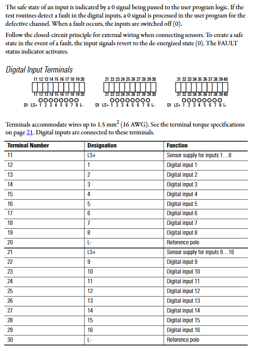
Digital input wiring (24 channels, divided into 3 groups, with 8 channels per group)
Power supply and circuit: Each set of inputs is powered by an independent LS+(24V DC sensor power supply with short-circuit protection), and the input signal is referenced to L - (common terminal); Supports dry contact input or sensors with independent power supply (such as safety light curtains), and the negative pole of the external power supply needs to be connected to the controller L.
Safety design: Following the "closed circuit principle", the input signal is reset to "0" by default in case of a fault (power-off safety state); If an input fault (such as a short circuit) is detected, the input signal of the fault channel is forced to be "0", and the FAILT indicator light is activated.
Terminal specifications: The terminal supports 0.13-1.3mm ² (26-16 AWG) wires, with a tightening torque of 0.51N · m (4.5 lb · in). Terminals 11-20, 21-30, and 31-40 correspond to three sets of input LS+, input channel, and L-。
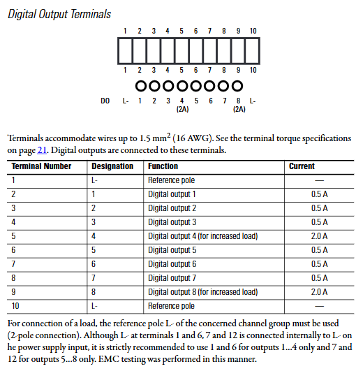
Digital output wiring (8 channels)
Load capacity:
At channels 1-3 and 5-7, the maximum current per channel is 0.5A at 60 ° C;
Channels 4 and 8 (heavy-duty channels): 1A/channel at 60 ° C, 2A/channel at 50 ° C;
The total output current is ≤ 7A, with a minimum load of 2mA per channel. When overcurrent occurs, the output is turned off and automatically restored after troubleshooting.
Wiring requirements: The output circuit should use L - (terminal 1/10) of the corresponding group as the common terminal. Even if L - is internally connected, it is still recommended to use it according to the group (EMC test verification configuration); It is recommended to parallel 1N4004 diodes to suppress interference voltage for inductive loads.
Safety feature: In the event of a fault, all outputs are forced to shut down (in a power-off safety state), and there is no monitoring of the external circuit. However, a short circuit will trigger a fault indication.
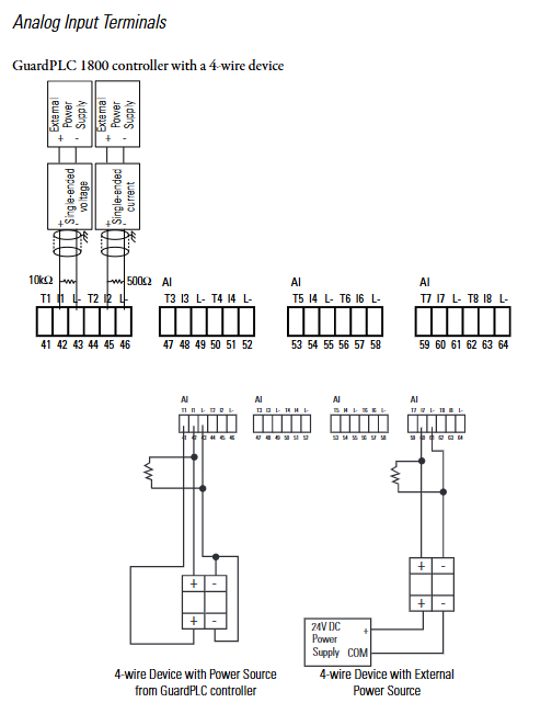
Analog input wiring (8 channels, single polarity)
Signal type:
Voltage signal: 0~10V DC (requires an external 10k Ω shunt resistor);
Current signal: 0~20mA (requires an external 500 Ω shunt resistor);
Unused analog inputs need to be short circuited (connected to I and L -) to avoid interference.
Wiring specifications: Use shielded twisted pair cables, with both ends of the shielding layer grounded, and a maximum wiring length of 300m (984 feet); Terminals 41-64 correspond to transmitter power supply (T1-T8), signal input (I1-I8), and reference terminal (L -) with 8 inputs, supporting 0.13-1.3mm ² (26-16 AWG) wires.
High speed counter wiring (2 channels, 24 bits)
Function configuration: Each counter includes three terminals: A (counting input), B (direction input), and Z (reset input). It supports 5V/24V DC signals and has a maximum input frequency of 100kHz. It can be used as a counter or a 3-digit Gray code decoder.
Wiring requirements: Use shielded twisted pair cables, with both ends of the shielding layer grounded, and a maximum wiring length of 500m (1640 feet); Terminals 65-72 correspond to A1/B1/Z1/L - and A2/B2/Z2/L - of the 2-channel counter, and unused inputs do not need to be terminated.
(4) Communication connection: Separation of secure and non secure
Secure Communication (GuardPLC Ethernet)
Interface configuration: 4 RJ45 interfaces (top 2+bottom 2), connected internally through an Ethernet switch, supporting automatic negotiation (full/half duplex, 10/100Mbps), can use direct or crossover Ethernet cables, supporting star/line topology (network loops are prohibited).
Application scenario: Connect distributed security I/O, other GuardPLC controllers, OPC servers (requiring 1753-OPC modules) and programming software, with MAC address attached to the bottom RJ45 interface.
Non secure communication (3-channel 9-pin D-shell interface)
Interface function:
COMM1:RS-485, Supports Modbus slave (1753-L32BBBM-8A) or Profibus DP slave (1753-L32BBBP-8A);
COMM2: Reserved (TBD);
COMM3:RS-485, Support GuardPLC ASCII protocol;
Pin definitions: Pin 3 (RxD/TxD-A) and Pin 8 (RxD/TxD-B) are for data transmission and reception, Pin 5 (DGND) is for data ground, Pin 6 (VP) is for 5V power supply, and Pin 4/9 are for control signals.
Default parameters: IP address defaults to 192.168.0.99, system ID (SRS) defaults to 60000, and custom parameters can be recorded through transparent labels (note not to obstruct ventilation holes).
(5) Fault diagnosis and status indication
Reset button operation
Trigger scenario: When forgetting the online password for programming software and unable to obtain IP address/SRS, use an insulated needle to press the reset button (top received hole, 4-5cm from the left edge).
Reset process: Press and hold the button for 20 seconds, while restarting the controller (power off and then on). After resetting, only the default account is retained, and the IP address/SRS is restored to its default value; Restore the parameters modified before or after resetting during the next power on (depending on whether they have been modified).
Controller self-test
Power monitoring: Alarm 1 is triggered when the 24V DC voltage is below 19.3V (recording internal variables), alarm 2 is triggered when the voltage is below 15.4V (preparing to shut down), and automatic shutdown is triggered when the voltage is below 13.0V.
Temperature monitoring: A warning is triggered when the temperature is between 60 ° C and 70 ° C, a main alarm is triggered when the temperature is above 70 ° C, and the main alarm is released when the temperature drops to 64 ° C and 54 ° C (the warning is retained). When the temperature drops below 54 ° C, it returns to normal.
Interpretation of status indicator lights
|Indicator light | Status | Meaning|
|24V DC | Always on | 24V DC power supply is normal|
|| Off | No power supply or power failure|
|RUN | Always on | Running normally (executing programs, processing I/O, communication, self-test)|
|| Blinking | STOP mode (no program executed, output reset, triggered by emergency stop)|
|| OFF | VNet STOP mode (see ERROR light)|
|ERROR | Always on | Hardware failure (controller, I/O, counter), system software error, watchdog timeout (out of cycle), software restart required|
|| Off | No errors|
|PROGress | Always on | Uploading new controller configuration|
|| Blinking | Upload new operating system to non-volatile ROM|
|FAULT | Always on | Program logic error, configuration failure, operating system damage|
|| Flashing | ROM write error, I/O failure|
|OSL | Blinking | Emergency Operating System Loader Activation|
|BL | Blinking | Boot loader unable to load operating system|
|Ethernet (green/yellow) | Green constant light | Full duplex; Huang Changliang: Connection establishment|
|| Green flashing | Conflict; Yellow flashing: Interface activity|
(6) Technical specifications and certification
Core parameters
Memory: Maximum 250KB user program memory, 250KB application data memory;
Safety performance: minimum watchdog time of 10ms, minimum safety time of 20ms;
Insulation voltage: 50V DC (basic insulation) between I/O and Ethernet, Ethernet and DC power supply;
Protection level: IP20 (controller body), size 257 × 114 × 66mm (width × height × depth), weight 1.2kg.
Safety certifications: UL Listed (USA&Canada), CE (EMC Directive 2004/108/EC), C-Tick (Australia), T Ü V certification (SIL 3/IEC 61508, PLe/ISO 13849-1).
Key considerations and supplementary resources
Compliance verification: Wiring must comply with local electrical regulations (such as NEC, IEC), and safety circuit design must meet corresponding safety level requirements to avoid reducing safety performance due to improper configuration.
EMC protection: Shielded wires are required for analog inputs, high-speed counters, and Ethernet, with both ends of the shielding layer grounded; Install a filter in the power circuit to reduce the impact of electromagnetic interference on safety functions.
- YOKOGAWA
- Reliance
- ADVANCED
- SEW
- ProSoft
- WATLOW
- Kongsberg
- FANUC
- VSD
- DCS
- PLC
- man-machine
- Covid-19
- Energy and Gender
- Energy Access
- Renewable Integration
- Energy Subsidies
- Energy and Water
- Net zero emission
- Energy Security
- Critical Minerals
- A-B
- petroleum
- Mine scale
- Sewage treatment
- cement
- architecture
- Industrial information
- New energy
- Automobile market
- electricity
- Construction site
- HIMA
- ABB
- Rockwell
- Schneider Modicon
- Siemens
- xYCOM
- Yaskawa
- Woodward
- BOSCH Rexroth
- MOOG
- General Electric
- American NI
- Rolls-Royce
- CTI
- Honeywell
- EMERSON
- MAN
- GE
- TRICONEX
- Control Wave
- ALSTOM
- AMAT
- STUDER
- KONGSBERG
- MOTOROLA
- DANAHER MOTION
- Bentley
- Galil
- EATON
- MOLEX
- Triconex
- DEIF
- B&W
- ZYGO
- Aerotech
- DANFOSS
- KOLLMORGEN
- Beijer
- Endress+Hauser
- schneider
- Foxboro
- KB
- REXROTH
- YAMAHA
- Johnson
- Westinghouse
- WAGO
- TOSHIBA
- TEKTRONIX
- BENDER
- BMCM
- SMC
- HITACHI
- HIRSCHMANN
- XP POWER
- Baldor
- Meggitt
- SHINKAWA
- Other Brands
- UniOP
- KUKA
- IBA
- Beckhoff
- ADLINK
-
Beckhoff CP6500-1012-0060 - Control Cabinet PC Interface Unit
-
Beckhoff FC5202-0000 - 2-Channel DeviceNet Master PCI Interface Card
-
Beckhoff CP6606-0001-0020 - 7-Inch Economy Panel PC Touch
-
Beckhoff CP2921-0010 - Multi-Touch Integrated Control Panel Display
-
Beckhoff CP7802-0001-0010 - 15-Inch Touch Screen Control Panel HMI
-
Beckhoff C6920-0050 - Control Cabinet Industrial PC
-
Beckhoff BK9105 - EtherNet/IP Bus Coupler Network Interface
-
Beckhoff 31 Modules - Bus Terminal Slice I/O Lot Assortment
-
Beckhoff CX2020-0120 - Embedded PC Basic CPU Module 8GB CFast Card
-
Beckhoff CP7001-0000 - HMI Control Panel Touch Screen
-
B&R 7EX484.50-1 - System 2005 Controller Base Module Slots
-
Beckhoff EK1322 - 2-Port EtherCAT P Extension Feed-In Terminal
-
Beckhoff CP6606-0001-0020 - 7-Inch Single-Touch Economy Panel PC
-
Beckhoff CP6607-0001-0000 - Economy Installation Operator Panel PC 5.7-Inch
-
Beckhoff AX5103-0000-0200 - Digital Compact Servo Driver 3 Phase
-
Beckhoff CP7802-0001-0010 - 15-Inch Touch Screen Control Panel
-
Beckhoff AX8620 - Power Supply Module Axis System
-
Beckhoff CX2030-0121 - Embedded PC Controller Module
-
Beckhoff CP6606-0001-0020 - 7-Inch Economy Panel PC Touch Screen
-
Beckhoff CX2030-0121 - Embedded PC CPU Module Windows Standard 7
-
Beckhoff BX3100-0000 - PROFIBUS DP Bus Terminal Controller
-
Beckhoff CX1020-0000 - Controller Set with Power Supply Unit
-
Beckhoff EK1100 - EtherCAT Coupler Terminal Module Set
-
Beckhoff CP7002-1043-0010 - HMI Display Panel with Control Panel Bracket
-
Beckhoff AM8031-0D10-0000 - Synchronous Servo Motor
-
Beckhoff CX5130-0175 - Embedded PC 4GB RAM Controller
-
Beckhoff CX5130-0155 - Embedded PC Automation Controller
-
Beckhoff C6930-0010 - Control Cabinet Industrial PC Core Duo
-
Beckhoff CP3924-0000 - Multi-Touch Control Panel Display
-
Beckhoff AM8023-0F20-0000 - Synchronous Servo Motor
-
B&R KL3362 - Bus Terminal Thermocouple Input Module
-
Beckhoff AL2006-0000-0000 - Linear Servo Motor Three Phase
-
Beckhoff CX5140-0155 - Embedded PC CPU Controller Module
-
Beckhoff FC9002 - Ethernet PCI Network Interface Card
-
Beckhoff CP7203-0021-0040 - Built-In Panel PC 19-Inch Touch Screen
-
Beckhoff C6930-0020 - Control Cabinet Industrial PC HDD CF Card
-
Beckhoff CX2900-0033 - Memory Card CFast Storage
-
Beckhoff CP6201-0001-0020 - Built-In Panel PC Display
-
b+m surface systems C6930-1121-0060 - Industrial PC Beckhoff Core i7
-
Beckhoff CP2221-0010 - Multi-Touch Built-In Panel PC
-
Beckhoff C6017-0010 - Ultra-Compact Industrial PC
-
Beckhoff FC5102-0000 - 2-Channel CANopen PCI Interface Card
-
Beckhoff CP7021-0000-0000 - HMI Control Panel Interface
-
Beckhoff CP2216-0020 - Multi-Touch Built-In Panel PC
-
Beckhoff C6140 - Industrial PC Tower System Pentium 4
-
Beckhoff AM3033-1E40 - Servo Motor with Gearbox Assembly
-
Beckhoff CX9020-0115 - Embedded PC CPU Controller Module
-
Beckhoff CP6809-0001-0000 - Built-In Control Panel HMI Terminal
-
Beckhoff CP3919-0000 - Multi-Touch Control Panel Touchscreen Monitor
-
Beckhoff AM8053-0LHB-0000 - Synchronous Servo Motor
-
Beckhoff C6920-1028-0000 - Control Cabinet Industrial Computer PC
-
Beckhoff CX1100-0014 - Power Supply Unit for CX1030
-
Beckhoff CX9001-0101 - Embedded PC CPU Controller Module
-
Beckhoff CP3916-1428-0000 - Control Panel Multi-Touch Monitor
-
Beckhoff CP7037-1027-0010 - HMI Built-In Control Panel PC
-
Beckhoff CX1020-0120 - CPU Module DVI USB Windows Standard
-
Beckhoff CX5020-0121 - Embedded PC Controller Module
-
Beckhoff EL5042 - 2-Channel Encoder Interface BiSS C EtherCAT Terminal
-
Beckhoff CP7201-0021-0040 - Built-In Panel PC Touch Monitor
-
B&R X20-RT-8401 - reACTION Technology Module I/O Block
-
Beckhoff CP2915-0010 - HMI Control Panel Display Touch Screen
-
Beckhoff EL7221 - Servomotor Cyber Terminal EtherCAT Module
-
Beckhoff CX5140-0175 - Embedded PC CPU Module
-
Beckhoff C6017-0010 - Ultra-Compact Industrial PC
-
Beckhoff CX2020-0130 - Embedded PC Basic CPU Module
-
Beckhoff CX1030-0011 - Basic CPU Module Windows CE 6.0
-
Beckhoff AM8043-1E00-0000 - Synchronous Servo Motor
-
Beckhoff CX1020-0110 - CPU Module Controller Interface Bundle
-
Beckhoff C6930-1069-0030 - Control Cabinet Industrial PC Mainboard CB3054-0001
-
Beckhoff KL9528 - Power Supply Terminal Module
-
Beckhoff AM8053-0K20-0000 - Synchronous Servo Motor
-
Beckhoff CX5020-1111 - Embedded PC Controller Module
-
Beckhoff CX5130-0175 - Embedded PC CPU Module Intel Atom
-
Beckhoff CP6401-1024-0040 - Husky Display Control Panel HMI Terminal
-
Beckhoff CP2616-0000 - Multi-Touch Display Automation Panel PC
-
Beckhoff CP7921-1075-0000 - 12-Inch HMI Control Panel ELO Touch
-
Beckhoff C6930-0060 - Control Cabinet Industrial PC SSD
-
Beckhoff AX5112-0000 - Digital Compact Servo Drive 3 Phase
-
Beckhoff C6930-0040 - Control Cabinet Industrial PC Intel Core i5
-
Beckhoff CP2616-0000 - Multi-Touch Display Automation Panel PC
-
Beckhoff KL1414 - 4-Channel Digital Input Bus Terminal
-
Beckhoff CX1020-0000 - Basic CPU Module Controller
-
Beckhoff CP6201-1008-0000 - 12-Inch Built-In Panel PC
-
Beckhoff CP7021-0000 - HMI Control Panel Display Screen
-
Beckhoff AX5106-0000 - Digital Compact Servo Drive
-
Beckhoff BX3100-0000 - Profibus DP Bus Terminal Controller
-
Beckhoff CP2916-0000 - Multi-Touch Built-In Control Panel
-
Beckhoff C6925-0030 - Fanless Control Cabinet Industrial PC
-
Beckhoff C6330 - Industrial PC Motherboard Boser HS6237 Celeron
-
Beckhoff AM3033-0C00-0000 - Synchronous Servo Motor
-
Beckhoff EL6080 - EtherCAT Memory Terminal Module
-
Beckhoff CX2100-0014 - Power Supply Unit Module
-
Beckhoff CP6907-1000-000 - Economy Built-In Control Panel HMI
-
Bosch CP2715-1014-0010 - Panel PC Touch Screen Monitor
-
Beckhoff C6920-0050 - Control Cabinet Industrial PC
-
Beckhoff CP2712-1002-0000 - Baumann Automation Touch Control Panel PC
-
Beckhoff CX1001-0111 - Embedded PC CPU Power Supply Fieldbus Module Assembly
-
Beckhoff AM8061-0JH1-0000 - Synchronous Servo Motor
-
Nexcom EBS1575P - System Module Beckhoff Fieldbus Interface FC3101
-
Beckhoff CU8860-1000 - USB Extended Receiver Module
-
Beckhoff C9620-1080-0040 - Control Cabinet Industrial PC
-
Beckhoff C6640-0000 - Control Cabinet Industrial PC
-
Beckhoff C6525-0030 - Fanless Built-In Industrial PC
-
Beckhoff CX2030-0121 - Embedded PC CPU Module TwinCAT 2
-
Beckhoff CX5130-0155 - Embedded PC CPU Module
-
Beckhoff CX1020-0000 - Controller Set Module Combination Set
-
Beckhoff CU2005 - Industrial Ethernet Switch Module
-
Beckhoff ELM9410-0000 - Power Supply Terminal EtherCAT
-
Beckhoff AM8023-0EH1-0000 - Synchronous Servo Motor
-
Beckhoff CX5020-0112 - Embedded PC CF Memory Card
-
Beckhoff CP3921-0010 - Control Panel Multi-Touch Screen
-
Beckhoff CP7232-1000-0000 - Industrial Panel PC Touch Screen
-
Beckhoff C6525-1022-0005 - Fanless Built-In Industrial PC
-
Beckhoff AM3052-0K41-1001 - Synchronous Servo Motor
-
Beckhoff CP2921-0010 - Multi-Touch Built-In Control Panel
-
Beckhoff c6017-0010 - Ultra-Compact Industrial PC
-
Beckhoff AX5106-0000-0200 - Servo Drive Intelligent Drive Module
-
Beckhoff BK7200 - Fipio Bus Coupler PLC Module
-
Beckhoff EP-M845B - Industrial Mainboard Motherboard Rev 2.1
-
Beckhoff CX5020-0111 - Embedded PC CPU Module
-
Beckhoff CP6802-0001-0010 - Built-In HMI Control Panel
-
Beckhoff CX2100-0004 - Power Supply Unit Module
-
Beckhoff C6320 - Control Cabinet Industrial PC
-
Beckhoff C6525-0030 - Fanless Built-In Industrial PC Celeron
-
Beckhoff CX1010-0112 - Embedded PC Controller Module
-
Beckhoff EPP6002-0002 - EtherCAT Box Serial Interface
-
Beckhoff CP7721-1084-0020 - Touch Panel PC Trumpf Laser Screen
-
Beckhoff C6140 - Industrial PC Mainboard Tower Computer

K-JIANG

Add: Jimei North Road, Jimei District, Xiamen, Fujian, China
Tell:+86-15305925923