
K-WANG


Rockwell Automation 1794 Series FLEX I/O Digital Input Module
Rockwell Automation 1794 Series FLEX I/O Digital Input Module
Product Overview and Installation Preparation
(1) Product Core Information
Functional positioning: The 1794 series module is a FLEX I/O digital input module used for collecting digital signals (such as sensor and switch status) in industrial automation systems. It is transmitted through Flexbus in conjunction with terminal bases and supports 2-wire/3-wire input devices. Different models correspond to different input channel numbers (8/16/32 channels).
Hardware composition: The module needs to be installed on the 1794 series terminal base (such as 1794-TB3, 1794-TB32, etc.), and the core components include Flexbus connectors (for communication with adjacent bases/adapters), locking mechanisms (fixed modules), key switches (for base configuration), and status indicator lights (yellow, corresponding to the signal status of each input channel).
(2) Preparation before installation
Compatibility confirmation: It is necessary to use a specified communication adapter to ensure normal functionality. For example, 1794-IB32/IB32K requires the use of Remote I/O 1794-ASB (E series and above), ControlNet 1794-ACN15 (C series, firmware 4.1 and above), etc; Programming requires the use of Studio 5000 Logix Designer V20 or higher versions.
Tools and materials: Prepare suitable screwdrivers (for fixing terminal base screws), anti-static tools (grounding wristbands, anti-static cloth), wires that meet specifications (referring to terminal base requirements, usually 22-14 AWG shielded copper wire), DIN rails (made of galvanized chromate passivated steel material to ensure good grounding and avoid poor conductors such as aluminum/plastic).
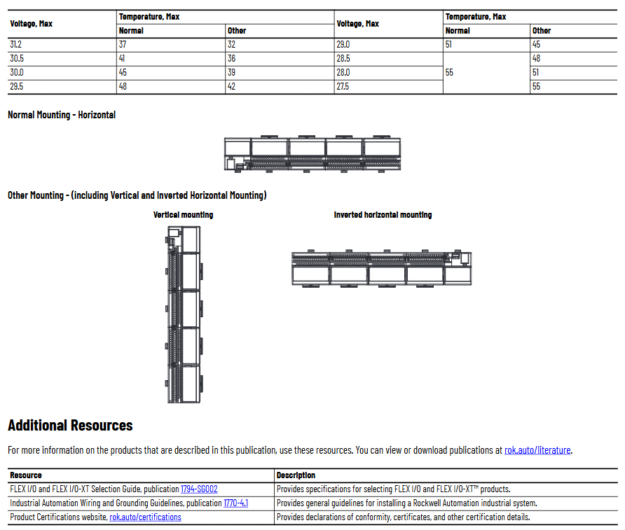
Environmental inspection: Confirm that the installation environment meets the requirements - pollution level 2 (industrial environment), overvoltage category II (EN/IEC 60664-1), altitude ≤ 2000 meters (no need to reduce capacity), and working temperature matching model (IB8/IB16 is -20~+55 ℃, IB32/IB32K is 0~+55 ℃).
Installation and wiring steps
(1) Module installation process
Base configuration: Rotate the key switch (position 3) on the terminal base to the "2" position (corresponding to the module type), ensuring that the Flexbus connector is fully pushed to the left and properly docked with the adjacent base/adapter.
Module alignment: Check if the pins at the bottom of the module are straight, align the alignment rod (position 6) of the module with the groove of the base (position 5), press the module evenly until the locking mechanism (position 2) clicks into the base, and confirm that the module is securely attached to the base.
Cleaning and inspection: During installation, avoid metal debris and wire residue from falling into the module to prevent short circuit damage after power on; After installation, check if all connections are secure and if the pins are not bent.
(2) Wiring method by model
1. 1794-IB8/IB16 (with 1794-TB3/TB3S base)
Wiring steps and operation details
Connect the signal line of the input device to the corresponding terminal of "A row (0-15)" (e.g. Input 0 is connected to A-0, Input 1 is connected to A-1)
Connect the+V DC power cord of the input device to the corresponding terminal of "C row (34-51)" (such as Input 0 connected to C-35), and all+V terminals in C row are internally connected; Connect the DC common terminal (3-wire device) to the corresponding terminal of "B row (16-33)" (such as Input 0 connected to B-17), and the B row common terminal is internally connected
Main power connection+V DC connection C-34, DC common terminal B-16
If the daisy chain extension needs to supply power to the next base, use jumper wires to connect the current base C-51 (+V) to the next base C-34, and B-33 (common terminal) to the next base B-16
2. 1794-IB32/IB32K (with 1794-TB32/TB32S base)
The module is divided into two sets of inputs (0-15, 16-31) and requires independent wiring:
Input 0-15: Connect the signal line to "A row (0-15)",+V1 to C row 35/37/39/41, COM1 to C row 36/38/40/42;
Input 16-31: Connect the signal line to "B row (17-32, skip 16/33)",+V2 to C row 43/45/47/49, COM2 to C row 44/46/48/50;
When expanding,+V1 jumps to the next base power terminal through C-41, and COM1 jumps to C-42; +V2 jumps through C-49, COM2 jumps through C-50.
(3) Wiring precautions
2-wire devices only need to connect the signal line and power line, while 3-wire devices require an additional connection to the common terminal;
The insulation layer of the wire needs to be stripped to a suitable length (to avoid short circuits caused by excessive exposure), and the torque of the terminal screws needs to meet the requirements of the base (usually 0.6-0.8 Nm);
Grounding needs to be achieved through DIN rails, which are fixed every 200 millimeters. End anchors need to be installed at both ends to ensure continuous grounding and low impedance.
Module configuration method
(1) Core configuration parameters
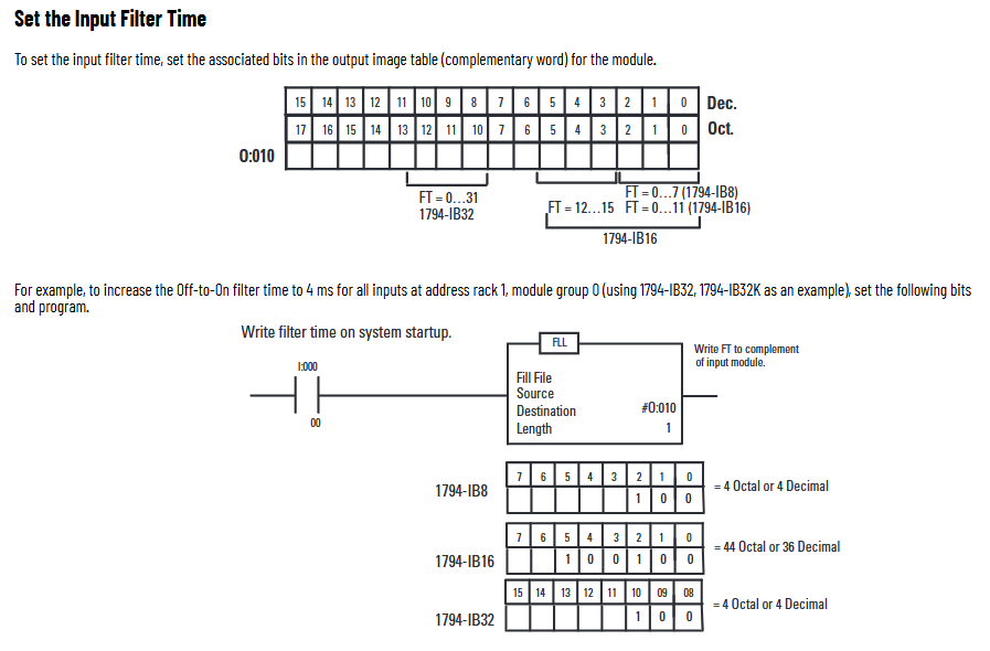
The module sets the input filtering time through the "configuration word (handwriting)", and the memory mapping and filtering control bits are different for different models. The core adjusts the signal stability through the "input filtering time (FT)" to avoid interference and false triggering.
(2) Filter time setting
Filter time options: selected through 3 binary bits (FT0-FT2), default 0.25 ms, optional 0.5 ms, 1 ms, 2 ms, 4 ms, 8 ms, 16 ms, 32 ms (see Table 6 for specific correspondence).
Configuration position by model:
1794-IB8: The filtering control bit corresponds to the 0-2 bits of "Write 1" and controls all 8 input channels;
1794-IB16: Control Input 0-11 with 0-2 bits, Input 12-15 with 3-5 bits, and support counter function (Input 15 can be set as fast input/standard input, and needs to be configured through CF/CR bits);
1794-IB32/IB32K: The filtering control bit corresponds to bits 8-10 of "Write 1" and controls all 32 input channels.
Configuration example: If you need to set the filtering time of 1794-IB8 to 4 ms, you need to write binary "101" (corresponding to decimal 5) to the "Write 1" address at system startup to ensure that the filtering parameters take effect after the module is powered on.
Technical specifications and certification
(1) Core electrical specifications
Model Number of input channels Rated voltage Conducting current (typical) Turning off current (maximum) Isolation voltage Maximum power consumption
1794-IB8 8 (sinking type) 24V DC 8 mA 1.5 mA 50V DC (850V DC test for 60s) 3.5 W
1794-IB16 16 (sinking type) 24V DC 8 mA 1.5 mA 50V DC (707V DC test for 60s) 6.1 W
1794-IB32 32 (sinking type) 24V DC 4.1 mA 1.5 mA 50V DC (2121V DC test for 2s) 6.0 W
1794-IB32K 32 (sinking type) 24V DC 4.1 mA 1.5 mA 50V DC (2121V DC test for 2s) 6.0 W
(2) Environmental and mechanical specifications
Environmental parameters: working humidity of 5% -95% (no condensation), storage temperature of -40~+85 ℃, vibration (working) of 5 g @ 10-500 Hz (IEC 60068-2-6), impact (working) of 30 g (IEC 60068-2-27);
Mechanical parameters: Module size (with base) 94 × 94 × 69 mm (3.7 × 3.7 × 2.7 inches), weight 71-79 g, no shell (open type), relying on external shell protection.
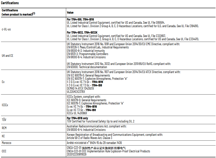
(3) Compliance certification
The module has passed multiple international certifications to ensure compliant use worldwide, with core certifications including:
Safety certification: UL (Industrial Control Equipment, Class I Division 2 Hazardous Areas, USA/Canada), CSA, TUV (IB16 supports SIL 2 functional safety);
Electromagnetic compatibility (EMC): EN 61326-1, IEC 61000-6-2/4, in compliance with anti-interference and radiation requirements for industrial environments;
Dangerous Place Certification: ATEX (European Zone 2), IECEx (International Zone 2), UKEX (UK Zone 2);
Environmental certification: Compliant with the EU RoHS Directive (2011/65/EU) and China CCC Explosion proof Certification (CNCA-C23-01).
- YOKOGAWA
- Reliance
- ADVANCED
- SEW
- ProSoft
- WATLOW
- Kongsberg
- FANUC
- VSD
- DCS
- PLC
- man-machine
- Covid-19
- Energy and Gender
- Energy Access
- Renewable Integration
- Energy Subsidies
- Energy and Water
- Net zero emission
- Energy Security
- Critical Minerals
- A-B
- petroleum
- Mine scale
- Sewage treatment
- cement
- architecture
- Industrial information
- New energy
- Automobile market
- electricity
- Construction site
- HIMA
- ABB
- Rockwell
- Schneider Modicon
- Siemens
- xYCOM
- Yaskawa
- Woodward
- BOSCH Rexroth
- MOOG
- General Electric
- American NI
- Rolls-Royce
- CTI
- Honeywell
- EMERSON
- MAN
- GE
- TRICONEX
- Control Wave
- ALSTOM
- AMAT
- STUDER
- KONGSBERG
- MOTOROLA
- DANAHER MOTION
- Bentley
- Galil
- EATON
- MOLEX
- Triconex
- DEIF
- B&W
- ZYGO
- Aerotech
- DANFOSS
- KOLLMORGEN
- Beijer
- Endress+Hauser
- schneider
- Foxboro
- KB
- REXROTH
- YAMAHA
- Johnson
- Westinghouse
- WAGO
- TOSHIBA
- TEKTRONIX
- BENDER
- BMCM
- SMC
- HITACHI
- HIRSCHMANN
- XP POWER
- Baldor
- Meggitt
- SHINKAWA
- Other Brands
- UniOP
- KUKA
- IBA
- Beckhoff
- ADLINK
-
Beckhoff EP9224-0037 - 4-Channel Power Distribution Box EtherCAT
-
Beckhoff CX2900-0026 - Solid State Flash Memory Card 20GB CFast
-
Beckhoff BK7500 - SERCOS Interface Fieldbus Bus Coupler Terminal
-
Beckhoff Ep2328-0002 - 4-Channel Input 4-Channel Output EtherCAT Box IP67
-
Beckhoff CX1020-0111 - Controller Kit Combo Interface Modules
-
B&R X20AI2237 - X20 System Analog Input Interface Module
-
Beckhoff CP2221-0010 - Multi-Touch Built-In Panel PC Touchscreen
-
Beckhoff CX1500-M310 - Fieldbus Master Interface Module 24V
-
Beckhoff CX2100-0904 - Power Charging Module Smart UPS Extension
-
Beckhoff CP3918-0000 - Multi-Touch Control Panel 18.5-Inch Monitor
-
Beckhoff CP2915-0000 - 15-Inch Multi-Touch Built-In Control Panel
-
Beckhoff CP7037-1027 - HMI Industrial Control Panel Built-In PC
-
Beckhoff EL3152 - 2-Channel Analog Input Terminal 4-20mA EtherCAT
-
Beckhoff CP6607-0000-0020 - 5.7-Inch Built-In Panel PC HMI Touch
-
Beckhoff EJ1809-0000 - 16-Channel Digital Input Pluggable Signal Level Terminal
-
Beckhoff AM8563-0N10-0000 - Synchronous Servo Motor
-
Beckhoff AX2006-S60600-520 - Compact Servo Drive Inverter
-
Beckhoff AM8053-0K20-0000 - Servo Motor with Planetary Gearbox AG3210
-
Beckhoff AM8042-0FH1-0000 - Synchronous Servo Motor
-
Rexroth R911338600 - IndraControl V HMI Terminal Beckhoff PCI Card FC9002
-
Beckhoff AX5125-0000 - 3 Phase Industrial Servo Drive 1000Hz
-
Beckhoff EP2328-0002 - 4-Channel Digital Input 4-Channel Output EtherCAT Box
-
B&R 7CP476-02 - System 2005 RTD CPU Module 3IF681.86 Interface
-
Beckhoff AX8620-0000-0000 - Power Supply Module Axis Drive System
-
Beckhoff CX1010-0111 - PLC Module CPU Controller 24V
-
Beckhoff AM8043-0H10-0000 - Synchronous Servo Motor
-
Beckhoff C6240-1009 - Control Cabinet Industrial PC Mainframe
-
Beckhoff BX8000-0000 - Bus Terminal Controller HW 4.4 Standalone
-
Beckhoff CP7721-1089-0020 - 12.1-Inch Touch Screen HMI Panel PC
-
Beckhoff CP7132-0001 - Industrial Built-In Panel PC Screen
-
Beckhoff CP2912-0010 - Multi-Touch Built-In Control Panel Display
-
Beckhoff CP2915-0000 - 15-Inch Multi-Touch Built-In Control Panel
-
Beckhoff AM8532-1EN0-0000 - Synchronous Servo Motor
-
Beckhoff AX5203-0000 - 2-Channel Digital Compact Servo Drive
-
Beckhoff CX2020-0141 - Embedded PC Core CPU Module
-
Beckhoff CP6832-0002-0010 - Built-In Industrial Control Panel Display
-
Beckhoff CX5020-0112 - Embedded PC CPU Control Module
-
Beckhoff CX5140-0175 - 4GB Embedded PC CPU Unit 24V
-
Beckhoff EL3681-0030 - Digital Multimeter Calibration Terminal EtherCAT
-
Beckhoff CP7201-1000-0000 - Industrial PC Touch Screen HMI Monitor
-
Beckhoff CP7232-1001-0000 - Industrial Panel PC Touch Screen
-
Beckhoff C6930-1032-0040 - Control Cabinet Industrial PC System
-
Beckhoff AX5125-0000 - 3 Phase Industrial Servo Drive 1000Hz
-
Beckhoff CP3916-1424-0000 - Multi-Touch Built-In Control Panel
-
B&R 1900071142 - Lemoine Fieldbus Communication Interface Module
-
Beckhoff EL2872 - 16-Channel Ribbon Cable Digital Output Terminal
-
Beckhoff CX2030-0120 - Embedded PC CPU Base Module Controller
-
Beckhoff CP3919-0000 - 19-Inch Multi-Touch Control Panel Touchscreen
-
Beckhoff AX5101-0000-0202 - Servo Driver Compact Intelligent Drive 180V
-
Beckhoff CX5130-0135 - Embedded PC Controller Module
-
Beckhoff CP3719-1061-0010 - Multi-Touch Panel PC Outer Housing Enclosure
-
Beckhoff CP3919-1033-0000 - 19-Inch Touch Industrial Panel Keyboard
-
Beckhoff CX5020-0111 - Embedded PC PLC CPU Module
-
Beckhoff FC5102-0000 - 2-Channel CANopen PCI Control Board Card
-
Beckhoff CX9001-1101 - Embedded PC CPU Network I/O System Module
-
Beckhoff CX1100-0920 - Smart Position Sensor Interface Module
-
B&R 4P3040.01-490 - Operator Panel PLC Interface Communication Module
-
Beckhoff CP2612-0000 - Dual-Touch Built-In Panel PC HMI
-
Beckhoff CP7002-1043-0010 - Touchscreen Display HMI Panel Terminal
-
Beckhoff CX9020-0115 - Embedded PC Controller Module
-
Beckhoff CX5140-0155 - 4GB Embedded PC CPU Module Die Industry
-
B&R 7DI435.7 - System 2005 Universal Digital Input Output Module
-
Bihl+Wiedemann BWU1568 - AS-i Master to Profibus Gateway Module
-
Beckhoff C6920-0070 - Control Cabinet Industrial PC 8GB Win 10
-
B&R X20AI2322 - 2-Channel Temperature Analog Input Module
-
Beckhoff CP2912-0000 - 12-Inch Touchscreen Display Monitor Screen
-
Beckhoff CP6022-1001-0010 - 15-Inch Built-In Control Panel
-
Beckhoff AM8031-0D10-0000 - Synchronous Servo Motor
-
Beckhoff CX5010-0111 - Embedded PC Controller CPU Module
-
Beckhoff CP7232-1000-0000 - Industrial Panel PC Touch Display Screen
-
Beckhoff CP7802-0011-0000 - 15-Inch Industrial Touchscreen Control Panel
-
Beckhoff C6320 - Control Cabinet Industrial PC
-
Beckhoff CX1030-0012 - Basic CPU Module Windows CE 6.0
-
Beckhoff CP2919-0000 - Installation Multi-Touch Control Panel
-
Beckhoff CX1020-0000 - Controller Set Stack System Pack
-
B&R 3DO480.6 - System 2005 Digital Output Module
-
Beckhoff EL3101 - 1-Channel Analog Input Terminal Differential +/-10V
-
Beckhoff AX8108-0200-0000 - Axis Feed Module Servo Drive
-
Beckhoff CP7802-1241-0010 - 15-Inch Industrial Touchscreen Control Panel
-
Beckhoff FC2002-0000 - 2-Channel Lightbus Data Acquisition PCI Card
-
Beckhoff CX5120-0155 - 2GB Embedded PC Intel Atom Controller
-
Beckhoff Cx9020-0111 - 1GB Basic CPU Module Embedded PC
-
Beckhoff CP6901-0001-0000 - 12-Inch Economy Built-In Control Panel
-
Beckhoff CX9020-0111 - Embedded PC CPU Basic Module
-
Beckhoff CX5130-0100 - 4GB Embedded PC CPU Module
-
Beckhoff CP2715-0010 - Multi-Touch Built-In Panel PC
-
Beckhoff CX2033-0175 - Embedded PC CPU Module Core i7
-
Beckhoff CP7201-1000-0000 - 12-Inch Touchscreen Panel PC AMAT Green Box
-
Beckhoff EL4038 - 8-Channel Analog Output Terminal 0-10V EtherCAT
-
Beckhoff CP6802-0000-0000 - Built-In Control Panel HMI Screen
-
Beckhoff AM8042-0F21-0000 - Synchronous Servo Motor
-
Beckhoff CX5120-0141 - Embedded PC Basic Controller Module
-
Beckhoff C6930-0050 - Control Cabinet Industrial PC System
-
Beckhoff CP6831-0002-0000 - Built-In Industrial Control Panel
-
Beckhoff CP6919-0001-0000 - Built-In Control Panel Display Unit
-
Beckhoff CP7201-1019-0030 - Built-In Panel PC HMI Monitor Screen
-
Beckhoff CP6809-0001-0000 - 6.5-Inch Touch Panel ELO Accutouch HMI
-
Beckhoff CX1020-0000 - Control Kit Combo Stack Units
-
Beckhoff cp3918-1012-0000 - 18.5-Inch Multi-Touch Control Panel
-
Beckhoff CX5140-0123 - 4GB Embedded PC CPU Module
-
Beckhoff C3230TP - Industrial PC Rackmount Workstation
-
Beckhoff CP6801-1006-0010 - Touch Panel HMI Display Unit
-
Beckhoff CX8010 - Embedded PC Controller Module
-
Beckhoff CP7011-0001 - Control Panel CRT Operator Pendant Monitor HMI
-
Beckhoff CX1010-0111 - Embedded PC CPU PLC Module 24V
-
Beckhoff CP2915-0000 - 15-Inch Multi-Touch Built-In Control Panel
-
Beckhoff CP7802 - Industrial Touch Screen Control Panel Monitor
-
Siemens 6AV7452-1AB00-0FB0 - Industrial PC Panel 877 Beckhoff PCI Cards
-
Beckhoff CP2612-0000 - Dual-Touch Integrated Panel Monitor Screen
-
Beckhoff CX5140-0175 - Embedded PC Core Controller
-
Beckhoff Cp6202-0001-0010 - Economy Built-In Panel PC System
-
Beckhoff C6320-0010 - Control Cabinet Industrial PC Unit
-
Beckhoff CP2919-0000 - Multi-Touch Built-In Control Panel Screen
-
Beckhoff CX9020-0111 - Embedded PC CPU Controller Module
-
B&R 3BP151.41 - System 2005 Backplane Base Module
-
Siemens 6AV7452-1AB00-0FB0 - Panel PC 877 with Beckhoff Communication Cards FC3101 FC7501
-
Beckhoff CX9001-1101 - Embedded PC System Fieldbus Module Bundle
-
Beckhoff CX1001-0122 - CPU Module PLC Controller 128MB RAM
-
Beckhoff CX5130-0175 - Embedded PC CPU Module Intel Atom Storage Card
-
Beckhoff C6140 - Industrial PC Tower Casing Pent 4 System
-
Beckhoff CX5020-0120 - Embedded PC Controller Core Module
-
Beckhoff C6017-0010 - Ultra-Compact Industrial PC
-
Beckhoff CP6809-0000-0000 - 6.5-Inch Industrial Panel Control Display
-
Beckhoff AX5021-0000-0000 - Brake Chopper Module Axis System
-
Beckhoff AM8031-0D10-0000 - Synchronous Servo Motor
-
Beckhoff CX8010 - Embedded PC Microcontroller Module
-
Beckhoff CP6202-1070-0070 - Built-In Panel PC HMI Touchscreen
-
Beckhoff C6920-0000 - Control Cabinet Industrial PC Module

K-JIANG

Add: Jimei North Road, Jimei District, Xiamen, Fujian, China
Tell:+86-15305925923