
K-WANG


BARTEC MODEX PROFIBUS 07-7331-2305 Series Interface Module
Comparison item model 07-7331-2305/000 model 07-7331-2305/1000
Output explosion-proof level Ex e (increased safety type) Ex i (intrinsic safety type)
Output voltage U2-0.2V (approximately 23.8V when U2 is 24V) DC 22V (when U2 ≥ 24V)
Single channel maximum output current 500mA-
Single channel internal resistance -301 Ω
Module loss power maximum 3.5W maximum 4.5W
Control object: 4-channel Ex e valve, 4-channel Ex i valve
BARTEC MODEX PROFIBUS 07-7331-2305 Series Interface Module
Module core information and functional differences
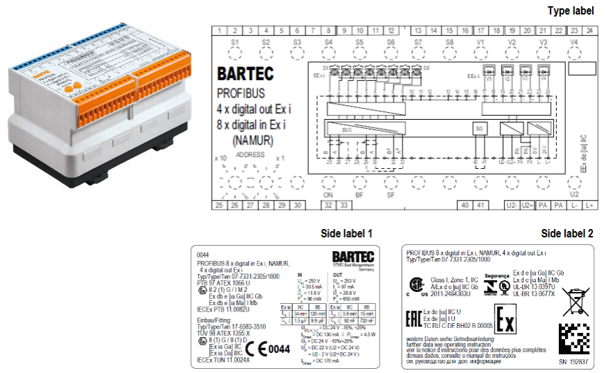
Both modules are PROFIBUS-DP interface devices with "4-channel digital output+8-channel digital input". The core difference lies in the explosion-proof level of the output terminal. The specific comparison is as follows:
Comparison item model 07-7331-2305/000 model 07-7331-2305/1000
Output explosion-proof level Ex e (increased safety type) Ex i (intrinsic safety type)
Output voltage U2-0.2V (approximately 23.8V when U2 is 24V) DC 22V (when U2 ≥ 24V)
Single channel maximum output current 500mA-
Single channel internal resistance -301 Ω
Module loss power maximum 3.5W maximum 4.5W
Control object: 4-channel Ex e valve, 4-channel Ex i valve
Common core functions:
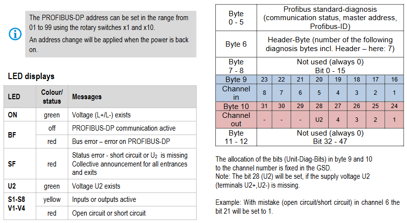
Input function: 8-channel Ex i intrinsic safety input, supporting NAMUR limit switches, mechanical contacts (compliant with EN/IEC 60947-5-6 standard), with wire breakage/short circuit detection;
Display function: Real time display of power supply (ON light), bus communication (BF light), status fault (SF light), output power supply (U2 light), and activation/fault status of each channel through LED;
Safety design: Short circuit protection (automatically cuts off output in case of short circuit), reverse polarity protection, supports cutting off actuator power through U2 terminal external emergency stop switch;
Communication and diagnosis: Connected to the control system through PROFIBUS-DP, it can transmit user data and diagnostic data (output disconnection/short circuit status), supporting SYNC (output status freeze) and FREEZE (input status freeze) functions.
Explosion proof certification and compliance
The module is designed for explosive hazardous environments and has passed multiple international certifications to meet compliance requirements in different regions
Certification System Certification Number/Directive Explosion proof Identification/Key Requirements
ATEX PTB 97 ATEX 1066 U, T Ü V 98 ATEX 1355 X II 2 (1) G Ex db e [ia Ga] IIC Gb; I M2 Ex db e [ia Ma] I Mb
IECEx PTB 11.0082U、TUN 11.0024X Ex db e [ia Ga] IIC Gb; Ex db e [ia Ma] I Mb
Regional Compliance CSA(2011-2484303U)、INMETRO(UL-BR 13.0397U)、EAC(RU C-DE.BH02.B.00005) CSA Identification: A/Ex d e [ia] IIC Gb
EU directives ATEX 2014/34/EU, RoHS 2011/65/EU, EMC 2014/30/EU comply with EN 60079 series explosion-proof standards and EN 60529 protection standards
Special explosion-proof requirements:
The module is marked with a "U" symbol and needs to be installed in an enclosure that complies with EN/IEC 60079-0 standard and has a protection level of not less than IP54;
If the shell is of Ex e increased safety type, it must meet the electrical clearance and creepage distance specified in Table 1+2 of IEC/EN 60079-7.
Key technical parameters
1. Electrical parameters (general)
Power supply voltage: Electronic part (L+/L -) DC 24V (20-30V); Output section (U2+/U2-) DC 24V (20-30V, supports emergency stop);
Input parameters (Ex i): U ₀=11.8V, I ₀=31mA, P ₀=90mW, linear characteristics, external inductance/capacitance limits vary with explosion-proof level (e.g. Ex ia IIC, L ₀ maximum 47mH, C ₀ maximum 1.5 μ F);
Bus interface: RS485 (screw terminal), PROFIBUS-DP address set through rotary switch (01-99, effective after power failure);
Isolation design: Galvanic isolation is used between power supply, bus, circuit, output, and input.
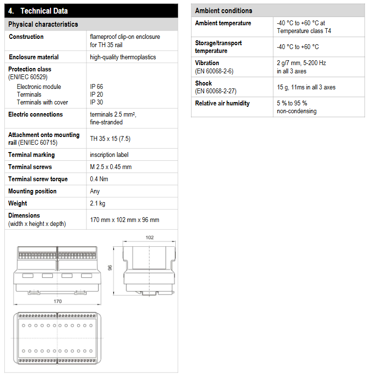
2. Physical and environmental parameters
Protection level: Electronic module IP66, terminal IP20 (uncovered)/IP30 (covered);
Installation: Suitable for TH35 × 15 (7.5) standard guide rail (EN/IEC 60715), with any installation direction;
Size and weight: 170mm x 96mm x 102mm (width x height x depth), weight 2.1kg;
Environmental conditions: working/storage temperature -40 ℃~+60 ℃ (T4 temperature level), relative humidity 5% -95% (no condensation); Anti vibration (2g/7mm, 5-200Hz, 3-axis), anti impact (15g, 11ms, 3-axis).
3. Terminals and Connections
Terminal specification: 2.5mm ² multi strand wire, terminal screw M2.5 × 0.45mm, tightening torque 0.4Nm;
Grounding requirements: 1-2 grounding terminals should be installed on the right side of the module, and the PA terminal should be connected to the grounding terminal with a 2.5mm ² wire.
Installation and operation specifications
1. Installation requirements
Installation personnel: must have the qualification to install electrical equipment in explosive hazardous areas and have read and understood the instructions;
Preprocessing: Before installation, check that the module is clean and undamaged, there is a power outage, and adjacent live parts are protected;
Operation steps: Insert the module into the guide rail until the buckle makes a sound, and tighten the terminal screws with a torque wrench at 0.4-0.7Nm.
2. Debugging and troubleshooting
Pre debugging inspection: installation correctness, shell integrity, wiring compliance, address and baud rate settings;
Priority for troubleshooting: LED status (such as BF red light indicating bus fault, SF red light indicating short circuit or U2 power failure) → Wiring/terminal fastening → Address/baud rate → Bus terminal and jumper → System restart (required after address change).
3. Maintenance and disposal
Maintenance: No maintenance is required under normal use, and regular inspections by electricians are required according to EN/IEC 60079-17/19;
Repair: Self repair is prohibited, please contact BARTEC GmbH;
Disposal: Belonging to B2B equipment under the WEEE directive, it needs to be disposed of in accordance with local regulations and can be returned to BARTEC (with shipping costs borne by the sender), WEEE number DE 95940350.
- YOKOGAWA
- Reliance
- ADVANCED
- SEW
- ProSoft
- WATLOW
- Kongsberg
- FANUC
- VSD
- DCS
- PLC
- man-machine
- Covid-19
- Energy and Gender
- Energy Access
- Renewable Integration
- Energy Subsidies
- Energy and Water
- Net zero emission
- Energy Security
- Critical Minerals
- A-B
- petroleum
- Mine scale
- Sewage treatment
- cement
- architecture
- Industrial information
- New energy
- Automobile market
- electricity
- Construction site
- HIMA
- ABB
- Rockwell
- Schneider Modicon
- Siemens
- xYCOM
- Yaskawa
- Woodward
- BOSCH Rexroth
- MOOG
- General Electric
- American NI
- Rolls-Royce
- CTI
- Honeywell
- EMERSON
- MAN
- GE
- TRICONEX
- Control Wave
- ALSTOM
- AMAT
- STUDER
- KONGSBERG
- MOTOROLA
- DANAHER MOTION
- Bentley
- Galil
- EATON
- MOLEX
- Triconex
- DEIF
- B&W
- ZYGO
- Aerotech
- DANFOSS
- KOLLMORGEN
- Beijer
- Endress+Hauser
- schneider
- Foxboro
- KB
- REXROTH
- YAMAHA
- Johnson
- Westinghouse
- WAGO
- TOSHIBA
- TEKTRONIX
- BENDER
- BMCM
- SMC
- HITACHI
- HIRSCHMANN
- XP POWER
- Baldor
- Meggitt
- SHINKAWA
- Other Brands
- UniOP
- KUKA
- IBA
- Beckhoff
- ADLINK
-
Beckhoff EP9224-0037 - 4-Channel Power Distribution Box EtherCAT
-
Beckhoff CX2900-0026 - Solid State Flash Memory Card 20GB CFast
-
Beckhoff BK7500 - SERCOS Interface Fieldbus Bus Coupler Terminal
-
Beckhoff Ep2328-0002 - 4-Channel Input 4-Channel Output EtherCAT Box IP67
-
Beckhoff CX1020-0111 - Controller Kit Combo Interface Modules
-
B&R X20AI2237 - X20 System Analog Input Interface Module
-
Beckhoff CP2221-0010 - Multi-Touch Built-In Panel PC Touchscreen
-
Beckhoff CX1500-M310 - Fieldbus Master Interface Module 24V
-
Beckhoff CX2100-0904 - Power Charging Module Smart UPS Extension
-
Beckhoff CP3918-0000 - Multi-Touch Control Panel 18.5-Inch Monitor
-
Beckhoff CP2915-0000 - 15-Inch Multi-Touch Built-In Control Panel
-
Beckhoff CP7037-1027 - HMI Industrial Control Panel Built-In PC
-
Beckhoff EL3152 - 2-Channel Analog Input Terminal 4-20mA EtherCAT
-
Beckhoff CP6607-0000-0020 - 5.7-Inch Built-In Panel PC HMI Touch
-
Beckhoff EJ1809-0000 - 16-Channel Digital Input Pluggable Signal Level Terminal
-
Beckhoff AM8563-0N10-0000 - Synchronous Servo Motor
-
Beckhoff AX2006-S60600-520 - Compact Servo Drive Inverter
-
Beckhoff AM8053-0K20-0000 - Servo Motor with Planetary Gearbox AG3210
-
Beckhoff AM8042-0FH1-0000 - Synchronous Servo Motor
-
Rexroth R911338600 - IndraControl V HMI Terminal Beckhoff PCI Card FC9002
-
Beckhoff AX5125-0000 - 3 Phase Industrial Servo Drive 1000Hz
-
Beckhoff EP2328-0002 - 4-Channel Digital Input 4-Channel Output EtherCAT Box
-
B&R 7CP476-02 - System 2005 RTD CPU Module 3IF681.86 Interface
-
Beckhoff AX8620-0000-0000 - Power Supply Module Axis Drive System
-
Beckhoff CX1010-0111 - PLC Module CPU Controller 24V
-
Beckhoff AM8043-0H10-0000 - Synchronous Servo Motor
-
Beckhoff C6240-1009 - Control Cabinet Industrial PC Mainframe
-
Beckhoff BX8000-0000 - Bus Terminal Controller HW 4.4 Standalone
-
Beckhoff CP7721-1089-0020 - 12.1-Inch Touch Screen HMI Panel PC
-
Beckhoff CP7132-0001 - Industrial Built-In Panel PC Screen
-
Beckhoff CP2912-0010 - Multi-Touch Built-In Control Panel Display
-
Beckhoff CP2915-0000 - 15-Inch Multi-Touch Built-In Control Panel
-
Beckhoff AM8532-1EN0-0000 - Synchronous Servo Motor
-
Beckhoff AX5203-0000 - 2-Channel Digital Compact Servo Drive
-
Beckhoff CX2020-0141 - Embedded PC Core CPU Module
-
Beckhoff CP6832-0002-0010 - Built-In Industrial Control Panel Display
-
Beckhoff CX5020-0112 - Embedded PC CPU Control Module
-
Beckhoff CX5140-0175 - 4GB Embedded PC CPU Unit 24V
-
Beckhoff EL3681-0030 - Digital Multimeter Calibration Terminal EtherCAT
-
Beckhoff CP7201-1000-0000 - Industrial PC Touch Screen HMI Monitor
-
Beckhoff CP7232-1001-0000 - Industrial Panel PC Touch Screen
-
Beckhoff C6930-1032-0040 - Control Cabinet Industrial PC System
-
Beckhoff AX5125-0000 - 3 Phase Industrial Servo Drive 1000Hz
-
Beckhoff CP3916-1424-0000 - Multi-Touch Built-In Control Panel
-
B&R 1900071142 - Lemoine Fieldbus Communication Interface Module
-
Beckhoff EL2872 - 16-Channel Ribbon Cable Digital Output Terminal
-
Beckhoff CX2030-0120 - Embedded PC CPU Base Module Controller
-
Beckhoff CP3919-0000 - 19-Inch Multi-Touch Control Panel Touchscreen
-
Beckhoff AX5101-0000-0202 - Servo Driver Compact Intelligent Drive 180V
-
Beckhoff CX5130-0135 - Embedded PC Controller Module
-
Beckhoff CP3719-1061-0010 - Multi-Touch Panel PC Outer Housing Enclosure
-
Beckhoff CP3919-1033-0000 - 19-Inch Touch Industrial Panel Keyboard
-
Beckhoff CX5020-0111 - Embedded PC PLC CPU Module
-
Beckhoff FC5102-0000 - 2-Channel CANopen PCI Control Board Card
-
Beckhoff CX9001-1101 - Embedded PC CPU Network I/O System Module
-
Beckhoff CX1100-0920 - Smart Position Sensor Interface Module
-
B&R 4P3040.01-490 - Operator Panel PLC Interface Communication Module
-
Beckhoff CP2612-0000 - Dual-Touch Built-In Panel PC HMI
-
Beckhoff CP7002-1043-0010 - Touchscreen Display HMI Panel Terminal
-
Beckhoff CX9020-0115 - Embedded PC Controller Module
-
Beckhoff CX5140-0155 - 4GB Embedded PC CPU Module Die Industry
-
B&R 7DI435.7 - System 2005 Universal Digital Input Output Module
-
Bihl+Wiedemann BWU1568 - AS-i Master to Profibus Gateway Module
-
Beckhoff C6920-0070 - Control Cabinet Industrial PC 8GB Win 10
-
B&R X20AI2322 - 2-Channel Temperature Analog Input Module
-
Beckhoff CP2912-0000 - 12-Inch Touchscreen Display Monitor Screen
-
Beckhoff CP6022-1001-0010 - 15-Inch Built-In Control Panel
-
Beckhoff AM8031-0D10-0000 - Synchronous Servo Motor
-
Beckhoff CX5010-0111 - Embedded PC Controller CPU Module
-
Beckhoff CP7232-1000-0000 - Industrial Panel PC Touch Display Screen
-
Beckhoff CP7802-0011-0000 - 15-Inch Industrial Touchscreen Control Panel
-
Beckhoff C6320 - Control Cabinet Industrial PC
-
Beckhoff CX1030-0012 - Basic CPU Module Windows CE 6.0
-
Beckhoff CP2919-0000 - Installation Multi-Touch Control Panel
-
Beckhoff CX1020-0000 - Controller Set Stack System Pack
-
B&R 3DO480.6 - System 2005 Digital Output Module
-
Beckhoff EL3101 - 1-Channel Analog Input Terminal Differential +/-10V
-
Beckhoff AX8108-0200-0000 - Axis Feed Module Servo Drive
-
Beckhoff CP7802-1241-0010 - 15-Inch Industrial Touchscreen Control Panel
-
Beckhoff FC2002-0000 - 2-Channel Lightbus Data Acquisition PCI Card
-
Beckhoff CX5120-0155 - 2GB Embedded PC Intel Atom Controller
-
Beckhoff Cx9020-0111 - 1GB Basic CPU Module Embedded PC
-
Beckhoff CP6901-0001-0000 - 12-Inch Economy Built-In Control Panel
-
Beckhoff CX9020-0111 - Embedded PC CPU Basic Module
-
Beckhoff CX5130-0100 - 4GB Embedded PC CPU Module
-
Beckhoff CP2715-0010 - Multi-Touch Built-In Panel PC
-
Beckhoff CX2033-0175 - Embedded PC CPU Module Core i7
-
Beckhoff CP7201-1000-0000 - 12-Inch Touchscreen Panel PC AMAT Green Box
-
Beckhoff EL4038 - 8-Channel Analog Output Terminal 0-10V EtherCAT
-
Beckhoff CP6802-0000-0000 - Built-In Control Panel HMI Screen
-
Beckhoff AM8042-0F21-0000 - Synchronous Servo Motor
-
Beckhoff CX5120-0141 - Embedded PC Basic Controller Module
-
Beckhoff C6930-0050 - Control Cabinet Industrial PC System
-
Beckhoff CP6831-0002-0000 - Built-In Industrial Control Panel
-
Beckhoff CP6919-0001-0000 - Built-In Control Panel Display Unit
-
Beckhoff CP7201-1019-0030 - Built-In Panel PC HMI Monitor Screen
-
Beckhoff CP6809-0001-0000 - 6.5-Inch Touch Panel ELO Accutouch HMI
-
Beckhoff CX1020-0000 - Control Kit Combo Stack Units
-
Beckhoff cp3918-1012-0000 - 18.5-Inch Multi-Touch Control Panel
-
Beckhoff CX5140-0123 - 4GB Embedded PC CPU Module
-
Beckhoff C3230TP - Industrial PC Rackmount Workstation
-
Beckhoff CP6801-1006-0010 - Touch Panel HMI Display Unit
-
Beckhoff CX8010 - Embedded PC Controller Module
-
Beckhoff CP7011-0001 - Control Panel CRT Operator Pendant Monitor HMI
-
Beckhoff CX1010-0111 - Embedded PC CPU PLC Module 24V
-
Beckhoff CP2915-0000 - 15-Inch Multi-Touch Built-In Control Panel
-
Beckhoff CP7802 - Industrial Touch Screen Control Panel Monitor
-
Siemens 6AV7452-1AB00-0FB0 - Industrial PC Panel 877 Beckhoff PCI Cards
-
Beckhoff CP2612-0000 - Dual-Touch Integrated Panel Monitor Screen
-
Beckhoff CX5140-0175 - Embedded PC Core Controller
-
Beckhoff Cp6202-0001-0010 - Economy Built-In Panel PC System
-
Beckhoff C6320-0010 - Control Cabinet Industrial PC Unit
-
Beckhoff CP2919-0000 - Multi-Touch Built-In Control Panel Screen
-
Beckhoff CX9020-0111 - Embedded PC CPU Controller Module
-
B&R 3BP151.41 - System 2005 Backplane Base Module
-
Siemens 6AV7452-1AB00-0FB0 - Panel PC 877 with Beckhoff Communication Cards FC3101 FC7501
-
Beckhoff CX9001-1101 - Embedded PC System Fieldbus Module Bundle
-
Beckhoff CX1001-0122 - CPU Module PLC Controller 128MB RAM
-
Beckhoff CX5130-0175 - Embedded PC CPU Module Intel Atom Storage Card
-
Beckhoff C6140 - Industrial PC Tower Casing Pent 4 System
-
Beckhoff CX5020-0120 - Embedded PC Controller Core Module
-
Beckhoff C6017-0010 - Ultra-Compact Industrial PC
-
Beckhoff CP6809-0000-0000 - 6.5-Inch Industrial Panel Control Display
-
Beckhoff AX5021-0000-0000 - Brake Chopper Module Axis System
-
Beckhoff AM8031-0D10-0000 - Synchronous Servo Motor
-
Beckhoff CX8010 - Embedded PC Microcontroller Module
-
Beckhoff CP6202-1070-0070 - Built-In Panel PC HMI Touchscreen
-
Beckhoff C6920-0000 - Control Cabinet Industrial PC Module

K-JIANG

Add: Jimei North Road, Jimei District, Xiamen, Fujian, China
Tell:+86-15305925923