
K-WANG


Woodward 2301A 9907 series electronic load distribution and speed controller
Woodward 2301A 9907 series electronic load distribution and speed controller
Product basic information
1. Core functions and positioning
Core function: Simultaneously achieve two major functions of speed control and load distribution - speed control maintains stable speed of the prime mover (engine/turbine), load distribution ensures proportional load sharing when multiple units are connected in parallel, avoiding single unit overload or uneven load.
Control mode:
Synchronous mode (Isochronous): suitable for single unit operation or multi unit isolated bus parallel connection, maintaining constant speed, requiring automatic power transmission (APTL), import and export control and other load adjustment accessories.
Droop mode: suitable for parallel connection of units to an infinite power grid or with non compatible governor units. The speed decreases with increasing load, and the droop rate can be adjusted through a potentiometer (formula:% droop=(no-load speed - full load speed)/no-load speed x 100).
2. Model and Key Parameters
(1) Model classification (9907 series)
The differences between different models are reflected in the actuator current, action direction, voltage level, and deceleration ramp function. The core parameters are shown in the table below:
Model actuator current action direction voltage level deceleration ramp
9907-020 0-200mA positive high voltage none
9907-021 0-200mA Reverse High Voltage None
9907-238 0-200mA positive low voltage none
9907-239 0-200mA Reverse Low Voltage None
9903-327 0-200mA Reverse Low Voltage None
Forward/Reverse Action: During forward action, the increase in actuator voltage corresponds to an increase in fuel/steam; When reversing the action, the decrease in voltage corresponds to an increase in fuel/steam (default to full fuel when power is off, compatible with mechanical backup governor).
Voltage level: Low voltage type (18-40VDC), high voltage type (90-150VDC or 88-132VAC), to be matched according to the system power supply.
(2) Key technical parameters
Speed range: Select four frequency ranges (500-1500Hz, 1000-3000Hz, 2000-6000Hz, 4000-12000Hz) through switch S1. The factory default is 2000-6000Hz, which needs to be matched based on the rated speed of the prime mover and the number of teeth on the speed measuring gear (formula: sensor frequency=number of teeth on the gear x speed (rpm)/60).
Actuators and sensors: support 0-200mA actuator output; Speed measurement requires the use of a magneto electric sensor (magnetic head), with a minimum signal requirement of 1.0Vrms (starting speed) and a maximum of 25Vrms (rated speed). The gap between the sensor and the gear should be controlled between 0.25-1.0mm.
Installation specifications and wiring
1. Installation environment and location requirements
Environmental conditions: working temperature -40-85 ℃ (-40-185 ℉), relative humidity 10% -95% (no condensation); Avoid direct contact with water, vibration sources, and strong electromagnetic interference equipment (such as high-voltage cabinets and high current cables).
Installation restrictions: It is prohibited to install directly on the engine; Reserved heat dissipation space is required (with a ventilation gap of ≥ 3cm and a distance of ≥ 15cm from heating components), and a vertical installation inclination angle of ≤± 45 ° (when there is no forced ventilation).
2. Electrical wiring and shielding requirements
(1) Core interface wiring
The controller terminals are concentrated on the front panel, and the key interfaces and wiring requirements are as follows:
Interface type, terminal number, wiring requirements, precautions
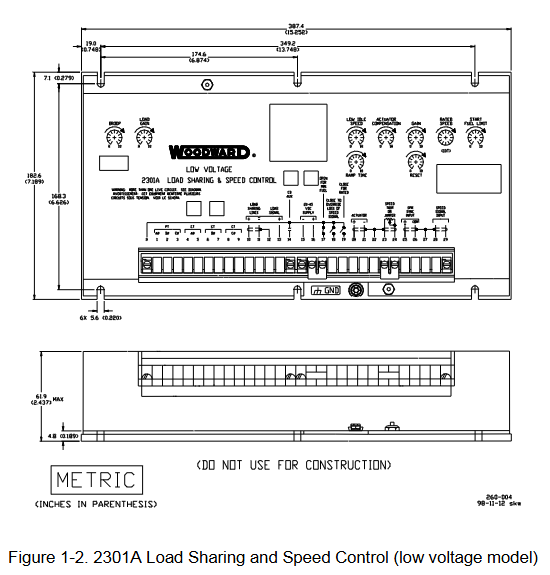
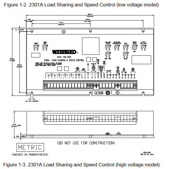
Low voltage power input type (15-, 16+); High voltage type (0, 16) low voltage: 18-40VDC; High voltage: 90-150VDC/88-132VAC requires installation of XT-FIL-1/2 anti-interference filter (mandatory in maritime scenarios); Terminal creepage distance ≥ 6.5mm (compliant with the EU Low Voltage Directive)
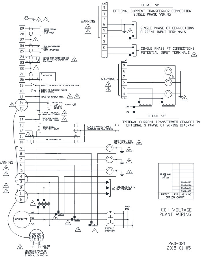
Speed sensors 28 (signal+), 29 (signal -), and 27 (shielded) use shielded twisted pair cables. Only one end of the shielding layer is connected to terminal 27, and the other end is suspended with an insulation sensor gap of 0.25-1.0mm. The radial runout of the gear is ≤ 0.5mm
The output of the actuator is 20 (+), 21 (-), and 22 (shielding), and the shielding layer is only connected to terminal 22. It is forbidden to connect the actuator or other grounded actuators. The coil resistance is about 35 Ω, and open/short circuits need to be checked
Load sensor (CT/PT) CT (4-9), PT (1-3) CT secondary output 3-7A (rated 5A), PT secondary 100-120VAC/200-240VAC CT open circuit will generate high voltage, short circuit or power off before wiring
Load distribution lines 10 (+), 11 (-), and 12 (shielded) are shielded twisted pair cables. When multiple units are connected in parallel, the shielding layer is continuously connected without the need for additional relays. The controller is equipped with a built-in load distribution relay
(2) Shielding and anti-interference
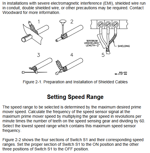
All signal cables (speed measurement, actuator, load distribution lines) must use shielded twisted pair cables, with the shielding layer only grounded at the controller end (terminals 22, 27, 12) and the other end suspended to avoid the formation of ground current.
Strong current cables (power supply, CT/PT) should be wired separately from signal cables to avoid parallel laying; Severe electromagnetic interference scenarios require the use of metal conduits or double shielded cables.
3. Installation inspection process
Mechanical inspection: The actuator and the connecting rod of the prime mover are not loose/stuck, and the actuator lever does not touch the mechanical limit when the fuel is at its minimum position (to prevent the inability to stop the machine).
Wiring inspection: Check the power polarity, CT/PT phase, terminals are not loose, and the shielding layer is connected correctly according to the wiring diagram.
Sensor inspection: The gap between the magnetic head and the gear is 0.25-1.0mm, and there are no metal debris; Measure the sensor resistance (100-300 Ω) before powering on to determine if there is an open/short circuit.
Operation and debugging process
1. Initial settings before startup
All potentiometers must be pre-set according to the following requirements to avoid overload or overspeed during startup:
Initial setting function of potentiometer
Rated speed minimum (counterclockwise to the bottom) to avoid excessive speed during startup
Reset the middle position to adjust the speed and restore the speed
Speed stability when adjusting load changes in the middle position of gain (GAIN)
Ramp TIME (clockwise to the end) extends the acceleration time to prevent overspeed during startup
Low IDLE SPEED Maximum (clockwise to the bottom) ensures stable idle after starting
Adjust the load distribution ratio in the middle position of the load gain (LOAD GAIN)
DROOP Minimum (counterclockwise to the bottom) Initial default synchronization mode
ACTUATOR COMPENSATION for diesel/gas engines: 2; Gasoline engine/turbine: 6 compensating actuator response delays
Start Fuel Limit Maximum (clockwise to the bottom) to prevent excessive fuel smoke during startup
2. Startup and dynamic debugging
(1) Startup steps
Close the "rated speed" contact (terminal 19), close the droop contact (terminal 14), and set to synchronous mode.
Connect the power to the controller and calibrate the speed using a signal generator: Connect terminals 28-29, set the rated frequency, and slowly adjust the "rated speed" potentiometer to stabilize the actuator voltage at the intermediate value (not maximum/minimum).
Start the prime mover and observe if the speed is stable. If there is a rapid fluctuation (hunting), decrease the "gain" counterclockwise; If there is a slow fluctuation, increase the "reset" clockwise.
(2) Key parameter calibration
Low idle adjustment: Disconnect the "rated speed" contact (terminal 19) and adjust the "low idle" potentiometer counterclockwise to the recommended idle speed (higher than the fuel mechanical limit speed).
Load gain calibration: When a single unit is running synchronously, load to full load and adjust the "load gain" potentiometer to make the voltage between terminals 11 (-) and 13 (+) 6.0V (3.0V at half load, proportionally adjusted).
Sag adjustment:
Isolated load: Disconnect the droop contact, adjust the rated speed under no-load, and adjust the "droop" potentiometer to the target droop rate under full load (e.g. 5% droop corresponds to 60Hz no-load → 57Hz full load).
Grid parallel connection: calculate the full load frequency (rated frequency × (1+droop rate)), set the frequency at no-load, close the circuit breaker and then adjust "droop" and "load gain" to full load.
3. Parallel operation debugging
When multiple units are connected in parallel, the following conditions must be met:
All units have the same no-load speed (synchronous mode).
The load gain voltage is consistent (full load 6.0V).
CT/PT phase consistency: Ensure the CT wiring phase is correct and avoid circulating current through the "phase correction process" (see pages 23-25 of the manual).
Load distribution line connection: All units have 10 (+) and 11 (-) terminals connected in parallel, and the shielding layer is continuously grounded.
Troubleshooting and Maintenance
1. Common fault handling
The manual provides a detailed troubleshooting table, and the core faults and solutions are as follows:
Possible causes and solutions for the fault phenomenon
The prime mover cannot start, the actuator does not operate, and the polarity of the power supply is reversed/there is no voltage; The fuel limit for starting is too low; Check the polarity and voltage of the power supply when the speed signal is not cleared and the fault circuit is not cleared; Turn up the 'Start Fuel Limit' clockwise; Short circuit terminals 18-16 (temporary shielding fault signal)
Overspeed/smoking ramp time too short during startup; The rated speed is set too high; Turn up the "ramp time" clockwise when the fuel restriction is not in effect; Reduce the 'rated speed' counterclockwise; Delay starting for 1 second after power on (ensure fuel restriction is activated)
Uneven load distribution and differences in no-load speed of units; Inconsistent load gain voltage; CT phase error calibration of all units' no-load speed; Unified load gain voltage to 6.0V (full load); Re execute CT phase correction
Unstable speed (fluctuation), high gain/low reset; Improper compensation of the actuator; If the sensor gap is too large, decrease the gain counterclockwise/increase it clockwise to reset; Fine tune the 'actuator compensation'; Adjust the sensor gap to 0.25-1.0mm
Speed signal fault sensor open/short circuit; Poor shielding; Gear wear measurement sensor resistance (100-300 Ω); Check the connection of the shielding layer; Replace the gear (radial runout ≤ 0.5mm)
2. Maintenance and safety precautions
Daily maintenance: Check the tightness of the wiring terminals and the gap between sensors every month; Clean the controller panel quarterly (use a dry soft cloth, do not use solvents or sharp tools).
Static electricity protection: Before touching the circuit board, static electricity must be released (touching grounded metal); Do not touch PCB components or pins with your hands. When replacing the PCB, use anti-static bags for packaging.
Repair restriction: Self opening repair is prohibited, please contact Woodward authorized service center; When returning for repair, it is necessary to label the model, serial number, and fault description, and use the original factory packaging.
Key safety warning
Overspeed risk: The prime mover must be equipped with an independent overspeed shutdown device (independent of the controller) to prevent equipment damage or personnel injury caused by uncontrolled speed.
High voltage hazard: CT open circuit can generate fatal high voltage. When wiring or maintenance, it is necessary to short-circuit the CT terminal or cut off the power first; The terminal voltage of the high-voltage controller should be ≥ 88VAC, and insulated gloves should be worn for operation.
Static damage: Electronic components are sensitive to static electricity, and anti-static packaging should be used during transportation and installation. Plastic and vinyl materials are prohibited from contacting PCBs.
Emergency shutdown: Emergency shutdown measures should be prepared during startup. If abnormal actuator action or speed limit is found, the power supply should be immediately cut off.
- YOKOGAWA
- Reliance
- ADVANCED
- SEW
- ProSoft
- WATLOW
- Kongsberg
- FANUC
- VSD
- DCS
- PLC
- man-machine
- Covid-19
- Energy and Gender
- Energy Access
- Renewable Integration
- Energy Subsidies
- Energy and Water
- Net zero emission
- Energy Security
- Critical Minerals
- A-B
- petroleum
- Mine scale
- Sewage treatment
- cement
- architecture
- Industrial information
- New energy
- Automobile market
- electricity
- Construction site
- HIMA
- ABB
- Rockwell
- Schneider Modicon
- Siemens
- xYCOM
- Yaskawa
- Woodward
- BOSCH Rexroth
- MOOG
- General Electric
- American NI
- Rolls-Royce
- CTI
- Honeywell
- EMERSON
- MAN
- GE
- TRICONEX
- Control Wave
- ALSTOM
- AMAT
- STUDER
- KONGSBERG
- MOTOROLA
- DANAHER MOTION
- Bentley
- Galil
- EATON
- MOLEX
- Triconex
- DEIF
- B&W
- ZYGO
- Aerotech
- DANFOSS
- KOLLMORGEN
- Beijer
- Endress+Hauser
- schneider
- Foxboro
- KB
- REXROTH
- YAMAHA
- Johnson
- Westinghouse
- WAGO
- TOSHIBA
- TEKTRONIX
- BENDER
- BMCM
- SMC
- HITACHI
- HIRSCHMANN
- XP POWER
- Baldor
- Meggitt
- SHINKAWA
- Other Brands
- UniOP
- KUKA
- IBA
- Beckhoff
- ADLINK
-
ADLINK HPCI-14S12U - Industrial Control Backplane 12PCI Backplane PCI-14S Passive Backplane
-
ADLINK PCIe-GIE74C - image acquisition card 4-CH GigE Vision PoE+ Frame Grabber
-
ADLINK PCI-8164 - control card 4-Axis Advanced Motion Controller Board
-
ADLINK PCIe-U304 - 4 Port USB3 PCIe Frame Grabbers USB Screw Hole Card
-
ADLINK PCI-9112 - Multi-Function Data Acquisition Card DAQ Card
-
ADLINK PCI-7432 - 51-12013-0A50 4-CH Isolated Numérique I/O PCI Cartes Digital I/O Card
-
ADLINK PCA-6106P3-0C1 REV.C1 - backplane 6-Slot Passive Backplane Board
-
ADLINK PCI-7224 - 24-CH Opto-Isolated Digital I/O PCI Board
-
ADLINK CPCI-7433R(G) - Digital Input Board Rear I/O CompactPCI Card
-
ADLINK EBP-13E4 - 51-46703-0A30 Industrial PC Backplane Passive Backplane
-
ADLINK PCIE-HDV62 - Image acquisition card High Definition Video Frame Grabber
-
ADLINK EBP-13E4 - 51-46703-0A30 Industrial Backplane Board Passive Backplane
-
ADLINK 90111-B1 / CPCI-6770 - PCB CPU MODULE CompactPCI Single Board Computer
-
ADLINK PCI-7248 - DATA ACQUISITION PCI CARD 48-CH Parallel Digital I/O Board
-
ADLINK PCI-7230 - 51-12003-0a50 board PCI7230 32-CH Isolated Digital I/O Card
-
ADLINK PCI2A000CB - 51-20000-0B30 Multi-Function DAQ Card Baseboard
-
ADLINK PCI-8134-005 - 4-Axis Motion Controller Card
-
ADLINK PCI-7224 - 24-CH Opto-Isolated Digital I/O PCI Card
-
ADLINK PCI-7434 - 64-CH Isolated Digital Output Card
-
ADLINK PCI-8132 - motion control card 2-Axis Servo & Stepper Controller
-
ADLINK PCI-8134 - Motion Controller PCI Card 4-Axis Controller Board
-
ADLINK PCI-8164 - Motion Control Card 51-12406-0A40 4-Axis Controller
-
ADLINK 51-12001-0C20 - Circuit Board Data Acquisition Interface Module Hardware
-
ADLINK NuPR0-840 - industrial control motherboard Full-Size PICMG CPU Board
-
ADLINK PCI-7444 - 51-12023-0A10 card 128-CH Isolated Digital Output Board
-
ADLINK PCI-1612B - data acquisition card 4-Port RS-232/422/485 Serial Communication Card
-
ADLINK PCI-6208V 009 - 8/16-CH 16-Bit Analog Output Cards PCB-I-E-482=6BX3
-
ADLINK NUPRO-935A/LV - industrial control motherboard Full-Size PICMG SBC Board
-
ADLINK PCI-9114DG - Multi-Function DAQ Card Data Acquisition PCI Card
-
ADLINK ACL-7130 - Data acquisition card Isolated Digital I/O Board
-
ADLINK ABX-6300D-4E1-BP - board ABX6300D4E1BP Video Interface Expansion Card
-
ADLINK CPCI-6940 - CPCI-6940/D1539/M16-0(EA)-000E 6U CompactPCI Processor Board
-
ADLINK NuPRO-760 - industrial control motherboard Half-Size PICMG SBC CPU Board
-
ADLINK IMB-M42H (G)-0020 - industrial control motherboard LGA1155 Micro-ATX Mainboard
-
ADLINK RTV-24 / PCI-MP4S - 51-12519-1C30 4-Channel Real Time Video Capture Board
-
ADLINK PCI-8134 - 4-Axis Servo & Stepper Motion Controller Card
-
ADLINK MXC-6101D - V.PC000.002.ST.00 Box PC Configurable Embedded Computer
-
ADLINK PCI-8134A - 51-12421-0A10 Motion Control Card 4-Axis Controller Card
-
ADLINK DIN-100S / DIN-100SA1 - Technology SCSI-II TB 100-PIN Terminal Block Board
-
ADLINK DIN-812M001 / DIN812M001 - 51-14034-0A1 51140340A1 Terminal Module Breakout Interface
-
ADLINK PCI-8164 - Servo motion control 4-Axis Advanced Controller Card
-
ADLINK PCIe-GIE64 - Acquisition card GigE Vision PoE+ Frame Grabber
-
ADLINK M-302 - Industrial control motherboard ATX PC Board Mainboard
-
ADLINK PCI-8134 - Motion Controller PCI Card 4-Axis Controller Board
-
ADLINK PCI-RTV24 - Image capture card Analog Video Frame Grabber
-
ADLINK PCI-8102 - Motion control card 2-Axis Servo & Stepper Controller Board
-
ADLINK PCI-9112 REV.B1 - Card Multi-Function Data Acquisition Card
-
ADLINK HSI-DI32-M-N / HSL-TB32-M-DIN - Discrete I/O MODULE Distributed Automation Module System
-
ADLINK PCI-7296 - IO card REV.A3 96-CH Parallel Digital I/O Card
-
ADLINK DIN-814P-A4 / 814Y - terminal board Motion Control Interface Block
-
ADLINK DIN-814P-A4 - 51-14056-0A10 PCB-I-E-2736=ZA01 Screw Terminal Board Breakout
-
ADLINK M-322 - motherboard Industrial Control Computer Mainboard
-
ADLINK NUPRO-406 REV:B1 - industrial control motherboard Full-Size PICMG CPU Board
-
ADLINK AMP-204C - card DSP-Based 4-Axis Advanced Pulse-Train Controller
-
ADLINK HPCI14S REV.B1 - industrial computer baseboard 14-Slot Passive Backplane
-
ADLINK PCI-7250 - 8-CH Relay Output & 8-CH Isolated DI PCI Card
-
ADLINK EBP-13E2 - baseplate Passive Backplane Industrial Computer Chassis Board
-
ADLINK LPCI-3488A - PCI-GPIB card 51-12801-0A30 acquisition card IEEE-488 Interface Board
-
ADLINK PCI-6216V-GL - 51-12201-0C30 16-CH 16-Bit Voltage Analog Output Card
-
ADLINK ACL-8454 - 16-CH Isolated Digital I/O & 4-CH Counter Card
-
ADLINK HPCI-9S7U - backplane Passive Backplane Compatible with NuPRO-A301 852 841 842
-
ADLINK DAQ-2010-007 - Simultaneous-Sampling Multi-Function Data Acquisition Card
-
ADLINK MP-C154 - 51-64205-0A10 Motion Control Card 4-Axis Controller Board
-
ADLINK MXE-202/mSSD16B/WiFi-BT - Matrix Rugged I/O Platform Embedded Fanless Computer
-
ADLINK CM-920-R-17 - PC/104-Plus Single Board Computer Module Intel Celeron M
-
ADLINK PCI-7250 NSMP - 8-CH Relay Output & 8-CH Isolated DI Card
-
ADLINK PCI-8164 - 4-Axis Motion Controller PCI Card W/ Cable and Breakout Box
-
ADLINK EMX-100 - Ethernet-based 4-axis Motion Controllers Distributed Motion Module
-
ADLINK PCI-8134A - Press control card 4-Axis Motion Controller Board
-
ADLINK M-845EG REV:3.2 - industrial motherboard Pentium 4 Socket 478 Micro-ATX
-
ADLINK PCI-9114A Rev A2 DG - card High-Resolution Multi-Function Data Acquisition Board
-
ADLINK IEC-915GV - REV 1.1 Industrial motherboard Socket 478 CPU Board
-
ADLINK PCI-9111DG(G) - Data Acquisition Card Multi-Function DAQ Card
-
ADLINK HPCI-15S10 REV:B2 - Industrial computer base plate Passive Backplane Board
-
ADLINK NuPR0-840 / NuPR0-840DV - industrial control motherboard Full-size PICMG CPU Board
-
ADLINK RTV-24 / PCI-MP4S - 51-12519-1C30 4-Channel Real Time Video Capture Board
-
ADLINK NUPRO-780 - industrial control motherboard Pentium III Single Board Computer
-
ADLINK PCI-7296 - 0050 card 96-CH Opto-Isolated Parallel DIO Card Set
-
ADLINK NUPRO-780 - industrial control motherboard PICMG Full-Size SBC
-
ADLINK PCI-7248 - 51-12006-0A3 002 Pci 7248 48-CH Parallel Digital I/O Card
-
ADLINK PCI-7230 - 32-CH Isolated Digital I/O Card
-
ADLINK AMP-204C - motion control card 4-Axis Advanced Controller Board
-
ADLINK PCI-1714UL - Card Ultra High-Speed 4-CH Simultaneous Sampling DAQ
-
ADLINK NuPRO-E330 - industrial computer equipment motherboard PICMG 1.3 SHB SBC
-
ADLINK AMP-204C - DSP-Based 4-Axis Advanced Pulse-Train Motion Controller Module
-
ADLINK PCI-7256 - 001 51-12206-0A2 REV.A2 LPCI-7256 16-CH Latching Relay Output Card
-
ADLINK ND6050 - NUDAM DIGITAL I/0 MODULE Distributed I/O Unit
-
ASEM BM100 - Box PC Embedded Fanless Industrial Computer
-
ADLINK PCI-7250 - PCI Acquisition Card 8-CH Relay Output & Isolated DI Board
-
ADLINK PCI-8164 - Servo motion control 4-Axis Controller Card
-
ADLINK NuPRO-A40H - Industrial Motherboard 51-41807-1A30 OSP LGA1155 H61
-
ADLINK ADMAX X300 SERVER - 51066010-0A30 motherboard Multi-Processor Mainboard
-
ADLINK CMe-GIE62+ - 51-32903-0A30 control card PC/104-Plus GigE Vision Frame Grabber
-
ADLINK NUPRO-780 - industrial control motherboard Full-Size PICMG SBC CPU Board
-
ADLINK ETX-AT-N270-18/GKTEL - 51-71111-OB10 motherboard ETX CPU Module Board
-
ADLINK DIN-812M - interface module Terminal Block Connection Board
-
ADLINK IMB-M42H - industrial control motherboard LGA1155 Micro-ATX Mainboard
-
ADLINK PXIS-2508 - 8-slot 3U PXI Instrument Chassis Power Hardware Assembly
-
ADLINK AMP-208C - Motion Control card DSP-Based 8-Axis Pulse-Train Controller
-
ADLINK PCI-9111 / PCI-9111DG - Multi-Function Data Acquisition Card DAQ Board
-
ADLINK IEEE-488 GPIB card - Bus Interface Controller Communication Board
-
ADLINK RTV-24 - 51-12519-1C30 image acquisition card Video Frame Grabber Card
-
ADLINK TB-24P/24-01 - Board 24 Way Screw Terminal Breakout Board
-
ADLINK HSL-DI16DO16-DB-NN - 51-23015-0A40 Distributed Discrete I/O Module Set
-
ADLINK PCI-7442 - switch quantity card data acquisition card 64-CH Isolated Card
-
ADLINK ACL-7130 REV. B2 - industrial control capture card Isolated Digital I/O PCI Card
-
ADLINK PCI-6S / PCI6S - Backplane 6-Slot Passive Backplane Chassis Board
-
ADLINK ACL-8113A - card Isolated Digital Input Card
-
ADLINK CPCI-6208V-003 - board cPCI CompactPCI 8-CH Analog Output Card
-
ADLINK DIN-100S-01(G) - SCSI 100-Pin Terminal Block Interface Board
-
ADLINK PCI-7433 - Isolated Digital Input Card 64-CH
-
ADLINK PCI-9812 - Synchronous sampling analog input card High-Speed DAQ Board
-
ADLINK PCI-7434 REV.B1 - PLOTECH PCB-I-E-1182=6EX2 64-CH Isolated Digital Output Card
-
ADLINK PCIe-RTV24 - 51-18016-0A20 4-CH Real-Time Video Capture Card PCIe Frame Grabber
-
ADLINK PCI-8144 / PCI-8144N - Motion control card 4-Axis Stepper Motor Controller
-
ADLINK DIN-68S-01 - terminal board 68-Pin Connector Terminal Block
-
ADLINK MP-C154 - Motion control card 4-Axis Advanced Controller Card
-
ADLINK PCI-7248 (G) - Motherboard 48-CH Parallel Digital I/O Card
-
ADLINK MXE-1301(G) - Intel Atom D2550+NM10 MXE 1300 Series 93-4130-0030 Embedded Computer
-
ADLINK PRO-841 Rev 2.0 / PRO-060907000670 - CPU 2.26GHz & RAM Industrial PC Board
-
ADLINK cPCI-6626 - 6U CompactPCI 2.0 Blades i7-2710QE PCB-I-E-2570=9N41
-
ADLINK MXC-6322D(G) - Industrial Fanless Computer
-
ADLINK cPCI-8168-004 - CompactPci NulPC Motion Control Board 51-36402-0A3
-
ADLINK CPCI-7300[G] - COMPACTPCI Digital I/O Card Data Acquisition
-
ADLINK CPCI-6626/2710/M4G - COMPACTPCI COMPUTER BOARD
-
ADLINK cPCI-8168-009 - cPCI NulPC Motion Control Board
-
ADLINK cPCI-6626/2710/M4G - VME CPU Board Computer Board
-
ADLINK CPCI-R6200(G)-0040 - COMPACTPCI CONTROL BOARD

K-JIANG

Add: Jimei North Road, Jimei District, Xiamen, Fujian, China
Tell:+86-15305925923