
K-WANG


Bently Nevada 3500/50M tachometer module
Bently Nevada 3500/50M tachometer module
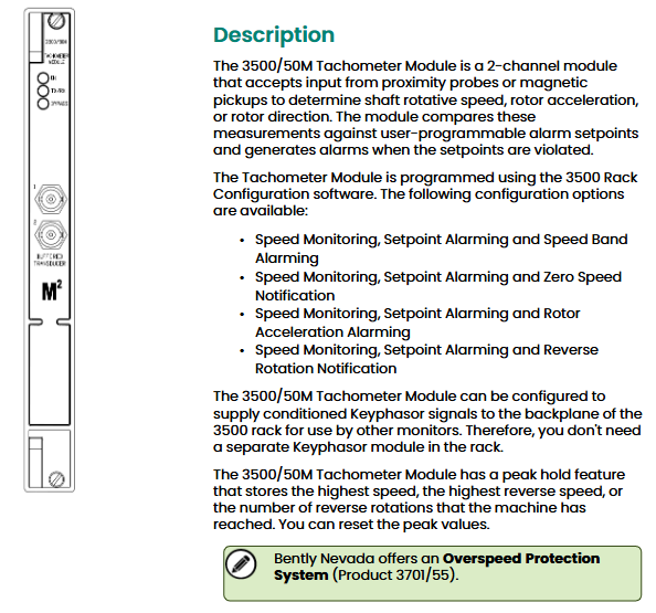
The Approximately Nevada 3500/50M tachometer module is a dual channel module designed specifically for mechanical equipment condition monitoring. It can receive signals from proximity probes or magneto electric sensors, enabling real-time monitoring of shaft speed, rotor acceleration, and rotation direction. It triggers alarms through programmable alarm thresholds and is widely used in rotating machinery such as industrial turbines, generators, and compressors. It also supports providing conditioned Keyphasor signals to the 3500 rack backplane without the need for additional Keyphasor modules.
Core functions and positioning
1. Core monitoring capability
The module supports four types of monitoring configuration schemes, which can be flexibly selected according to the scenario, covering key parameters such as speed, acceleration, and direction:
Configuration plan, monitoring parameters, applicable scenarios
Option 1: Speed monitoring, threshold alarm, and speed bandwidth alarm for devices that need to monitor the range of speed fluctuations (such as generators)
Scenario 2: Speed monitoring, threshold alarm, and zero speed notification require determining the start/stop status of the equipment (such as compressor start/stop confirmation)
Plan 3: Equipment for speed monitoring, threshold alarm, and rotor acceleration alarm to prevent sudden increase/decrease in speed (such as turbine overspeed acceleration prevention)
Option 4: Speed monitoring, threshold alarm, and reverse rotation notification for devices that prohibit reverse rotation (such as pump type mechanical anti reverse protection)
2. Featured Features
Keyphasor signal sharing: It can be configured to output conditioned Keyphasor signals to the 3500 rack backplane for use by other monitoring modules (such as vibration monitoring modules), reducing the number of modules in the rack.
Peak holding: Automatically stores the highest forward speed, highest reverse speed, and number of reversals during device operation. The peak can be manually reset for easy fault tracing.
Flexible alarm configuration: Supports two-level alarms (Alarm 1/Alarm 2), and the alarm threshold and delay time can be set by software to avoid false alarms (such as short-term speed fluctuations not triggering alarms).
Technical parameters
1. Input parameters
The module is compatible with two types of sensors, and attention should be paid to the usage restrictions of magneto electric sensors (see "Safety Warning"):
Parameters, specifications, and notes
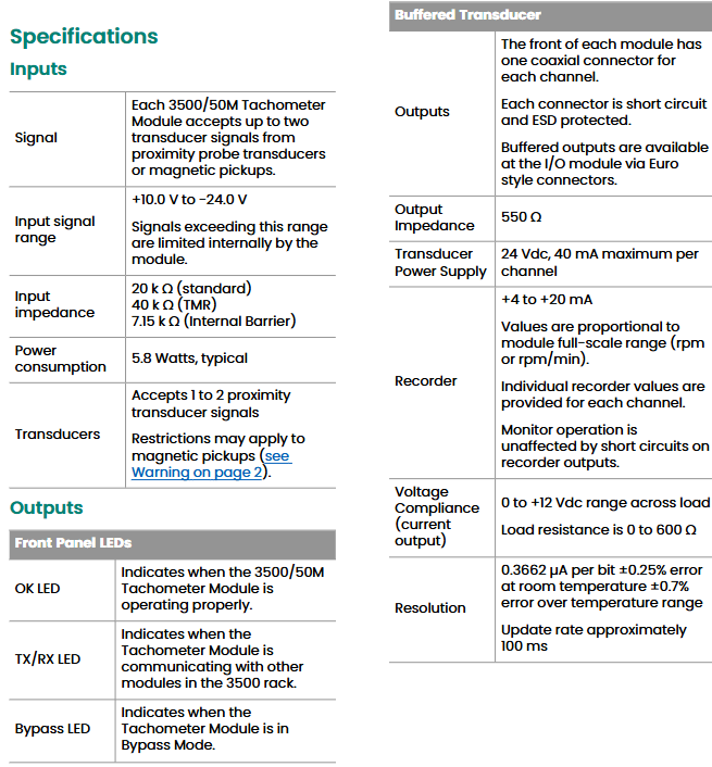
The input signal source is close to the probe (recommended), and the magneto electric sensor does not support reverse monitoring or zero speed monitoring (the signal edge is unclear at low speeds, making it easy to misjudge)
The input signal range is+10.0V~-24.0V. If the signal exceeds the range, it is limited internally by the module to avoid damage
Input impedance standard: 20k Ω; TMR (Triple Modular Redundancy): 40k Ω; Built in isolation barrier: 7.15k Ω, suitable for different system requirements with different configurations
Minimum input frequency close to the probe: 0.0167Hz (1rpm, 1 pulse/rev); Magnetic electric sensor: 3.3Hz magnetic electric sensor does not support low-speed monitoring
The maximum input frequency of 20kHz corresponds to a maximum speed of 99999rpm (matching the number of pulses per revolution)
Number of pulses per revolution, rotor acceleration/zero speed channel: 1-255 pulses per revolution; Other channels: 0.0039~255 pulses per revolution, suitable for speed measuring gears with different numbers of teeth
2. Output parameters
Covering status indication, signal buffering, recording output, etc., to meet monitoring and data recording requirements:
Output type, specification, and function
Front panel LED OK (normal operation), TX/RX (rack communication), Bypass (bypass mode) intuitively judge the working status of the module
Buffer sensor output with 1 coaxial connector per channel (short circuit, ESD protection) for sensor signal multiplexing (such as simultaneous access to oscilloscope debugging)
The sensor power supply is 24VDC, with a maximum of 40mA per channel to provide power for the proximity probe
The recorder outputs a current signal proportional to the full range, with a resolution of 0.3662 µ A/bit, used for data recording and trend chart drawing. Short circuits do not affect module operation
Current output voltage range 0~+12VDC, load resistance 0~600 Ω, suitable for most industrial recorders
Output update rate of approximately 100ms to ensure real-time performance while avoiding data redundancy
3. Accuracy and alarm parameters
Parameters and specifications
Speed accuracy<100rpm: ± 0.1rpm; 100~10,000rpm:±1rpm; 10000~999999rpm: ± 0.01% true speed
Acceleration accuracy ± 20rpm/min
Alarm threshold range 0~100% full scale (software adjustable)
Alarm delay Alarm 1:1~60 seconds (1-second step); Alarm 2:1~60 seconds (0.1 second step size)
Alarm hysteresis 0.2~2.5V (user selectable to prevent frequent switching of alarms)
4. Physical and power consumption parameters
Module type, size (height x width x depth), weight, rack occupancy
Main monitoring module 241.3mm × 24.4mm × 241.8mm (9.50in × 0.96in × 9.52in) 0.82kg (1.8lb) 1 full height front slot
Non barrier I/O module 241.3mm × 24.4mm × 99.1mm (9.50in × 0.96in × 3.90in) 0.20kg (0.44lb) 1 full height rear slot
I/O module with isolation barrier 241.3mm × 24.4mm × 163.1mm (9.50in × 0.96in × 6.42in) 0.46kg (1.01lb) 1 full height rear slot
Typical power consumption is 5.8W --
Safety Warning and Compliance Certification
1. Critical safety warnings
Prohibited as an overspeed protection system: The module does not have redundant protection and sufficient response speed, and cannot be used alone or as a component for speed control systems or overspeed protection systems (such as turbine overspeed shutdown); Analog output is only used for data recording, plotting, or display, and alarms are only used for alarm notification and do not have safety interlock function.
Limitations of magnetic electric sensors: Magnetic electric sensors cannot be used for reverse rotation monitoring and zero speed monitoring. At low speeds, the sensor output signal has no clear edges, which can cause misjudgment of the rotation direction.
Installation in hazardous areas: I/O modules with isolation barriers must be installed according to the specified drawings (138547, 149243/149244) to ensure compliance with hazardous area certification requirements and avoid safety risks.
2. Compliance certification
The module complies with multiple international standards and is suitable for industrial scenarios in different regions around the world
Certification category, compliance standards/directives, scope of application
EMC (Electromagnetic Compatibility) EU EMC Directive 2014/30/EU; EN 61000-6-2 (Industrial Immunity), EN 61000-6-4 (Industrial Emissions) European and globally recognized EMC standards regions
Electrical Safety EU Low Voltage Directive 2014/35/EU; EN 61010-1 Electrical Safety Requirements for Industrial Environments
Environmental Protection EU RoHS Directive 2011/65/EU restricts the use of hazardous substances
Maritime certification DNV GL classification society rules (ships, offshore platforms); ABS Classification Society Rules (Steel Ships, Marine Structures) for Maritime Ships, Marine Platform Equipment
Hazardous Area Certification cNRTLus: Class I, Division 2 (Groups A-D, T4); ATEX/IECEx: II 3G (Ex nA nC ic IIC T4 Gc) explosive environment (such as petrochemical workshops)

Configuration and ordering information
1. Configuration requirements
The specified version of firmware and software must be used to ensure compatibility between the module and the 3500 system
Firmware/software, minimum version, remarks
3500/50M module firmware Revision 5.30 module core firmware determines functional availability
3500/22M module firmware Revision 1.70 firmware for rack communication
3500/01 configuration software Version 4.20 is used for module parameter configuration (such as alarm threshold, sensor type)
3500/02 Data Collection Software Version 2.52 is used to collect module monitoring data
3500/03 Display Software Version 1.52 is used for local or remote display of monitoring data and alarms
Incompatible module 3500/20 (all versions) cannot be shared with 3500/20 module in the same rack
2. Ordering models and accessories
(1) Module model (3500/50-AA-BB)
AA (I/O module type): 01=I/O module with internal terminals; 02=I/O module with external terminal; 04=I/O module with built-in isolation barrier and internal terminals.
BB (hazardous area certification): 00=no certification; 01=cNRTLus certification (Class I, Division 2); 02=ATEX/IECEx/CSA certification (Class I, Zone 2).
(2) Key accessories
Accessory type, model, description
External terminal block (ET Block) 125808-05 tachometer ET block (European connector)
128015-05 Tachometer ET Block (Terminal Block Connector)
128702-01 Recorder ET Block (European connector)
128710-01 Recorder ET Block (Terminal Block Connector)
Signal cable 135101-AAAA-BB tachometer signal to ET block cable (AAAA=length: 0005=5 feet/1.5 meters, 0010=10 feet/3.0 meters, etc.); BB=assembly status: 01=not assembled, 02=assembled)
129529-AAAA-BB recorder output to ET block cable (same specifications as signal cable)
Spare part 288062-02 3500/50M module complete machine
133442-01 I/O module with internal terminal
136703-01 Discrete I/O Module with Built in Isolation Barrier and Internal Termination
134938 3500/50M User Guide
Installation and usage precautions
Sensor selection: Reverse monitoring and zero speed monitoring must use proximity probes, and the use of magneto electric sensors is prohibited; During installation, ensure that the clearance between the proximity probe and the speed measuring gear meets the requirements (usually 0.25-1.0mm) to avoid weak or distorted signals.
Wiring specifications: I/O modules with external terminals require separate ordering of external terminal blocks and cables; Different types of I/O modules cannot be mixed (for example, internal and external terminal modules cannot be shared on the same channel).
Installation in hazardous areas: Modules with isolation barriers must be wired according to specified drawings (such as 138547) to ensure effective isolation barriers and avoid safety risks in explosive environments.
Peak reset: After equipment maintenance, it is necessary to manually reset the peak value to maintain data and avoid the influence of old peak values on fault diagnosis.
Software configuration: For the first use, the 3500/01 configuration software needs to be used to set parameters such as the number of pulses per revolution, alarm threshold, delay time, etc., to ensure that they match the actual operating parameters of the equipment (such as the number of teeth on the speed measuring gear).

- YOKOGAWA
- Reliance
- ADVANCED
- SEW
- ProSoft
- WATLOW
- Kongsberg
- FANUC
- VSD
- DCS
- PLC
- man-machine
- Covid-19
- Energy and Gender
- Energy Access
- Renewable Integration
- Energy Subsidies
- Energy and Water
- Net zero emission
- Energy Security
- Critical Minerals
- A-B
- petroleum
- Mine scale
- Sewage treatment
- cement
- architecture
- Industrial information
- New energy
- Automobile market
- electricity
- Construction site
- HIMA
- ABB
- Rockwell
- Schneider Modicon
- Siemens
- xYCOM
- Yaskawa
- Woodward
- BOSCH Rexroth
- MOOG
- General Electric
- American NI
- Rolls-Royce
- CTI
- Honeywell
- EMERSON
- MAN
- GE
- TRICONEX
- Control Wave
- ALSTOM
- AMAT
- STUDER
- KONGSBERG
- MOTOROLA
- DANAHER MOTION
- Bentley
- Galil
- EATON
- MOLEX
- Triconex
- DEIF
- B&W
- ZYGO
- Aerotech
- DANFOSS
- KOLLMORGEN
- Beijer
- Endress+Hauser
- schneider
- Foxboro
- KB
- REXROTH
- YAMAHA
- Johnson
- Westinghouse
- WAGO
- TOSHIBA
- TEKTRONIX
- BENDER
- BMCM
- SMC
- HITACHI
- HIRSCHMANN
- XP POWER
- Baldor
- Meggitt
- SHINKAWA
- Other Brands
- UniOP
- KUKA
- IBA
- Beckhoff
- ADLINK
-
ADLINK HPCI-14S12U - Industrial Control Backplane 12PCI Backplane PCI-14S Passive Backplane
-
ADLINK PCIe-GIE74C - image acquisition card 4-CH GigE Vision PoE+ Frame Grabber
-
ADLINK PCI-8164 - control card 4-Axis Advanced Motion Controller Board
-
ADLINK PCIe-U304 - 4 Port USB3 PCIe Frame Grabbers USB Screw Hole Card
-
ADLINK PCI-9112 - Multi-Function Data Acquisition Card DAQ Card
-
ADLINK PCI-7432 - 51-12013-0A50 4-CH Isolated Numérique I/O PCI Cartes Digital I/O Card
-
ADLINK PCA-6106P3-0C1 REV.C1 - backplane 6-Slot Passive Backplane Board
-
ADLINK PCI-7224 - 24-CH Opto-Isolated Digital I/O PCI Board
-
ADLINK CPCI-7433R(G) - Digital Input Board Rear I/O CompactPCI Card
-
ADLINK EBP-13E4 - 51-46703-0A30 Industrial PC Backplane Passive Backplane
-
ADLINK PCIE-HDV62 - Image acquisition card High Definition Video Frame Grabber
-
ADLINK EBP-13E4 - 51-46703-0A30 Industrial Backplane Board Passive Backplane
-
ADLINK 90111-B1 / CPCI-6770 - PCB CPU MODULE CompactPCI Single Board Computer
-
ADLINK PCI-7248 - DATA ACQUISITION PCI CARD 48-CH Parallel Digital I/O Board
-
ADLINK PCI-7230 - 51-12003-0a50 board PCI7230 32-CH Isolated Digital I/O Card
-
ADLINK PCI2A000CB - 51-20000-0B30 Multi-Function DAQ Card Baseboard
-
ADLINK PCI-8134-005 - 4-Axis Motion Controller Card
-
ADLINK PCI-7224 - 24-CH Opto-Isolated Digital I/O PCI Card
-
ADLINK PCI-7434 - 64-CH Isolated Digital Output Card
-
ADLINK PCI-8132 - motion control card 2-Axis Servo & Stepper Controller
-
ADLINK PCI-8134 - Motion Controller PCI Card 4-Axis Controller Board
-
ADLINK PCI-8164 - Motion Control Card 51-12406-0A40 4-Axis Controller
-
ADLINK 51-12001-0C20 - Circuit Board Data Acquisition Interface Module Hardware
-
ADLINK NuPR0-840 - industrial control motherboard Full-Size PICMG CPU Board
-
ADLINK PCI-7444 - 51-12023-0A10 card 128-CH Isolated Digital Output Board
-
ADLINK PCI-1612B - data acquisition card 4-Port RS-232/422/485 Serial Communication Card
-
ADLINK PCI-6208V 009 - 8/16-CH 16-Bit Analog Output Cards PCB-I-E-482=6BX3
-
ADLINK NUPRO-935A/LV - industrial control motherboard Full-Size PICMG SBC Board
-
ADLINK PCI-9114DG - Multi-Function DAQ Card Data Acquisition PCI Card
-
ADLINK ACL-7130 - Data acquisition card Isolated Digital I/O Board
-
ADLINK ABX-6300D-4E1-BP - board ABX6300D4E1BP Video Interface Expansion Card
-
ADLINK CPCI-6940 - CPCI-6940/D1539/M16-0(EA)-000E 6U CompactPCI Processor Board
-
ADLINK NuPRO-760 - industrial control motherboard Half-Size PICMG SBC CPU Board
-
ADLINK IMB-M42H (G)-0020 - industrial control motherboard LGA1155 Micro-ATX Mainboard
-
ADLINK RTV-24 / PCI-MP4S - 51-12519-1C30 4-Channel Real Time Video Capture Board
-
ADLINK PCI-8134 - 4-Axis Servo & Stepper Motion Controller Card
-
ADLINK MXC-6101D - V.PC000.002.ST.00 Box PC Configurable Embedded Computer
-
ADLINK PCI-8134A - 51-12421-0A10 Motion Control Card 4-Axis Controller Card
-
ADLINK DIN-100S / DIN-100SA1 - Technology SCSI-II TB 100-PIN Terminal Block Board
-
ADLINK DIN-812M001 / DIN812M001 - 51-14034-0A1 51140340A1 Terminal Module Breakout Interface
-
ADLINK PCI-8164 - Servo motion control 4-Axis Advanced Controller Card
-
ADLINK PCIe-GIE64 - Acquisition card GigE Vision PoE+ Frame Grabber
-
ADLINK M-302 - Industrial control motherboard ATX PC Board Mainboard
-
ADLINK PCI-8134 - Motion Controller PCI Card 4-Axis Controller Board
-
ADLINK PCI-RTV24 - Image capture card Analog Video Frame Grabber
-
ADLINK PCI-8102 - Motion control card 2-Axis Servo & Stepper Controller Board
-
ADLINK PCI-9112 REV.B1 - Card Multi-Function Data Acquisition Card
-
ADLINK HSI-DI32-M-N / HSL-TB32-M-DIN - Discrete I/O MODULE Distributed Automation Module System
-
ADLINK PCI-7296 - IO card REV.A3 96-CH Parallel Digital I/O Card
-
ADLINK DIN-814P-A4 / 814Y - terminal board Motion Control Interface Block
-
ADLINK DIN-814P-A4 - 51-14056-0A10 PCB-I-E-2736=ZA01 Screw Terminal Board Breakout
-
ADLINK M-322 - motherboard Industrial Control Computer Mainboard
-
ADLINK NUPRO-406 REV:B1 - industrial control motherboard Full-Size PICMG CPU Board
-
ADLINK AMP-204C - card DSP-Based 4-Axis Advanced Pulse-Train Controller
-
ADLINK HPCI14S REV.B1 - industrial computer baseboard 14-Slot Passive Backplane
-
ADLINK PCI-7250 - 8-CH Relay Output & 8-CH Isolated DI PCI Card
-
ADLINK EBP-13E2 - baseplate Passive Backplane Industrial Computer Chassis Board
-
ADLINK LPCI-3488A - PCI-GPIB card 51-12801-0A30 acquisition card IEEE-488 Interface Board
-
ADLINK PCI-6216V-GL - 51-12201-0C30 16-CH 16-Bit Voltage Analog Output Card
-
ADLINK ACL-8454 - 16-CH Isolated Digital I/O & 4-CH Counter Card
-
ADLINK HPCI-9S7U - backplane Passive Backplane Compatible with NuPRO-A301 852 841 842
-
ADLINK DAQ-2010-007 - Simultaneous-Sampling Multi-Function Data Acquisition Card
-
ADLINK MP-C154 - 51-64205-0A10 Motion Control Card 4-Axis Controller Board
-
ADLINK MXE-202/mSSD16B/WiFi-BT - Matrix Rugged I/O Platform Embedded Fanless Computer
-
ADLINK CM-920-R-17 - PC/104-Plus Single Board Computer Module Intel Celeron M
-
ADLINK PCI-7250 NSMP - 8-CH Relay Output & 8-CH Isolated DI Card
-
ADLINK PCI-8164 - 4-Axis Motion Controller PCI Card W/ Cable and Breakout Box
-
ADLINK EMX-100 - Ethernet-based 4-axis Motion Controllers Distributed Motion Module
-
ADLINK PCI-8134A - Press control card 4-Axis Motion Controller Board
-
ADLINK M-845EG REV:3.2 - industrial motherboard Pentium 4 Socket 478 Micro-ATX
-
ADLINK PCI-9114A Rev A2 DG - card High-Resolution Multi-Function Data Acquisition Board
-
ADLINK IEC-915GV - REV 1.1 Industrial motherboard Socket 478 CPU Board
-
ADLINK PCI-9111DG(G) - Data Acquisition Card Multi-Function DAQ Card
-
ADLINK HPCI-15S10 REV:B2 - Industrial computer base plate Passive Backplane Board
-
ADLINK NuPR0-840 / NuPR0-840DV - industrial control motherboard Full-size PICMG CPU Board
-
ADLINK RTV-24 / PCI-MP4S - 51-12519-1C30 4-Channel Real Time Video Capture Board
-
ADLINK NUPRO-780 - industrial control motherboard Pentium III Single Board Computer
-
ADLINK PCI-7296 - 0050 card 96-CH Opto-Isolated Parallel DIO Card Set
-
ADLINK NUPRO-780 - industrial control motherboard PICMG Full-Size SBC
-
ADLINK PCI-7248 - 51-12006-0A3 002 Pci 7248 48-CH Parallel Digital I/O Card
-
ADLINK PCI-7230 - 32-CH Isolated Digital I/O Card
-
ADLINK AMP-204C - motion control card 4-Axis Advanced Controller Board
-
ADLINK PCI-1714UL - Card Ultra High-Speed 4-CH Simultaneous Sampling DAQ
-
ADLINK NuPRO-E330 - industrial computer equipment motherboard PICMG 1.3 SHB SBC
-
ADLINK AMP-204C - DSP-Based 4-Axis Advanced Pulse-Train Motion Controller Module
-
ADLINK PCI-7256 - 001 51-12206-0A2 REV.A2 LPCI-7256 16-CH Latching Relay Output Card
-
ADLINK ND6050 - NUDAM DIGITAL I/0 MODULE Distributed I/O Unit
-
ASEM BM100 - Box PC Embedded Fanless Industrial Computer
-
ADLINK PCI-7250 - PCI Acquisition Card 8-CH Relay Output & Isolated DI Board
-
ADLINK PCI-8164 - Servo motion control 4-Axis Controller Card
-
ADLINK NuPRO-A40H - Industrial Motherboard 51-41807-1A30 OSP LGA1155 H61
-
ADLINK ADMAX X300 SERVER - 51066010-0A30 motherboard Multi-Processor Mainboard
-
ADLINK CMe-GIE62+ - 51-32903-0A30 control card PC/104-Plus GigE Vision Frame Grabber
-
ADLINK NUPRO-780 - industrial control motherboard Full-Size PICMG SBC CPU Board
-
ADLINK ETX-AT-N270-18/GKTEL - 51-71111-OB10 motherboard ETX CPU Module Board
-
ADLINK DIN-812M - interface module Terminal Block Connection Board
-
ADLINK IMB-M42H - industrial control motherboard LGA1155 Micro-ATX Mainboard
-
ADLINK PXIS-2508 - 8-slot 3U PXI Instrument Chassis Power Hardware Assembly
-
ADLINK AMP-208C - Motion Control card DSP-Based 8-Axis Pulse-Train Controller
-
ADLINK PCI-9111 / PCI-9111DG - Multi-Function Data Acquisition Card DAQ Board
-
ADLINK IEEE-488 GPIB card - Bus Interface Controller Communication Board
-
ADLINK RTV-24 - 51-12519-1C30 image acquisition card Video Frame Grabber Card
-
ADLINK TB-24P/24-01 - Board 24 Way Screw Terminal Breakout Board
-
ADLINK HSL-DI16DO16-DB-NN - 51-23015-0A40 Distributed Discrete I/O Module Set
-
ADLINK PCI-7442 - switch quantity card data acquisition card 64-CH Isolated Card
-
ADLINK ACL-7130 REV. B2 - industrial control capture card Isolated Digital I/O PCI Card
-
ADLINK PCI-6S / PCI6S - Backplane 6-Slot Passive Backplane Chassis Board
-
ADLINK ACL-8113A - card Isolated Digital Input Card
-
ADLINK CPCI-6208V-003 - board cPCI CompactPCI 8-CH Analog Output Card
-
ADLINK DIN-100S-01(G) - SCSI 100-Pin Terminal Block Interface Board
-
ADLINK PCI-7433 - Isolated Digital Input Card 64-CH
-
ADLINK PCI-9812 - Synchronous sampling analog input card High-Speed DAQ Board
-
ADLINK PCI-7434 REV.B1 - PLOTECH PCB-I-E-1182=6EX2 64-CH Isolated Digital Output Card
-
ADLINK PCIe-RTV24 - 51-18016-0A20 4-CH Real-Time Video Capture Card PCIe Frame Grabber
-
ADLINK PCI-8144 / PCI-8144N - Motion control card 4-Axis Stepper Motor Controller
-
ADLINK DIN-68S-01 - terminal board 68-Pin Connector Terminal Block
-
ADLINK MP-C154 - Motion control card 4-Axis Advanced Controller Card
-
ADLINK PCI-7248 (G) - Motherboard 48-CH Parallel Digital I/O Card
-
ADLINK MXE-1301(G) - Intel Atom D2550+NM10 MXE 1300 Series 93-4130-0030 Embedded Computer
-
ADLINK PRO-841 Rev 2.0 / PRO-060907000670 - CPU 2.26GHz & RAM Industrial PC Board
-
ADLINK cPCI-6626 - 6U CompactPCI 2.0 Blades i7-2710QE PCB-I-E-2570=9N41
-
ADLINK MXC-6322D(G) - Industrial Fanless Computer
-
ADLINK cPCI-8168-004 - CompactPci NulPC Motion Control Board 51-36402-0A3
-
ADLINK CPCI-7300[G] - COMPACTPCI Digital I/O Card Data Acquisition
-
ADLINK CPCI-6626/2710/M4G - COMPACTPCI COMPUTER BOARD
-
ADLINK cPCI-8168-009 - cPCI NulPC Motion Control Board
-
ADLINK cPCI-6626/2710/M4G - VME CPU Board Computer Board
-
ADLINK CPCI-R6200(G)-0040 - COMPACTPCI CONTROL BOARD

K-JIANG

Add: Jimei North Road, Jimei District, Xiamen, Fujian, China
Tell:+86-15305925923