
K-WANG


Westinghouse 2400i digital inverter generator
Power parameters: displacement of 79cm ³, maximum speed of 5000rpm, intelligent adjustment of speed with load (operating at the lowest speed in ECO mode)
Westinghouse 2400i digital inverter generator
Detailed explanation of core product information
1. In depth analysis of technical parameters
Category parameter details note explanation
The engine system has a single cylinder four stroke overhead valve (OHV), and the air-cooled OHV design improves combustion efficiency and extends engine life; Air cooled structure simplifies maintenance and adapts to complex outdoor environments
Power parameters: displacement of 79cm ³, maximum speed of 5000rpm, intelligent adjustment of speed with load (operating at the lowest speed in ECO mode)
Oil specification: The oil capacity is 400mL. It is recommended to use SAE 15W-40 API SG grade for ambient temperatures greater than 40 ℃, and 10W-30 for temperatures ≤ 40 ℃; It is strictly prohibited to mix different types of engine oil
Unleaded gasoline (91 octane and above) for the fuel system, with an ethanol content of ≤ 10%. If the ethanol content in the 5.0L fuel tank is too high, it is easy to cause corrosion of the fuel system. It is recommended to prioritize the use of ethanol free gasoline; Under full fuel condition, ECO mode can run for 8-10 hours
AC output 240V/50Hz, continuous power 2100W, starting power 2400W pure sine wave output, total harmonic distortion<3%, suitable for sensitive equipment such as computers and precision instruments
DC output 12V, maximum current 8A, maximum power 100W. The output is non regulated to avoid connecting devices that are sensitive to voltage fluctuations (such as precision electronic devices)
The protection level of the socket is IP44, which can resist splashing water but cannot be exposed to rain or soaking
Physical characteristics: length 500mm x width 340mm x height 440mm, dry weight 20kg. The handle design is convenient for single person short distance transportation, and the wet weight includes the weight of engine oil and fuel
2. Complete analysis of control panel functions
Component Name Function Description Operation Points
240V AC 15A socket (2 sockets) outputs 240V AC power, with a maximum load of 2400W per socket. When inserting the plug, it needs to be fully pushed in and the waterproof cover should be closed after use
Press and hold the engine stop button to stop the engine. In emergency situations, it can be used directly. Normal shutdown requires disconnecting the load first and running without load for 1 minute before operation
After the reset button of the generator is overloaded or short circuited, after troubleshooting, it is necessary to ensure that the load does not exceed the standard before resetting the AC output, otherwise the protection will be triggered again
ECO throttle switch ON: energy-saving mode, OFF: standard mode. ECO mode is used for small loads (<1000W), and standard mode is used for large loads (>1500W) or inductive loads
Throttle knob START (cold start), RUN (hot run) After starting the cold engine, preheat the engine for 3-5 minutes before pushing it to the RUN position to avoid stuffiness
Multi functional VST instrument displays voltage, speed, and cumulative running time. Press the panel button to switch display modes, and the backlight can be illuminated in low light environments
Fuel control switch ON (run), OFF (stop) should be turned to OFF for long-term storage, and the machine should be stopped after running out of fuel
The low oil warning light (red) lights up when the oil level is too low, and the engine automatically shuts down. It needs to be refilled with oil to the standard level before restarting
Overload alarm light (red) lights up when the load exceeds the standard or short circuit occurs. To cut off the AC output, the load needs to be reduced or the short circuit fault needs to be eliminated before resetting
Output indicator light (green) lights up when the engine is running and the AC output is normal. The green light does not light up but the engine is running. It is necessary to troubleshoot the output fault
Connect the grounding terminal to the ground wire to enhance electrical safety. It is recommended to ground when outdoors in humid environments or when connecting metal enclosed equipment
12V DC socket outputs 12V DC power, compatible with cigarette lighter plug. Do not insert into car cigarette lighter (high temperature can easily cause fire)
3. Function and position of core components
Air filter: located on the right side of the body, filters dust from the intake air to prevent engine cylinder wear; Regular cleaning is required, and the cycle should be shortened in dusty environments.
Spark plug: located on the left side of the body, it generates an electric spark to ignite the fuel mixture; Carbon deposition or wear can cause difficulty in starting and unstable operation.
Spark arrester: installed at the outlet of the muffler to prevent sparks from escaping and causing fires; When used in outdoor or dry environments, it is necessary to ensure cleanliness and smoothness.
Fuel filter: located below the fuel inlet inside the fuel tank, filters impurities in the fuel to avoid clogging the fuel injectors.
Oil inspection cover: on the left side of the body, open to check or add oil; The oil filling port is threaded, so avoid over tightening and damaging the threads when tightening.
Fuel emission hose: located at the bottom of the left side of the aircraft, used to drain the fuel from the tank (such as during long-term storage or when the fuel deteriorates).

Safety operation rules (including risk avoidance)
1. Environmental safety requirements
The operating position should meet the following requirements: good outdoor ventilation, away from doors, windows, ventilation openings, tents, etc. (to prevent the accumulation of carbon monoxide); The ground is flat and hard (to avoid vibration and tilting during operation, which may cause fuel/oil leakage); Maintain a distance of at least 1.8m from combustible materials such as wood, hay, paint, etc., and maintain a heat dissipation space of at least 0.5m from other equipment.
Prohibited from use in the following scenarios: confined spaces (indoor, garage, basement), damp ground (waterlogged, muddy), thunderstorm weather, and high dust concentration environments (such as construction site dust areas).
Extreme environmental response: When operating at high temperatures (>35 ℃), it is necessary to operate in a cool place and avoid direct sunlight; When the temperature is low (<0 ℃), winter specific engine oil (such as 5W-30) should be used, and the engine block can be preheated before starting (to avoid open flame heating).
2. Fuel safety operation
Preparation before refueling: Turn off the engine and wait for at least 10 minutes for it to cool down (the muffler temperature can reach over 400 ℃, which can easily ignite the fuel); Clean the oil around the fuel filler to prevent impurities from entering the fuel tank.
Refueling operation: Use a dedicated refueling pot to slowly refuel, with the oil level not exceeding the red limit ring in the fuel tank (reserve 5-10% expansion space); If fuel spills, immediately wipe it clean with a dry cloth and wait for it to evaporate before starting the engine.
Fuel storage: Backup fuel should be stored in a qualified fuel container, in a ventilated, cool, and away from sources of fire, for a period of no more than 3 months (with the addition of fuel stabilizers, it can be extended to 6 months).
Forbidden operation: Do not refuel while the engine is running; Prohibit using fuel to clean equipment; Do not place fuel containers on the generator or near heat sources.
3. Electricity safety regulations
Extension cable selection: 240V AC extension cables must comply with AS/NZS 3199:2007 standards, using 15A heavy-duty three core cables (core cross-sectional area ≥ 1.5mm ²), with a length not exceeding 25m (1.5mm ²) or 40m (2.5mm ²); The length of the 12V DC extension cable shall not exceed 3.5m, and the cross-sectional area of the wire core shall be ≥ 1.0mm ².
Load calculation method:
Pure resistance load (light bulb, heater, rice cooker): starting power=operating power, total operating power ≤ 2100W.
Inductive loads (air conditioning, water pump, motor): starting power=operating power x 1.2 (small portable equipment) or 3.5 (large fixed equipment), total starting power ≤ 2400W.
Example: 1.5kW air conditioner (operating power 1500W), starting power=1500 × 3.5=5250W>2400W, cannot be driven separately; 0.8kW water pump (operating power 800W), starting power=800 × 1.2=960W, can be driven.
Grounding requirements: The generator itself has an equipotential connection system and does not require separate grounding; If connecting fixed equipment or using in humid environments, a certified electrician must connect the grounding terminal to the grounding electrode (such as a metal grounding rod).
Emergency response: In case of equipment tripping, heating, or odor during power consumption, immediately disconnect the load, shut down the generator, and troubleshoot before use.
4. Personnel safety protection
Wear goggles (to prevent fuel splashes and debris from entering the eyes) and gloves (to prevent oil contamination and burns) during operation; Long hair should be curled up to avoid getting caught up in moving parts.
Children and pets are prohibited from entering within a 1m radius of the generator; Operators need to be familiar with the operating procedures and avoid operating under the influence of alcohol or fatigue.
Emergency situation handling: In case of fuel leakage, immediately stop operation, stay away from the scene, and clean up after the fuel evaporates; If a fire occurs, use ABE or BE type fire extinguishers to extinguish it (it is prohibited to directly extinguish electrical fires with water); If you feel dizzy or nauseous after inhaling carbon monoxide, immediately transfer to a well ventilated area and seek medical attention in severe cases.
Step by step operation guide (including key details)
1. Preparation for the first use of the new machine
Open the box inspection: Open the packaging and take out the generator and accessories (400mL SAE 15W-40 engine oil, fuel can, screwdriver, spark plug socket wrench, dust cover, instruction manual); Check that the appearance of the generator is undamaged, the components are not loose, and the sockets and switches are functioning properly.
Oil filling:
Place the generator on a level surface and open the left oil maintenance cover.
Clean the area around the oil filling port with a clean cloth to prevent impurities from entering.
Using the included fuel can, slowly add oil to the bottom edge of the filling port (the oil level should be level with the filling port and not overflow).
Tighten the oil filling plug, close the maintenance cover, and wipe off any remaining oil.
Fuel filling:
Unscrew the fuel cap (counterclockwise) and clean the area around the fuel port.
Add unleaded gasoline of grade 91 or above, with the fuel level not exceeding the red limit ring inside the fuel tank.
Tighten the fuel cap (clockwise), turn the fuel cap vent to the ON position, and check for fuel leaks.
2. Start up process (including differences in cooling/heating)
Step operation content: Key points for starting a cold machine, key points for starting a hot machine
1. Environmental and status confirmation: Outdoor ventilation, flat and dry ground, disconnect all loads and start the refrigeration unit
2. Prepare the fuel system and turn the fuel control switch to ON. Turn the fuel cap vent to ON and start the cooling machine
Adjust the air damper to the START position (fully pulled out) and keep it in the RUN position (pushed in)
4. Start operation: Hold down the generator body with one hand (to prevent vibration displacement), and hold the recoil start handle with the other hand. Slowly pull until you feel an increase in resistance (piston compression stroke), then quickly and forcefully pull the handle. After starting, slowly release it back (to avoid the handle rebounding and hitting the body). The pulling resistance is small and does not require excessive force. Keep running directly after starting
After preheating and adjusting the engine, let it idle for 3-5 minutes, gradually push the throttle to the RUN position, and observe that the instrument voltage stabilizes at around 240V without prolonged preheating. After starting, connect a light load
3. Operation and monitoring during operation
Load connection:
Confirm that the generator is running stably and the output indicator light (green) is on.
240V equipment: directly plugged into an AC socket or connected through a qualified extension cord; Ensure that the plug is fully in contact during insertion to avoid loosening and overheating.
12V device: Insert the cigarette lighter plug into the DC socket, ensuring that the plug is securely fastened; The total power shall not exceed 100W.
Operation monitoring:
Real time monitoring of instruments: The voltage should be stable between 230-250V, and the speed should vary with the load (in ECO mode, the lower the load, the lower the speed).
Monitor engine sound: During normal operation, the sound is uniform and there is no abnormal noise (such as knocking or whistling); If there is any abnormal noise, stop the machine immediately for inspection.
Check the indicator lights: both the low fuel alarm light and the overload alarm light should be turned off; If it lights up, follow the troubleshooting process.
load regulation:
To avoid sudden connection of high-power loads (such as air conditioning and water pumps), the load switch should be turned off first, and then gradually turned on after connection.
When multiple devices are used simultaneously, connect the low-power device first and then the high-power device to ensure that the total starting power does not exceed 2400W.
If there is an overload alarm (red light on), immediately disconnect part of the load, wait for 30 seconds, press the reset button, and then reconnect.
4. Shutdown process (including different scenarios)
Precautions for operating steps in shutdown scenarios
Normal shutdown: 1. Disconnect all loads (unplug or turn off the device switch); 2. Run the generator without load for 1 minute (cool down the engine and generator); 3. Press and hold the engine stop button until the engine is completely stopped; 4. Turn the fuel control switch to OFF; 5. Turn the fuel cap vent to OFF; 6. Close all waterproof covers of sockets and cover them with dust covers (if not used for a long time). Do not stop the machine directly, otherwise it may cause carbon buildup in the engine and overheating of the generator
Emergency shutdown (such as fire or leakage): Press and hold the engine stop button until the machine stops; Follow the normal process to check for faults and use them again after troubleshooting. Only for emergency situations, frequent emergency shutdowns may affect the lifespan of the equipment
Long term shutdown (over 1 week): 1. Disconnect all loads and run without load for 1 minute; 2. Turn the fuel control switch to OFF and allow the engine to continue running until the fuel runs out and automatically shuts down; 3. Close the fuel cap vent; 4. Drain the engine oil (if not used for more than 3 months); 5. Clean the surface of the generator and cover it with a dust cover to prevent fuel from deteriorating and blocking the oil circuit, thus extending the storage life
5. Two methods for charging 12V batteries (including safety points)
Method 1: Direct charging from DC socket (emergency use)
Tool preparation: 12V DC charging cable (with cigarette lighter plug and crocodile clip, rated current ≥ 8A), battery to be charged (12V lead-acid battery).
Operation steps:
Start the generator according to the normal procedure and turn off the ECO mode after stable operation.
Clean the positive and negative terminals of the battery and remove oxides (gently rub with sandpaper).
Connect the crocodile clip of the charging cable to the battery: the red clip is connected to the positive pole (+), and the black clip is connected to the negative pole (-), ensuring clamping (to avoid poor contact and heat generation).
Insert the cigarette lighter plug of the charging cable into the 12V DC socket of the generator.
During the charging process, maintain a distance of at least 1m between the battery and the generator (to prevent hydrogen explosions during battery charging), monitor the battery temperature in real-time, and immediately stop charging if the battery is hot or the electrolyte boils.
Charging time: adjusted according to battery capacity, generally not exceeding 3 hours; When there is no monitoring tool, disconnect after charging for 2 hours and test the battery voltage (full charge voltage is about 12.6V).
Charging completed: First unplug the cigarette lighter plug, then disconnect the crocodile clip (negative first, positive later), and cover the battery vent caps.
Method 2: Charging the AC socket through a charger (recommended)
Tool preparation: A 12V battery charger with 240V AC input (compatible with battery types such as lead-acid and lithium batteries).
Operation steps:
Start the generator and connect the charger power plug to a 240V AC socket after stable operation.
Connect the battery according to the charger manual (positive to positive, negative to negative).
Turn on the charger and set the appropriate charging mode (such as constant voltage, constant current).
During the charging process, monitor the charger indicator light and battery temperature, and complete the charging according to the charger prompts.
Charging completed: Turn off the charger, unplug the power plug, disconnect the battery connection, and stop the generator.
Advantages: The charger can intelligently adjust the charging current and voltage, avoiding overcharging and damaging the battery, and has higher safety.
Complete maintenance process (including cycle and operation details)
1. Preparation before maintenance
Safety measures: Turn off the generator and remove the spark plug cap (to prevent accidental starting); Let the engine cool to room temperature (to avoid scalding of high-temperature components); Operate in a well ventilated area and prepare tools such as cloths, wrenches, containers, etc.
Tool list: Phillips screwdriver, Phillips screwdriver, spark plug socket wrench, oil pan, funnel, wire brush, compressed air (optional), new engine oil, new spark plug (spare).
2. Routine maintenance items (executed on a periodic basis)
Before/after each use
Cleaning: Use a damper cloth to wipe the dust and oil stains on the surface of the generator, and clean the debris from the heat dissipation port and ventilation hole (to avoid blockage that affects heat dissipation).
Check:
Appearance: The components are not loose or damaged, and the socket has no burn marks.
Oil: The oil level is within the standard range and there is no leakage; There is no fuel leakage and the fuel gauge shows sufficient.
Wiring: The wires are not damaged or aged, and the plugs are securely connected.
Every 20 hours (after first use)
Oil change:
Place the generator on a level surface, start the engine and run it for 1 minute (allowing the oil to flow and facilitate drainage), then stop it.
Open the oil inspection cover, clean the area around the filling port, and place the oil basin under the filling port.
Unscrew the oil filler plug, tilt the generator, and allow the old oil to flow completely into the oil pan (about 5 minutes).
Tighten the oil filling plug and add 400mL of new oil (SAE 15W-40 API SG grade) through the funnel.
Tighten the filling plug, start the engine and run it for 1 minute, check if the oil level is normal and if there are any leaks.
Old engine oil treatment: Pour into a sealed container and hand it over to a professional organization for recycling (no dumping at will).
Every 50 hours/3 months
Air filter cleaning:
Unscrew the 6 screws of the air filter maintenance cover on the right side of the body, and remove the maintenance cover and air filter cover (with the central screw).
Take out the foam filter element and pay attention to the position of the bevelled corner (easy to replace).
Clean the filter element with warm water and a small amount of detergent, gently squeeze (without twisting or tearing), and remove dust and oil stains.
Rinse with clean water, squeeze and drain the water, then use a dry cloth to absorb any remaining moisture (or air dry naturally, do not expose to direct sunlight).
Apply a thin layer of engine oil evenly on the surface of the filter element (to enhance the filtering effect), and squeeze to remove excess engine oil.
Reinstall the filter element, filter cover, and maintenance cover in their original positions, and tighten the screws.
Fuel filter inspection:
Unscrew the fuel cap and remove the fuel filter from the fuel tank (pull it out directly by hand).
Pour out the fuel and impurities from the filter, and blow the filter screen from the outside to the inside with compressed air (or rinse with clean gasoline).
Check the filter screen for any damage or blockage, and reinstall it into the fuel tank (ensuring complete insertion).
Every 100 hours/6 months
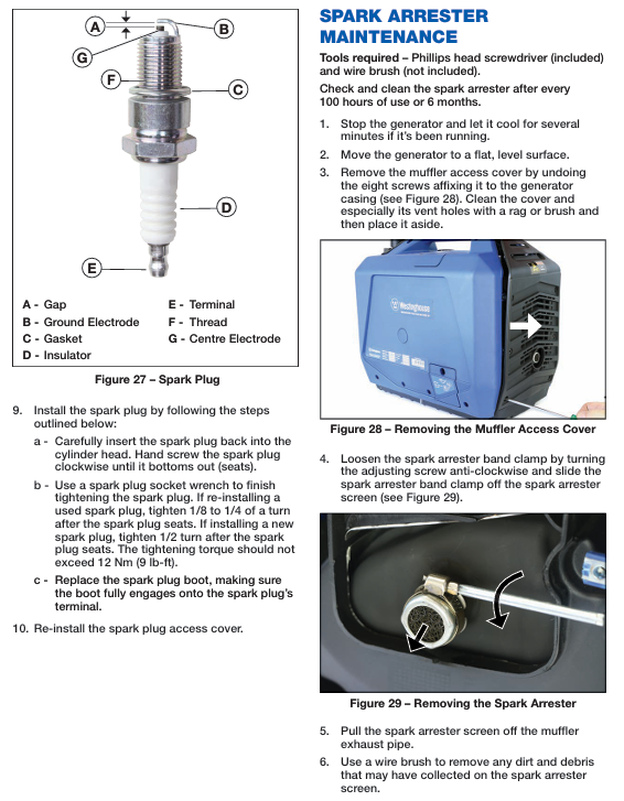
Spark plug cleaning:
Open the spark plug inspection cover on the left side of the body and remove the spark plug cap (pull vertically upwards with force to avoid damage from side pulling).
Clean the dust and oil around the spark plug with a cloth, and use a spark plug socket wrench to unscrew the spark plug counterclockwise.
Check the spark plug: there are no cracks in the insulator and no excessive wear on the electrode; If there is carbon deposition, clean the electrode with a wire brush.
Adjust spark plug gap: Measure with a plug gauge, the gap is 0.6-0.7mm, and adjust by bending the grounding electrode.
Reinstall spark plug: Tighten clockwise by hand until it fits the cylinder head, then use a wrench to tighten (old spark plug by 1/8-1/4 turn, new spark plug by 1/2 turn, torque not exceeding 12Nm).
Insert the spark plug cap back in place, ensuring it is fully engaged, and close the maintenance cover.
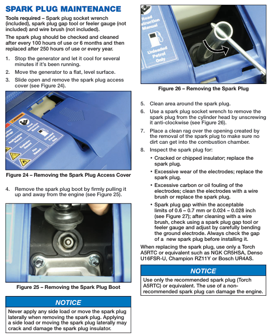
Spark Arrester Cleaning:
Unscrew the 8 screws on the left muffler maintenance cover of the body and remove the maintenance cover.
Loosen the spark arrester clamp screw counterclockwise and remove the clamp and spark arrester filter.
Use a wire brush to remove carbon deposits and debris from the surface of the filter screen. If the filter screen is damaged or has holes, it needs to be replaced.
Reinstall the filter screen and clamp in place, tighten the screws, and reinstall the inspection cover.
Every 250 hours/1 year
Oil change (as before).
Spark plug replacement: Replace with recommended models (Torch A5RTC, NGK CR5HSA, etc.), and check the clearance before installing the new spark plug.
Fuel system cleaning:
Drain the fuel tank, remove the fuel filter, and thoroughly clean it.
Check the fuel pipeline for aging and leaks, and replace it if necessary.
Valve clearance inspection (professional maintenance): Operated by certified technicians or authorized dealers, adjust the valve clearance to the standard range (to avoid damaging the engine by self operation).
3. Long term storage and maintenance (over 3 months)
Preparation before storage:
Clean the surface of the generator, remove dust, oil stains, and debris.
Drain fuel:
Unscrew the fuel cap, remove the fuel filter, and use a siphon pump or directly pour out the fuel from the tank.
Open the fuel emission inspection cover (Phillips screwdriver), loosen the fuel emission screw (Phillips screwdriver), drain the residual fuel in the fuel pipeline, then tighten the emission screw and reinstall the inspection cover.
Reinstall the fuel filter and fuel cap, and close the fuel cap vent.
Oil change: According to the oil change process, drain the old oil and add new oil (400mL).
Anti rust treatment of cylinder:
Remove the spark plug and inject 1 tablespoon of new engine oil into the cylinder.
Pull the recoil starter handle 3-5 times by hand (without inserting the spark plug) to evenly distribute the engine oil on the cylinder wall.
Reinstall the spark plug and pull the starter lever until you feel an increase in resistance (piston in compression stroke, valve closed).
Cover with a dust cover and place in a dry, ventilated, and cool room (do not store in areas with flammable materials).
After storage, remove and use:
Remove the dust cover and check the appearance of the generator for any damage or debris.
Check the oil level of the machine and replenish it if it is insufficient.
Add fresh fuel (do not use fuel that has been stored for too long).
According to the normal start-up process, the engine may emit smoke for a short period of time (residual oil in the cylinder), which is a normal phenomenon and will disappear after running for 1 minute.
4. Maintain taboos and precautions
Do not use flammable solvents such as fuel or banana oil to clean components (such as air filters and machine bodies) to avoid causing fires.
Mixing different brands and models of engine oil is prohibited, and the use of two-stroke engine oil or inferior engine oil is also prohibited.
When replacing spark plugs, the recommended model must be used and the tightening torque should not be too high (to avoid damaging the cylinder head threads).
When cleaning the air filter, do not twist or tear the foam filter element, otherwise the filtering effect will be reduced.
After all maintenance operations, it is necessary to ensure that the components are securely installed and the screws are tightened to avoid detachment during operation.
Deep troubleshooting of common faults (including causes and solutions)
Possible causes of malfunction, troubleshooting steps, and solutions
The engine cannot start. 1. Insufficient oil (low oil protection); 2. Fuel depletion or deterioration; 3. The position of the air damper is incorrect; 4. Spark plug malfunction (carbon buildup, improper clearance, damage); 5. The fuel control switch is not turned on; 6. The fuel cap vent is closed; 7. Air filter blockage 1. Check the oil level of the machine and replenish it to the standard; 2. Check the fuel gauge and add fresh fuel; 3. Confirm the position of the air damper (cold engine START, hot engine RUN); 4. Remove the spark plug and check its condition; 5. Confirm that the fuel control switch is in the ON position; 6. Open the fuel cap vent; 7. Check if the air filter is clogged. 1. Add engine oil; 2. Replace with fresh fuel; 3. Adjust the position of the air damper; 4. Clean spark plugs, adjust clearances, or replace with new spark plugs; 5. Switch the fuel control switch to ON; 6. Unscrew the fuel cap vent; 7. Clean or replace the air filter
Stop the engine immediately after starting. 1. Insufficient engine oil; 2. Fuel pipeline blockage; 3. The air damper has not been adjusted; 4. The load is not disconnected. 1. Check if the low fuel alarm light is on; 2. Check for blockages in the fuel filter and fuel pipelines; 3. Confirm whether the choke is in the RUN position; 4. Check if there is a load connection. 1. Add engine oil; 2. Clean the fuel filter and unclog the pipeline; 3. Adjust the air damper to the RUN position; 4. Disconnect all loads and start with no load
There is engine noise but no AC output. 1. Failure to reset after overload or short circuit; 2. Output indicator light malfunction; 3. Internal malfunction of the generator; 4. Load device failure: 1. Check if the overload alarm light is on and press the reset button; 2. Replace known normal equipment for testing; 3. Turn off the generator and wait for 5 minutes before restarting (ECO mode OFF); 4. If there is still no output, check the inside of the generator. 1. Disconnect the overload load and press the reset button; 2. Replace the load equipment; 3. Restart the generator; 4. Contact authorized dealers for repairs
DC no output 1. Poor socket contact; 2. Load exceeding the standard; 3. DC line fault: 1. Re plug and unplug the DC plug to ensure it is securely fastened; 2. Check if the load power exceeds 100W; 3. Turn off the generator and check if the DC line is damaged. 1. Ensure that the plug is in good contact; 2. Reduce the load to within 100W; 3. Repair or replace the damaged circuit. If the circuit is normal, contact the repair team for assistance
The engine runs unstably and shakes. 1. The fuel deteriorates or contains moisture; 2. The air filter is clogged; 3. Spark plug carbon deposition; 4. Excessive load fluctuations; 5. The throttle valve is dirty. 1. Check the fuel condition and observe whether there is moisture (stratification phenomenon) in the fuel tank; 2. Check the air filter; 3. Clean the spark plug; 4. Check if the load starts and stops frequently; 5. Check if the throttle valve is dirty. 1. Drain the deteriorated fuel and add fresh fuel; 2. Clean the air filter; 3. Clean or replace spark plugs; 4. Stabilize the load and avoid frequent switching; 5. Clean the throttle valve (professional operation)
Abnormal noise during operation: 1. Loose spark plug; 2. Wear and tear of internal engine components; 3. Malfunction of the cooling fan; 4. Loose components 1. Check if the spark plug is tightened; 2. Listen to the source of abnormal noise (cylinder, fan, body); 3. Check if the cooling fan is rotating normally; 4. Check for loose screws and components on the body. 1. Tighten the spark plug; 2. Immediately shut down the machine and contact an authorized dealer for maintenance; 3. Repair or replace the cooling fan; 4. Tighten loose screws and components
Fuel consumption is too fast. 1. ECO mode is not turned on; 2. Excessive load; 3. The engine speed is too high; 4. Fuel leakage: 1. Check if the ECO mode is in the ON position (under low load); 2. Check if the load power is close to the rated power; 3. Observe whether the instrument speed is abnormally high; 4. Check for leaks in the fuel pipeline and fuel tank. 1. Activate ECO mode under low load; 2. Reduce the load and avoid long-term full load operation; 3. Check if the throttle valve is stuck and contact for repair; 4. Repair the leaking area and replenish fuel
- YOKOGAWA
- Reliance
- ADVANCED
- SEW
- ProSoft
- WATLOW
- Kongsberg
- FANUC
- VSD
- DCS
- PLC
- man-machine
- Covid-19
- Energy and Gender
- Energy Access
- Renewable Integration
- Energy Subsidies
- Energy and Water
- Net zero emission
- Energy Security
- Critical Minerals
- A-B
- petroleum
- Mine scale
- Sewage treatment
- cement
- architecture
- Industrial information
- New energy
- Automobile market
- electricity
- Construction site
- HIMA
- ABB
- Rockwell
- Schneider Modicon
- Siemens
- xYCOM
- Yaskawa
- Woodward
- BOSCH Rexroth
- MOOG
- General Electric
- American NI
- Rolls-Royce
- CTI
- Honeywell
- EMERSON
- MAN
- GE
- TRICONEX
- Control Wave
- ALSTOM
- AMAT
- STUDER
- KONGSBERG
- MOTOROLA
- DANAHER MOTION
- Bentley
- Galil
- EATON
- MOLEX
- Triconex
- DEIF
- B&W
- ZYGO
- Aerotech
- DANFOSS
- KOLLMORGEN
- Beijer
- Endress+Hauser
- schneider
- Foxboro
- KB
- REXROTH
- YAMAHA
- Johnson
- Westinghouse
- WAGO
- TOSHIBA
- TEKTRONIX
- BENDER
- BMCM
- SMC
- HITACHI
- HIRSCHMANN
- XP POWER
- Baldor
- Meggitt
- SHINKAWA
- Other Brands
- UniOP
- KUKA
- IBA
-
Woodward 9905-373 - Digital Synchronizer And Load Controller
-
WOODWARD MAGNETIC PICKUPS - Sensor
-
WOODWARD GCP-30 - Steuertafel for Industrial Regulator Genset Control Package
-
WOODWARD GOVERNOR 9907-1183 REV A - 505 ENHANCED TURBINE CONTROL
-
WOODWARD 9907-173 REV B - Module Load Sharing 120 Volt
-
WOODWARD 9907-014 - 2301A controller
-
Woodward 9905-029 - SPM-A Synchronizer Module Rev C
-
WOODWARD 8440-1799 EASYGEN-350 REV B - Genset Controller
-
WOODWARD 5466-258 REV M - SIMPLEX DISCRETE I/O MODULE
-
Woodward 8440-1884 C - Controller Easygen 2500-5
-
Woodward 8441-1153 - Monitoring Unit 250VAC
-
WOODWARD 8406-120 REV G - EGCP-2 DIGITAL CONTROL
-
Woodward 8273-584 - Atlas-ii Digital Control
-
Woodward 8272-582 - APM Motor Control 8272582
-
Woodward 9905-377 Rev. A - 2301A Load Sharing and Speed Control
-
WOODWARD 8272-517 - Pm Motor Control
-
WOODWARD 9905-797 REV.B - DIGITAL SYNCHRONIZER AND LOAD CONTROL DSLC-D
-
WOODWARD 8272-582 - APM MOTOR CONTROL
-
Woodward Seg FP2-8-24 - Emergency Power Telecommunications Module NP2
-
WOODWARD 2001-12E2U1B1S1A - Fuel Shut Off Valve Stop Solenoid Valve 2000-4505
-
Woodward 8440-1884 K - Genset Controller Easygen-2500-5
-
Woodward 9905-760 - Linknet Termination Module
-
Woodward 8404-009 - Proact Digital Plus Front Panel Rev. H
-
Woodward 8271-651 - Digital Speed Reference
-
Woodward 3077-474C - 8605895 5501-031 D Circuit Module
-
WOODWARD 5466-257 REV.-C - NETCON 5000 MODEL REMOTE TRANSCEIVER I/O MODULE
-
Woodward 8273-101 Rev: A - 2301D Digital Load Sharing and Speed Control
-
WOODWARD 8272-799 - 2301A SPEED CONTROL WITH REMOTE REFERENCE REV:C
-
Woodward 8272-517 - PM Motor Control
-
Woodward 8290-048 8290048 Rev. F - Generator Load Sensor
-
woodward 8273-1012 rev c - 2301e Load Sharing and Speed Control
-
WOODWARD 9905-797 - DIGITAL SYNCHRONIZER AND LOAD CONTROL FOR 3 PHASE GENERATORS
-
WOODWARD 8280-3014 - 723 PLUS DIGITAL CONTROL REV NEW
-
WOODWARD 8440-1884 REV G - GENSET CONTROLLER EASYGEN-2500-5/P1
-
Woodward 8272-683 K - Digital Reference
-
WOODWARD 9907-014 - SPEED CONTROL 2301A REV H
-
Woodward Type UG-8 P/N 037260 - Governor R.P.M 1075-1650 Motor KM58-20
-
WOODWARD 9905-970 - LINKNET 6 CHANNEL 100 OHM RTD Rev:J
-
Woodward 9907-1183 Rev C - Steam Turbine Digital SCREEN 505E Turbine Control
-
Woodward 8440-1614 - GCP-30 Genset Control Package, Rev: F, Type 1, E231544
-
Woodward DC11006-304-024 - ACTUOTOR DYNA ACTUATOR - BARBER-COLMAN
-
Woodward 9905-971 - LINKNET 6 CHANNEL 100 OHM RTD Rev:K
-
Woodward DYNK-10249 - Actuator Controller Kit - DYNA 2000
-
Woodward LR21035 - MFR1 MULTI FUNCTION RELAY REV F
-
Woodward 8440-1831 - EASYGEN 3200-5 P/N: REV. G Gererator Controller
-
Woodward 8272-516 - PM MOTOR CONTROL REV J
-
Woodward 8440-2080 - EASYGEN 2000 genset controller EASYGEN-2300-5/P1
-
Woodward 505DE - Digital Control System
-
Woodward 701 - Digital Speed Control 18-40 VDC 4-20 MA
-
Woodward 8440-1799 - EASYGEN-350 REV B
-
Woodward 8272-582 - Apm Motor Control 100-220v AC/DC
-
Woodward 5501-031 D - 3077-474C 8605895 Circuit Module
-
Woodward XD1-T - XD1T55SAT TRANSFORMER DIFFERENTIAL PROTECTION RELAY
-
Woodward 8272-517 - PM Motor Control 220vac
-
Woodward 8934-658 - Repair Kit UG8D Governor
-
Woodward 5437 18 - module netcon derivative analog rev.A
-
Woodward 8272-171 A - Pm Motor Control
-
Woodward MRN3-1/2 - SEG mains uncoupling relay MRN314D mains decoupling relay
-
Woodward 9905-373 - Digital Synchronizer and Load Control 18-40 VDC Rev P
-
Woodward 5431-640 C - Dual Dynamics 1000 Series Speed Control Module
-
Woodward 5501-031 D - 3077-474C 8605895 Circuit Module
-
Woodward 9907-247 - 828 DIGITAL CONTROL
-
Woodward 8440-1855-G - EASYGEN-2200-5 /P1 12/24VDC GENSET CONTROLLER
-
Woodward NC3-2-8 (NO) - GENERATOR CONTROLLER
-
Woodward 8271-467 K - 2301 LOAD SHARING AND SPEED CONTROL PART NO:
-
Woodward 8440-2177 A - SPM-D2-10 Digital Synchronising Controller
-
Woodward LXMG1614E-14-11 - CCFL and UV Lamps Inverter Module
-
Woodward 8270-990 - signal converter
-
Woodward 9905-068 - LOW VOLTAGE 2301A LOAD SHARING & SPEED CONTOL P/N:
-
Woodward 8901-051 - BOOSTER SERVOMOTOR, SINGLE CYLINDER, 2:1
-
Woodward 8444-1024 D - MWS4-55M CONTROL MODULE UNIT
-
Woodward 5448-914 - GCP-20 Genset Control GCP-20 REV D P/n:
-
Danfoss BHA-1 018-1942 - Hydraulic Actuator
-
Woodward 9905-001 L - SPM-A SYNCHRONIZER
-
Woodward 5464-850 - Module
-
Woodward 5501-371 - Micronet Simplex Mpu Aio Rev C
-
Woodward 8272-132 B - POWER SENSOR
-
Woodward 9907-028 - SPM-A Synchronizer
-
Woodward SA-3678-AM-2 - Overspeed Electric Governor, Model ESSE2-AM
-
Woodward E8250-502 - GOVERNOR ACTUATOR
-
Woodward 8440-1884 J - Controller EASYGEN-2500-5
-
Woodward 5441-693 - DIGITAL I/O MODULE -MISSING PART
-
Woodward SA-4450 - Speed Controller APECS 3100 For Magnetic Pickup
-
Woodward 9903-466 - 701 DIGITAL SPEED CONTROL REV G
-
Woodward 1765-843 - Governor Speed Adjusting Motor P/N Type: SMM40 220V AC 50/60Hz
-
Woodward 9905-760 - Linknet Termination Module
-
Woodward 9907-247 - 828 DIGITAL CONTROL UNIT REV K
-
Woodward 5484-721 - motor
-
Woodward 8440-1734 - MFR-2 Rev.A Multi Function Relay MFR-2
-
Woodward CSC3SUWA - Controller
-
Woodward 8440-1667 - REV B SPM-D1010B/XN
-
Woodward 8406-120 - egcp-2 digital control
-
Woodward DPG-2201-002 - DIGITAL CONTROLLER REV D
-
Woodward 8272-516 - Pm Engine Control Rev J
-
Woodward 8440-1831 - EASYGEN 3200-5 P/N: REV. K - WITHOUT ACCESSORIES
-
Woodward 8273-101 - LOAD SHARING & SPEED CONTROL
-
Woodward 8440-1855-G - EASYGEN-2200-5 /P1 12/24VDC GENSET CONTROLLER
-
Woodward 9907-247 - 828 DIGITAL CONTROL UNIT REV K
-
Woodward LR21035 - MFR1 MULTI FUNCTION RELAY REV J
-
Woodward 8404-009 - PROACT DIGITAL PLUS FRONT PANEL REV J
-
Woodward 9905-204 - Rev N SPM-A synchronizer
-
Woodward 8521-367 - UG-8 P/N r R.P.M 750-1280 Governor / UG8
-
Woodward 9907-175 - Load Sharing Module Rev. B
-
Woodward 5464-645 - DRIVER MODULE REV A 2C ACT DRIVE
-
Woodward 8404-009 - PROACT DIGITAL PLUS FRONT PANEL REV J
-
Woodward 9907-175 - Load Sharing Module Rev. B
-
Woodward 8406-102 - Rev A EGCP-2 Digital Control Engine Generator 8406102
-
Woodward EASYGEN-2500-5 - Controller Genset
-
Woodward 8440-2082 - Controller
-
Woodward 8272-516 - PM MOTOR CONTROL REV J
-
Woodward 9905-373 - Digital Synchronizer and Load Control 18-40 VDC Rev P
-
Woodward 5501-429 - Actuator Controller 25mA 2 Channel , (UPP)
-
Woodward 8440-1869 - SPM-D10 Synchronizing System Control-SPM-D10B/PSY4-F-D
-
Woodward 9907-175 - Load Sharing Module Rev. A
-
Woodward 8200-224 - Servo Position Controller
-
Woodward 9906-619 - 723 PLUS DIGITAL CONTROL ( 8280-604 )
-
Woodward 8440-1519 - EASYGEN PART NO: REV: 4
-
Woodward 5501-371 - REV C MODULE- MICRONET SIMPLEX MPU & AIO FTM
-
Woodward EASYGEN-3200-5/P1 - Generator Controller Module Rev F
-
Woodward 8440-1884K - GENERATOR CONTROLLER EASYGEN-2500-5 REV,K
-
Woodward 5466-353 - REV C NETCON MAIN CHASSIS TRANSCEIVER
-
Woodward 9905-001 - SPM-A SYNCHRONIZER REV.L
-
Woodward 9907-838 - Speed control panel 9907-838 9907838
-
Woodward 9907-164 - 505 Digital Governor Turbine Control
-
Woodward 8273-465 - ATLAS W/O PC104 MODULE
-
Woodward 8200-1504 - Peak200 Steam Turbine Control Front Panel Mount HVAC Rev:E
-
Woodward 8272-582 - Apm Motor Control 100-220v AC/DC
-
Woodward 8440-1884 C - Controller Easygen 2500-5

K-JIANG

Add: Jimei North Road, Jimei District, Xiamen, Fujian, China
Tell:+86-15305925923