
K-WANG


Westinghouse ST Switch Intelligent Automatic Portable Transfer Switch
Input parameters: Grid input 120V 20A 60Hz, generator input 120V 20A 60Hz (equipped with L14-30P plug).
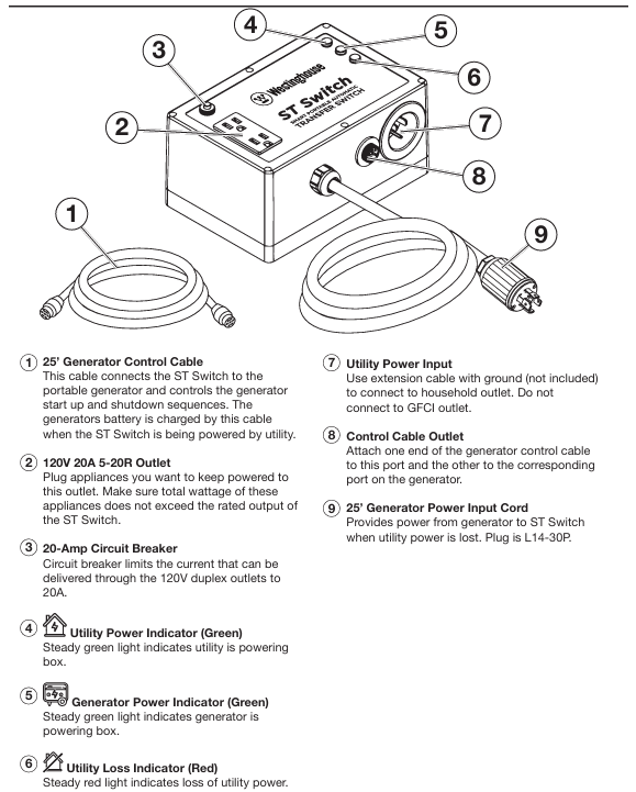
Interface configuration: 120V 20A 5-20R dual socket, grid power input port, generator control cable interface, 25 foot generator power cord.
Protection configuration: 20A circuit breaker to prevent overload damage to equipment.
Westinghouse ST Switch Intelligent Automatic Portable Transfer Switch
Core parameters and compatibility
1. Key specifications
Output parameters: 120V, 20A, 60Hz, maximum output power matching generator operating power of 2400W.
Input parameters: Grid input 120V 20A 60Hz, generator input 120V 20A 60Hz (equipped with L14-30P plug).
Interface configuration: 120V 20A 5-20R dual socket, grid power input port, generator control cable interface, 25 foot generator power cord.
Protection configuration: 20A circuit breaker to prevent overload damage to equipment.
2. Compatibility requirements
Only compatible with Westinghouse generators with "Smart Switch Ready" interface, not compatible with other brands or generators without this interface.
Do not use in series with other conversion switches, do not connect GFCI sockets or use socket adapters.
Core functions and working principles
1. Full process working mechanism
(1) When the power grid is normal (standby mode)
Power supply path: grid power supply → transfer switch → connected electrical appliances. At this time, the green "grid power indicator light" is constantly on.
Additional function: The generator battery is continuously charged by the power grid through the generator control cable, ensuring that the generator battery is fully charged and can be started at any time.
Key state: The generator is in the "RUN" position but not starting, only the battery charging circuit is working.
(2) When the power grid is cut off (emergency power supply state)
Trigger mechanism: When the conversion switch detects a power outage in the power grid, the red "power grid interruption indicator light" immediately lights up.
Start up process: After a delay of 5-10 seconds (to avoid accidental triggering due to instantaneous fluctuations in the power grid), send a start signal to the generator through the control cable, and the generator will automatically start and enter a stable operating state.
Switching power supply: After the generator output stabilizes (within about 30 seconds), the transfer switch automatically cuts off the power grid circuit and connects the generator power supply circuit. The green "generator power indicator light" lights up, and the electrical appliances are powered by the generator.
(3) When the power grid is restored (switching and cooling state)
Detection process: After the power grid is restored, the transfer switch first undergoes a 5-10 second stability test (to prevent frequent switching caused by voltage fluctuations in the power grid), and at this time, the red and green indicator lights are constantly on.
Switching power supply: After confirming the stability of the power grid, cut off the generator power supply circuit, connect the power grid circuit, the red "power grid interruption indicator light" will turn off, and the electrical appliances will resume power supply to the grid.
Cooling shutdown: The switch keeps the generator running for 45-50 seconds during the cooling period to avoid damage to the engine caused by high-temperature shutdown. After the cooling is complete, the generator will automatically shut down and the green "generator power indicator light" will turn off.
2. Full analysis of indicator lights (including abnormal states)
Description of indicator light combination status and operation suggestions
Only the green grid light stays on and is in normal standby mode. The power is supplied by the grid, and there is no need to operate the generator battery during charging. Regularly check the cable connections
Only the red power grid interruption light remains on. The power grid has been cut off, and we are waiting to start the generator to confirm that the fuel and oil are sufficient and there are no fault alarms
Only the green generator light is constantly on, and the power grid has not been restored to monitor the operation status of the generator to ensure sufficient fuel supply
The traffic lights are constantly on at the same time, and the power grid has been restored. Stability testing will be conducted and wait for 5-10 seconds without manual intervention
The green light stays on and the red light flashes. The power grid is restored but the voltage is unstable. Keep observing. If it does not return to normal within 1 minute, check the power grid line
The generator light is constantly on+the grid light is flashing. The generator power supply is normal, and the grid is in a fluctuating state without operation. The transfer switch will continue to monitor the grid
No indicator light is on, the conversion switch is not connected to the power grid, or there is an internal fault. Check if the power grid connection line is tightly plugged in. If the connection is normal, it needs to be reported for repair
Safety operation standards (including risk avoidance)
1. Installation and placement safety
Generator placement requirements:
It must be placed in an outdoor ventilated area, at least 15 feet (about 4.6 meters) away from the doors, windows, and ventilation openings of the house, to prevent carbon monoxide exhaust from entering the room.
Place on a hard, level surface to avoid tilting and causing fuel leakage; Keep a safe distance of at least 3 feet (approximately 0.9 meters) away from flammable materials such as hay, wood, and paint.
It is prohibited to place the generator on rainy, snowy, or damp ground. A temporary rain shelter (not enclosed) must be built to prevent rainwater from entering the generator and causing a short circuit.
Requirements for placement of transfer switch:
Only suitable for indoor use, placed in a dry, ventilated, away from water sources (such as kitchens, bathrooms) and flammable materials.
Do not place it in areas prone to water accumulation such as basements and low-lying areas to avoid equipment short circuits caused by floods or water leaks.
The placement height should be at least 1 foot (about 0.3 meters) above the ground to prevent moisture erosion on the ground.
2. Cable connection safety
Connection sequence: The power grid must be connected first, then the generator control cable, and finally the generator power line. It is forbidden to reverse the sequence.
Cable requirements:
Grid input extension cable: A grounded three core cable with no damage or aging is required, with a length not exceeding 30 feet (approximately 9.1 meters) and a core cross-sectional area of ≥ 1.5mm ².
Generator control/power cord: The total length should not exceed 50 feet (approximately 15.2 meters). If extension is required, Westinghouse original extension cords (model 3021225C is the power cord extension cord, STCORD25 is the control cable extension cord) must be used. Non original cables are prohibited.
Connection operation:
All connections must be made after the generator is turned off and cooled down, and the plug must be fully inserted into the interface and locked to avoid loosening and overheating.
After connection, check that the cables are not twisted or compressed, and keep them away from high-temperature components such as the generator exhaust pipe to prevent cable aging.
3. Safety of electrical loads
Load accounting rules:
Pure resistance load (light bulb, heater, rice cooker): total operating power ≤ 20A × 120V=2400W.
Inductive loads (motors: refrigerators, water pumps, air conditioners): starting power=operating power multiplied by multiple (small handheld devices multiplied by 1.2, large fixed devices multiplied by 3.5), total starting power ≤ 2400W.
Example: 1500W space heater (pure resistor)+700W refrigerator (starting power 700 × 3.5=2450W), total starting power 2450W>2400W, cannot be connected simultaneously; 1500W heater+500W furnace (starting power 500 × 1.2=600W), total starting power 2100W ≤ 2400W, can be connected simultaneously.
Taboo for load connection:
Prohibit the connection of electrical appliances with unknown power to avoid overload triggering circuit breaker tripping.
It is prohibited to simultaneously connect multiple large inductive loads (such as two air conditioners, one water pump+one air conditioner) to prevent excessive starting power.
When connecting electrical appliances, it is necessary to first turn off the electrical switch and then turn it on again to avoid arcing caused by load insertion and removal.
4. Emergency safety handling
Generator malfunction unable to start: Immediately disconnect the transfer switch from the generator, manually start the generator to troubleshoot (such as low fuel, low oil, spark plug malfunction), and reconnect after troubleshooting.
The transfer switch does not switch the power supply: check the status of the indicator light. If the red light is on after the power grid is cut off but the generator does not start, check the connection of the control cable; If the green light does not turn on after the generator is started, check the power cord connection and restart the transfer switch if necessary (unplug the power grid for 30 seconds and then reinsert it).
Fire/Leakage Emergency: Immediately shut down the generator, unplug all connecting wires of the transfer switch, and use ABE or BE class fire extinguishers to extinguish the fire (water is prohibited from extinguishing electrical fires); If electric shock occurs, immediately cut off the power and seek medical attention.
Operation process (setup+testing+daily use)
1. Initial process setup (required steps)
Generator preparation:
Place the generator in a safe outdoor location, check that the fuel (unleaded gasoline) and engine oil (four stroke engine oil that meets the requirements of the generator) levels are normal, and that the battery connection is secure.
Start the generator and test it to run normally independently. After confirming that there are no fault alarms, turn it off and cool it down to room temperature.
Switch connection:
Place the transfer switch in a dry indoor location, connect the grid power supply to the "grid power input port" of the transfer switch with a grounding extension wire, and the green grid indicator light will light up at this time.
Connect the generator control cable: Insert one end into the "Smart Switch Ready" interface of the generator and the other end into the "Control Cable Interface" of the conversion switch. You can hear the locking sound of the buckle.
Connect the generator power cord: Insert the 25 foot power cord L14-30P plug that comes with the conversion switch into the generator L14-30R socket, and tighten the fixing nut.
Electrical connections and generator settings:
Connect the electrical appliances that require emergency power supply (such as refrigerators and heaters) to the 120V dual socket of the conversion switch to ensure that the total power does not exceed the standard.
Turn on the "RUN" switch of the generator, confirm that the generator battery indicator light is on (indicating that the charging circuit is normal), and complete the first setting.
2. Functional testing process (must be done before first use)
Test purpose: To verify that the automatic switching function of the transfer switch is normal and to avoid failure in emergency situations.
Test preparation: Ensure all connections are complete, connect a small appliance (such as a desk lamp, phone charger), and confirm that the appliance is powered by the power grid normally.
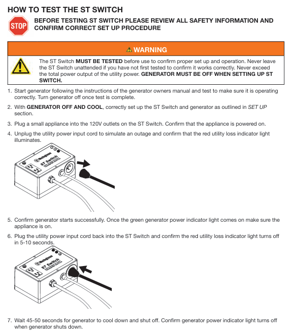
Simulated power-off test:
Unplug the power grid input extension line of the conversion switch and simulate a power outage in the power grid.
Observe the indicator light: The red power grid interruption light will immediately turn on, and the generator will automatically start after 5-10 seconds.
Confirm switch: About 30 seconds after the generator starts, the green generator light will turn on, and the electrical appliances will be powered by the generator normally.
Simulated recovery test:
Re insert the power grid input extension line to simulate power grid recovery.
Observe the indicator lights: both traffic and green lights remain on (5-10 second detection period), then the red light goes out and the electrical appliances resume power supply to the grid.
Confirm shutdown: Wait for 45-50 seconds, the generator will automatically shut down, the green generator light will turn off, and the test is complete.
Exception handling: If a step in the test is not executed as expected, check if the cable connection is secure and if the generator is in the "RUN" position. After troubleshooting, retest.
3. Daily use and emergency activation process
(1) Daily maintenance (non emergency state)
Every month: Check if all cable connections are secure, without damage or aging; Start the generator and run it for 10 minutes to ensure that there are no faults in the generator.
Every 6 months: Conduct a complete test of the transfer switch according to the "functional testing process" to ensure that the automatic switching function is normal; Check the battery level of the generator and recharge it if necessary.
Long term use (exceeding 3 months): Disconnect the transfer switch from the power grid and generator, store the transfer switch in a dry environment, and maintain the generator according to long-term storage requirements.
(2) Emergency use (sudden power outage in the power grid)
No manual operation required: The switch automatically completes the entire process of "detecting power failure → starting the generator → switching power supply".
Key monitoring: Observe the status of the conversion switch indicator light and confirm that it switches as expected; Monitor the fuel level of the generator and replenish fuel if necessary under safe conditions (operate after shutting down the generator and cooling it down).
After the power grid is restored: without intervention, the transfer switch automatically switches back to the grid and shuts down the generator. After the generator cools down, its "RUN" switch can be turned off (or kept on for the next emergency start).
Maintenance and Warranty
1. Key points of maintenance and upkeep
Switch maintenance:
Cleaning: Use a dry cloth to wipe away surface dust. Do not use water or solvents for cleaning to prevent liquids from entering the interface.
Storage: When not in use for a long time, disconnect all connections and place in a dry, ventilated storage box, avoiding direct sunlight and high temperature and humidity environments.
Testing: Conduct a functional test every 6 months to ensure that there are no faults in the internal circuit.
Cable maintenance:
Regularly inspect the cable sheath for any damage or cracking, and ensure that the plug has no signs of oxidation or erosion.
Avoid excessive bending and squeezing during storage to prevent internal core breakage; The generator end cable should be kept away from high-temperature components such as exhaust pipes.
2. Detailed explanation of warranty policy
Warranty period: 1 year from the date of purchase, covering faults caused by material and process defects.
Warranty scope: For quality issues with the main body of the conversion switch and original cables (control cables, power cords), free repair or replacement of faulty components is provided.
Not covered by warranty:
Human damage (such as falling, collision, liquid immersion, overload use).
Unauthorized maintenance and modification (such as splicing cables, replacing non original components).
Normal wear and tear (such as plug contact wear), damage caused by natural disasters or accidents.
Malfunctions caused by failure to follow the manual, such as connecting incompatible generators or illegally extending cables.
Common troubleshooting
Possible causes and solutions for fault phenomena
The generator does not start after the power grid is cut off. 1. The control cable is not properly connected; 2. Insufficient battery power in the generator; 3. The generator is in the "OFF" position; 4. Generator malfunction (insufficient fuel/oil, alarm lock) 1. Check if the control cable plug is securely plugged in; 2. Manually start the generator to charge the battery or replace the battery; 3. Confirm that the generator is in the "RUN" position; 4. Check for generator faults and solve them according to the generator manual
The power supply is not switched after the generator is started. 1. The power cord is not properly connected; 2. Generator output fault; 3. Overload protection trip of transfer switch 1. Check if the power cord plug is tightened; 2. Disconnect the conversion switch and directly use the generator to supply power to the electrical appliance, verifying the output of the generator; 3. Disconnect part of the load and press the reset button of the circuit breaker on the transfer switch
After the power grid is restored, it will not switch back to the grid. 1. The voltage of the power grid is unstable; 2. Switch detection circuit fault 1. Use a multimeter to measure the grid voltage (normal 110-130V) and eliminate the grid problem; 2. Restart the conversion switch (unplug for 30 seconds and then reinsert), if it still does not work, report for repair
Abnormal flashing of indicator light: 1. Grid voltage fluctuation; 2. Internal circuit failure of the transfer switch. 1. Observe the restoration of the power grid and contact the power company if there is continuous fluctuation; 2. If the issue persists after disconnecting all connections and restarting, report for repair
Frequent tripping of circuit breakers: 1. The total power of the connected electrical appliances exceeds the standard; 2. Electrical short circuit; 3. Cable damage and short circuit: 1. Reduce the number of connected electrical appliances and calculate the total power; 2. Disconnect all electrical appliances and connect them one by one to check for short-circuit devices; 3. Check if the cable is damaged and replace the faulty cable
- YOKOGAWA
- Reliance
- ADVANCED
- SEW
- ProSoft
- WATLOW
- Kongsberg
- FANUC
- VSD
- DCS
- PLC
- man-machine
- Covid-19
- Energy and Gender
- Energy Access
- Renewable Integration
- Energy Subsidies
- Energy and Water
- Net zero emission
- Energy Security
- Critical Minerals
- A-B
- petroleum
- Mine scale
- Sewage treatment
- cement
- architecture
- Industrial information
- New energy
- Automobile market
- electricity
- Construction site
- HIMA
- ABB
- Rockwell
- Schneider Modicon
- Siemens
- xYCOM
- Yaskawa
- Woodward
- BOSCH Rexroth
- MOOG
- General Electric
- American NI
- Rolls-Royce
- CTI
- Honeywell
- EMERSON
- MAN
- GE
- TRICONEX
- Control Wave
- ALSTOM
- AMAT
- STUDER
- KONGSBERG
- MOTOROLA
- DANAHER MOTION
- Bentley
- Galil
- EATON
- MOLEX
- Triconex
- DEIF
- B&W
- ZYGO
- Aerotech
- DANFOSS
- KOLLMORGEN
- Beijer
- Endress+Hauser
- schneider
- Foxboro
- KB
- REXROTH
- YAMAHA
- Johnson
- Westinghouse
- WAGO
- TOSHIBA
- TEKTRONIX
- BENDER
- BMCM
- SMC
- HITACHI
- HIRSCHMANN
- XP POWER
- Baldor
- Meggitt
- SHINKAWA
- Other Brands
- UniOP
- KUKA
- IBA
-
Woodward 9905-373 - Digital Synchronizer And Load Controller
-
WOODWARD MAGNETIC PICKUPS - Sensor
-
WOODWARD GCP-30 - Steuertafel for Industrial Regulator Genset Control Package
-
WOODWARD GOVERNOR 9907-1183 REV A - 505 ENHANCED TURBINE CONTROL
-
WOODWARD 9907-173 REV B - Module Load Sharing 120 Volt
-
WOODWARD 9907-014 - 2301A controller
-
Woodward 9905-029 - SPM-A Synchronizer Module Rev C
-
WOODWARD 8440-1799 EASYGEN-350 REV B - Genset Controller
-
WOODWARD 5466-258 REV M - SIMPLEX DISCRETE I/O MODULE
-
Woodward 8440-1884 C - Controller Easygen 2500-5
-
Woodward 8441-1153 - Monitoring Unit 250VAC
-
WOODWARD 8406-120 REV G - EGCP-2 DIGITAL CONTROL
-
Woodward 8273-584 - Atlas-ii Digital Control
-
Woodward 8272-582 - APM Motor Control 8272582
-
Woodward 9905-377 Rev. A - 2301A Load Sharing and Speed Control
-
WOODWARD 8272-517 - Pm Motor Control
-
WOODWARD 9905-797 REV.B - DIGITAL SYNCHRONIZER AND LOAD CONTROL DSLC-D
-
WOODWARD 8272-582 - APM MOTOR CONTROL
-
Woodward Seg FP2-8-24 - Emergency Power Telecommunications Module NP2
-
WOODWARD 2001-12E2U1B1S1A - Fuel Shut Off Valve Stop Solenoid Valve 2000-4505
-
Woodward 8440-1884 K - Genset Controller Easygen-2500-5
-
Woodward 9905-760 - Linknet Termination Module
-
Woodward 8404-009 - Proact Digital Plus Front Panel Rev. H
-
Woodward 8271-651 - Digital Speed Reference
-
Woodward 3077-474C - 8605895 5501-031 D Circuit Module
-
WOODWARD 5466-257 REV.-C - NETCON 5000 MODEL REMOTE TRANSCEIVER I/O MODULE
-
Woodward 8273-101 Rev: A - 2301D Digital Load Sharing and Speed Control
-
WOODWARD 8272-799 - 2301A SPEED CONTROL WITH REMOTE REFERENCE REV:C
-
Woodward 8272-517 - PM Motor Control
-
Woodward 8290-048 8290048 Rev. F - Generator Load Sensor
-
woodward 8273-1012 rev c - 2301e Load Sharing and Speed Control
-
WOODWARD 9905-797 - DIGITAL SYNCHRONIZER AND LOAD CONTROL FOR 3 PHASE GENERATORS
-
WOODWARD 8280-3014 - 723 PLUS DIGITAL CONTROL REV NEW
-
WOODWARD 8440-1884 REV G - GENSET CONTROLLER EASYGEN-2500-5/P1
-
Woodward 8272-683 K - Digital Reference
-
WOODWARD 9907-014 - SPEED CONTROL 2301A REV H
-
Woodward Type UG-8 P/N 037260 - Governor R.P.M 1075-1650 Motor KM58-20
-
WOODWARD 9905-970 - LINKNET 6 CHANNEL 100 OHM RTD Rev:J
-
Woodward 9907-1183 Rev C - Steam Turbine Digital SCREEN 505E Turbine Control
-
Woodward 8440-1614 - GCP-30 Genset Control Package, Rev: F, Type 1, E231544
-
Woodward DC11006-304-024 - ACTUOTOR DYNA ACTUATOR - BARBER-COLMAN
-
Woodward 9905-971 - LINKNET 6 CHANNEL 100 OHM RTD Rev:K
-
Woodward DYNK-10249 - Actuator Controller Kit - DYNA 2000
-
Woodward LR21035 - MFR1 MULTI FUNCTION RELAY REV F
-
Woodward 8440-1831 - EASYGEN 3200-5 P/N: REV. G Gererator Controller
-
Woodward 8272-516 - PM MOTOR CONTROL REV J
-
Woodward 8440-2080 - EASYGEN 2000 genset controller EASYGEN-2300-5/P1
-
Woodward 505DE - Digital Control System
-
Woodward 701 - Digital Speed Control 18-40 VDC 4-20 MA
-
Woodward 8440-1799 - EASYGEN-350 REV B
-
Woodward 8272-582 - Apm Motor Control 100-220v AC/DC
-
Woodward 5501-031 D - 3077-474C 8605895 Circuit Module
-
Woodward XD1-T - XD1T55SAT TRANSFORMER DIFFERENTIAL PROTECTION RELAY
-
Woodward 8272-517 - PM Motor Control 220vac
-
Woodward 8934-658 - Repair Kit UG8D Governor
-
Woodward 5437 18 - module netcon derivative analog rev.A
-
Woodward 8272-171 A - Pm Motor Control
-
Woodward MRN3-1/2 - SEG mains uncoupling relay MRN314D mains decoupling relay
-
Woodward 9905-373 - Digital Synchronizer and Load Control 18-40 VDC Rev P
-
Woodward 5431-640 C - Dual Dynamics 1000 Series Speed Control Module
-
Woodward 5501-031 D - 3077-474C 8605895 Circuit Module
-
Woodward 9907-247 - 828 DIGITAL CONTROL
-
Woodward 8440-1855-G - EASYGEN-2200-5 /P1 12/24VDC GENSET CONTROLLER
-
Woodward NC3-2-8 (NO) - GENERATOR CONTROLLER
-
Woodward 8271-467 K - 2301 LOAD SHARING AND SPEED CONTROL PART NO:
-
Woodward 8440-2177 A - SPM-D2-10 Digital Synchronising Controller
-
Woodward LXMG1614E-14-11 - CCFL and UV Lamps Inverter Module
-
Woodward 8270-990 - signal converter
-
Woodward 9905-068 - LOW VOLTAGE 2301A LOAD SHARING & SPEED CONTOL P/N:
-
Woodward 8901-051 - BOOSTER SERVOMOTOR, SINGLE CYLINDER, 2:1
-
Woodward 8444-1024 D - MWS4-55M CONTROL MODULE UNIT
-
Woodward 5448-914 - GCP-20 Genset Control GCP-20 REV D P/n:
-
Danfoss BHA-1 018-1942 - Hydraulic Actuator
-
Woodward 9905-001 L - SPM-A SYNCHRONIZER
-
Woodward 5464-850 - Module
-
Woodward 5501-371 - Micronet Simplex Mpu Aio Rev C
-
Woodward 8272-132 B - POWER SENSOR
-
Woodward 9907-028 - SPM-A Synchronizer
-
Woodward SA-3678-AM-2 - Overspeed Electric Governor, Model ESSE2-AM
-
Woodward E8250-502 - GOVERNOR ACTUATOR
-
Woodward 8440-1884 J - Controller EASYGEN-2500-5
-
Woodward 5441-693 - DIGITAL I/O MODULE -MISSING PART
-
Woodward SA-4450 - Speed Controller APECS 3100 For Magnetic Pickup
-
Woodward 9903-466 - 701 DIGITAL SPEED CONTROL REV G
-
Woodward 1765-843 - Governor Speed Adjusting Motor P/N Type: SMM40 220V AC 50/60Hz
-
Woodward 9905-760 - Linknet Termination Module
-
Woodward 9907-247 - 828 DIGITAL CONTROL UNIT REV K
-
Woodward 5484-721 - motor
-
Woodward 8440-1734 - MFR-2 Rev.A Multi Function Relay MFR-2
-
Woodward CSC3SUWA - Controller
-
Woodward 8440-1667 - REV B SPM-D1010B/XN
-
Woodward 8406-120 - egcp-2 digital control
-
Woodward DPG-2201-002 - DIGITAL CONTROLLER REV D
-
Woodward 8272-516 - Pm Engine Control Rev J
-
Woodward 8440-1831 - EASYGEN 3200-5 P/N: REV. K - WITHOUT ACCESSORIES
-
Woodward 8273-101 - LOAD SHARING & SPEED CONTROL
-
Woodward 8440-1855-G - EASYGEN-2200-5 /P1 12/24VDC GENSET CONTROLLER
-
Woodward 9907-247 - 828 DIGITAL CONTROL UNIT REV K
-
Woodward LR21035 - MFR1 MULTI FUNCTION RELAY REV J
-
Woodward 8404-009 - PROACT DIGITAL PLUS FRONT PANEL REV J
-
Woodward 9905-204 - Rev N SPM-A synchronizer
-
Woodward 8521-367 - UG-8 P/N r R.P.M 750-1280 Governor / UG8
-
Woodward 9907-175 - Load Sharing Module Rev. B
-
Woodward 5464-645 - DRIVER MODULE REV A 2C ACT DRIVE
-
Woodward 8404-009 - PROACT DIGITAL PLUS FRONT PANEL REV J
-
Woodward 9907-175 - Load Sharing Module Rev. B
-
Woodward 8406-102 - Rev A EGCP-2 Digital Control Engine Generator 8406102
-
Woodward EASYGEN-2500-5 - Controller Genset
-
Woodward 8440-2082 - Controller
-
Woodward 8272-516 - PM MOTOR CONTROL REV J
-
Woodward 9905-373 - Digital Synchronizer and Load Control 18-40 VDC Rev P
-
Woodward 5501-429 - Actuator Controller 25mA 2 Channel , (UPP)
-
Woodward 8440-1869 - SPM-D10 Synchronizing System Control-SPM-D10B/PSY4-F-D
-
Woodward 9907-175 - Load Sharing Module Rev. A
-
Woodward 8200-224 - Servo Position Controller
-
Woodward 9906-619 - 723 PLUS DIGITAL CONTROL ( 8280-604 )
-
Woodward 8440-1519 - EASYGEN PART NO: REV: 4
-
Woodward 5501-371 - REV C MODULE- MICRONET SIMPLEX MPU & AIO FTM
-
Woodward EASYGEN-3200-5/P1 - Generator Controller Module Rev F
-
Woodward 8440-1884K - GENERATOR CONTROLLER EASYGEN-2500-5 REV,K
-
Woodward 5466-353 - REV C NETCON MAIN CHASSIS TRANSCEIVER
-
Woodward 9905-001 - SPM-A SYNCHRONIZER REV.L
-
Woodward 9907-838 - Speed control panel 9907-838 9907838
-
Woodward 9907-164 - 505 Digital Governor Turbine Control
-
Woodward 8273-465 - ATLAS W/O PC104 MODULE
-
Woodward 8200-1504 - Peak200 Steam Turbine Control Front Panel Mount HVAC Rev:E
-
Woodward 8272-582 - Apm Motor Control 100-220v AC/DC
-
Woodward 8440-1884 C - Controller Easygen 2500-5

K-JIANG

Add: Jimei North Road, Jimei District, Xiamen, Fujian, China
Tell:+86-15305925923