
K-WANG
+086-15305925923
Service expert in industrial control field!


Product
Article
NameDescriptionContent
Adequate Inventory, Timely Service
pursuit of excellence


Ship control system
Equipment control system
Power monitoring system
Current position:
新闻动态
newS
Brand
ABB Switches Automatic Transfer Switches
ABB Switches Automatic Transfer Switches
ABB Switches Automatic Transfer Switches
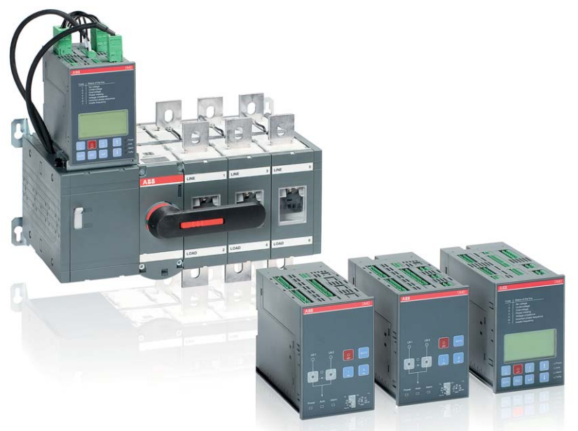
ABB’s range of automatic transfer switches goes from
160 to 1600 Amperes. There are three types of ATSs with
three different OMD control units: OMD200, OMD300 and
OM800. ABB’s ATSs have the features and functionality
that makes them suitable for diverse applications:
industrial plants, docks, airports and data centers.
Safe and reliable operation
The change-over mechanism has three stable positions,
which ensure isolation of the two asynchronous power
supplies.
No risk of short circuit between the sources, even in the
presence of transient voltages
The switch has a selector to choose between manual and
automatic operation. Automatic operation is disabled by
padlocking the latch or by fitting the handle. Both manual
and automatic operation can be prevented by padlocking the
handle in O position.
Unwanted operation prevented
Manual operation is always possible in emergency situations,
even without electricity.
All-time safe and reliable operation
Easy installation
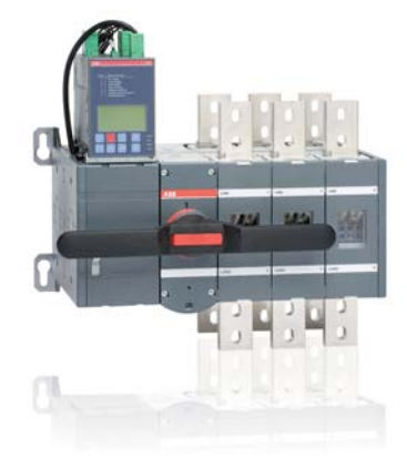
The design of ABB automatic transfer switch is advanced and
compact. The OMD control unit can be adjusted according to
the depth of the panel and the voltage sensing kit is installed
at the factory.
Reduce installation cost and time
The motor operator of the ATS is protected by a fuse. If the
operation frequency is exceeded, the fuse protects the motor.
No more expensive repair work
It is also possible to purchase the control units and motorized
change-over switches as separate components, so the users
can build the automatic transfer switch by themselves if desired.
User friendly interface
The panels of the OMD control units show the status of
the system clearly: line status, switch position, alarms and
operation mode (manual or automatic). The OMD can be
configured in an easy way.
OMD800 shows the information on a LCD display, with menus
available in eight languages.
Simplicity of usage
Fully automatic solution. Our ATS range
includes sophisticated features in
extremely compact footprint area without
neglecting features that makes assembly
easy and safe, every time.
Data according to IEC 60947-3 Switch size OTM160_
Rated insulation voltage and rated Pollution
operational voltage AC20 degree 2 V 415
Dielectric strength 50 Hz 1min. kV 10
Rated impulse withstand voltage kV 6
Rated thermal current and rated operational / ambient 40°C In open air A 160
current AC20 / ambient 40°C In enclosure A 160
..with minimum conductor cross section Cu mm2 70
Rated operational current, AC-21A up to 415 V A 160
Rated operational current, AC-22A up to 415 V A 160
Rated operational current, AC-23A up to 415 V A 160
Rated operational power, AC-23A1) 230 V kW 45
The kW-ratings are accurate for 3-phase 1500 400 V kW 90
R.P.M. standard asychronous motors 415 V kW 90
Rated breaking capacity in category AC-23 up to 415 V A 1 280
Rated conditional short-circuit current Ip (r.m.s.) and Ip (r.m.s.) 80 kA, 415 V îc
(peak) kA 40.5
cut-off current îc
(peak) value. The cut-off current îc Max. OFA_ fuse size gG/aM A/A 355/315
refers to values listed by fuse manufacturers
(single phase test acc. to IEC60269).
Rated short-time withstand current Icw (r.m.s.) 415 V 0.15s kA 15
415 V 0.25s kA 15
415 V 1s kA 8
Rated short-time making capacity2) I
cm (peak)3) 415 V kA 30
Power loss / pole With rated current W 2.4
Mechanical endurance Number of oper. cycles4) Cycles 8 000
Mechanical endurance / switch Number of operations Oper. 16 000
Terminal bolt size Metric thread diameter x length mm M8x25
Terminal tightening torque Counter torque required Nm 15-22
Operating torque Typical for 3-pole switches Nm 7
Weight without accessories 3-pole switch kg 5.7
4-pole switch kg 6.4
Data according to IEC 60947-6-1
Class of equipment PC
Rated short-time withstand current Icw (r.m.s.) 415 V 0.1s kA 15
Rated operational current, AC-31B up to 415 V A 160
Rated operational current, AC-33B up to 415 V A 160
1) These values are given for guidance and may vary acc. to the motor manufacturer
2) Short circuit duration > 50 ms, without fuse protection
3) Max. distance from switch frame to nearest busbar / cable support 150 mm
4) Operating cycle: O - I - O - II - O
OTM200_ OTM250_ OTM315_ OTM400_ OTM630_ OTM800_ OTM1000_ OTM1250_ OTM1600_
415 415 415 415 415 415 415 415 415
10 10 10 10 10 10 10 10 10
666666666
200 250 315 400 630 800 1 000 1 250 1 600
200 250 315 400 630 800
95 120 185 240 2x185 2x240 2x300 2x400 2x500
200 250 315 400 630 800 1 000 1 250 1 600
200 250 315 400 630 800 1 000 1 250 1 600
200 250 315 400 630 800 1 000 1 250 1 250
60 75 100 132 200 250 315 400 400
110 140 160 220 355 450 560 710 710
110 145 180 230 355 450 560 710 710
1 600 2 000 2 520 3 200 5 040 6 400 10 000 10 000 10 000
40.5 40.5 59 59 83.5 83.5 100 100 100
355/315 355/315 500/500 500/500 800/1 000 800/1 000 1 250/1 250 1 250/1 250 1 250/1 250
15 15 31 31 38 38 50 50 50
15 15 24 24 36 36 50 50 50
8 8 15 15 20 20 50 50 50
30 30 65 65 80 80 92 92 92
4 6.5 6.5 10 25 40 19 29 48
8 000 8 000 8 000 8 000 5 000 5 000 3 000 3 000 3 000
16 000 16 000 16 000 16 000 10 000 10 000 6 000 6 000 6 000
M8x25 M8x25 M10x30 M10x30 M12x40 M12x40 M12x60 M12x60 M12x60
15-22 15-22 30-44 30-44 50-75 50-75 50-75 50-75 50-75
7 7 16 16 27 27 78 78 78
5.7 5.7 10.2 10.2 17.5 17.5 42 42 44
6.4 6.4 11.4 11.4 20.4 20.4 50 50 52
PC PC PC PC PC PC PC PC PC
15 15 25 25 38 38 50 50 50
200 250 315 400 650 720 1 000 1 250 1 600
200 250 315 400 650 650 1 000 1 000 1 000

Technical data
Automatic transfer switches/power circuit
and dual power source
Technical data for automatic transfer switches, power circuit
OTM_C2D_ (OMD200)
Rated operational voltage Ue 208 - 415 V AC +/- 20 % + N
Phase - Neutral 120 - 240 V AC +/- 20 %
Rated frequency 50 / 60 Hz +/- 10 %
Rated impulse withstand voltage Uimp 6 kV
OTM_C3D_ (OMD300)
Rated operational voltage Ue 208 - 415 V AC +/- 20 % + N
Phase - Neutral 120 - 240 V AC +/- 20 %
Rated frequency 50 / 60 Hz +/- 10 %
Rated impulse withstand voltage Uimp 6 kV
OTM_C8D_ (OMD800)
Rated operational voltage Ue
on 3 phase system 100 - 415 V AC +/- 20 %
Phase - Neutral 57,7 - 240 V AC +/- 20 %
Rated operational voltage Ue
on 1 phase system1) 57,7 - 240 V AC +/- 20 %
Rated frequency 50 / 60 Hz +/- 10 %
Rated impulse withstand voltage Uimp 6 kV
AUX voltage1) 24 V DC - 110 V DC (-10 to 15 %)
Operating temperature - 5…+40°C
Transportation and storage temperature - 25…+70°C
Altitude Max.2000m
1) If on 1 phase system the voltage level is between 57,7 – 109 V AC, AUX voltage supply must be used
Technical data for dual power source ODPSE230C
Dual power source ODPSE230C
Rated operational voltage U [V] 220…240 V AC +/- 20%
Rated frequency 50 / 60 Hz +/- 10%
Short-circuit protection device Max. MCB 4 A
Nominal output current In
[A] 4 A
Startup time Max. 1.0 s (with 230 V AC)
Operating transfer time LN1 - LN2 or LN2 - LN1 Max. 0.5 s (with 230 V AC)
Cable size 0,2…2,5 mm2
Rated impulse withstand voltage, Uimp 4 kV
Overvoltage category III
Pollution degree 3
Protection rating for the front panel IP20
Operating temperature – 25...+ 60 °C
Transportation and storage temperature – 40...+ 70 °C
Altitude Max. 2000m
Technical data, motor operator
Automatic transfer switches
Technical data for motor operator, control circuit
Motor operator, control circuit OTM160…250 OTM315…400 OTM630…800 OTM1000…1600
Rated operational voltage U [V] Pollution degree 3 50/60 Hz 220 - 240 V AC
Operating voltage range 0,8…1,2 x Ue
Operating times See the table below
Nominal current In
a) A 0.2 0.5 0.7 1.8
Current Inrusha) A 1.3 2.1 2.8 7.7
Overload fuse Type / In / Capacity mA T/315/H T/500/H T/1000/H T/2000/H
Size mm 5x20 5x20 5x20 5x20
Operating rate Cycle 0 - I - 0 - II - 0
Max. continuous cycles / min 1 1 1 0.5
Max. short-time ≤ 10 cycles cycles / min 10 10 10 5
Overvoltage category III
Rated impulse withstand voltage Uimp kV 4
Dielectric strength 50 Hz 1 min. kV 1.5
Terminals
Voltage supply wiring for U PE - N - L
Cross section solid/stranded mm2 1.5 - 2.5
Short-circuit protection device max. MCB A C16
State information of locking (no SELV)
Cross section solid/stranded mm2 1.5 - 2.5
Locking motor operator 23-24 (NO) 5A/250V/cosϕ=1
Short-circuit protection device Max. MCB A C2
Protection degree IP20
Operating temperature °C -25…+55
Transportation and storage temperature °C -40…+70
Max. altitude m 2000
Operating times
Type
Operating transfer timea)
I - II, II - I [s]
OFF-time when operatinga)
I - II, II - I [s]
OTM160…250_C2D_ 2.0 - 4.0 0.4 - 1.0
OTM160…250_C3D_ 2.0 - 4.0 0.4 - 1.0
OTM160…250_C8D_ 1.5 - 3.0 0.4 - 1.0
OTM315…400_C2D_ 2.0 - 5.0 0.4 - 1.0
OTM315…400_C3D_ 2.0 - 5.0 0.4 - 1.0
OTM315…400_C8D_ 1.5 - 3.0 0.4 - 1.0
OTM630…800_C2D_ 2.0 - 5.0 0.4 - 1.0
OTM630…800_C3D_ 2.0 - 5.0 0.4 - 1.0
OTM630…800_C8D_ 1.5 - 3.0 0.4 - 1.0
OTM1000…1600_C2D_ 3.0 - 6.0 0.6 - 1.5
OTM1000…1600_C3D_ 3.0 - 6.0 0.6 - 1.5
OTM1000…1600_C8D_ 2.5 - 4.0 0.6 - 1.5
OTM_C_D products overview
Includes automatic control unit OMD200_ OMD300_ OMD800_
Manual operation with handle x x x
Local operation with front panel keypad x x x
Automatic transfer switching equipment (ATSE) x x x
Dual power source for the motor operator1) oxo
Measurements
Three phase voltage measurement on LINE 1 x x x
Single phase voltage measurement on LINE 1 x x x
Three phase voltage measurement on LINE 2 x x x
Single phase voltage measurement on LINE 2 x x x
Frequency on LINE 1 x x x
Frequency on LINE 2 x x x
Possibility to check the measurements via LCD x
Source failure detections
No voltage x x x
Undervoltage x x x
Overvoltage x x x
Phase missing x x x
Voltage unbalance x x x
Invalid frequency x x x
Incorrect phase sequence x
Configuration
By DIP switches x x
By rotary switches x x
By keypad and LCD x
Voltage threshold setting x x x
Voltage hysteresis setting x
Frequency threshold setting x
Frequency hysteresis setting x
Time delays
Switching delay x2) x2) x
Delay on transfer3) x
Dead band time I-II (stop switching to position O) x
Back-switching delay x4) x4) x
Dead band time II-I (stop switching to position O) x
Generator stop delay x5) x5) x
Status of time delays on the LCD x
1) Dual power source allows the motor operator to be supplied by two separate voltage supplies.
This way the motor operator is always energized from the available line.
2) Four options: 0, 5, 10 or 30 seconds
3) Delaying the switching sequence before transferring to generator,
guaranteeing that in cold locations the generator is properly warmed up
4) Two options: the duration of back-switching delay is the same as Switching delay,
i.e. the time delay is same for I - II and II - I, or the back-switching delay is fixed 5 min
5) Two options: the duration of generator stop delay is the same as Switching delay or fixed 5 min
- YOKOGAWA
- Reliance
- ADVANCED
- SEW
- ProSoft
- WATLOW
- Kongsberg
- FANUC
- VSD
- DCS
- PLC
- man-machine
- Covid-19
- Energy and Gender
- Energy Access
- Renewable Integration
- Energy Subsidies
- Energy and Water
- Net zero emission
- Energy Security
- Critical Minerals
- A-B
- petroleum
- Mine scale
- Sewage treatment
- cement
- architecture
- Industrial information
- New energy
- Automobile market
- electricity
- Construction site
- HIMA
- ABB
- Rockwell
- Schneider Modicon
- Siemens
- xYCOM
- Yaskawa
- Woodward
- BOSCH Rexroth
- MOOG
- General Electric
- American NI
- Rolls-Royce
- CTI
- Honeywell
- EMERSON
- MAN
- GE
- TRICONEX
- Control Wave
- ALSTOM
- AMAT
- STUDER
- KONGSBERG
- MOTOROLA
- DANAHER MOTION
- Bentley
- Galil
- EATON
- MOLEX
- Triconex
- DEIF
- B&W
- ZYGO
- Aerotech
- DANFOSS
- KOLLMORGEN
- Beijer
- Endress+Hauser
- schneider
- Foxboro
- KB
- REXROTH
- YAMAHA
- Johnson
- Westinghouse
- WAGO
- TOSHIBA
- TEKTRONIX
- BENDER
- BMCM
- SMC
- HITACHI
- HIRSCHMANN
- XP POWER
- Baldor
- Meggitt
- SHINKAWA
- Other Brands
- UniOP
- KUKA
- IBA
- Beckhoff
- ADLINK
51
-
ADLINK HPCI-14S12U - Industrial Control Backplane 12PCI Backplane PCI-14S Passive Backplane
-
ADLINK PCIe-GIE74C - image acquisition card 4-CH GigE Vision PoE+ Frame Grabber
-
ADLINK PCI-8164 - control card 4-Axis Advanced Motion Controller Board
-
ADLINK PCIe-U304 - 4 Port USB3 PCIe Frame Grabbers USB Screw Hole Card
-
ADLINK PCI-9112 - Multi-Function Data Acquisition Card DAQ Card
-
ADLINK PCI-7432 - 51-12013-0A50 4-CH Isolated Numérique I/O PCI Cartes Digital I/O Card
-
ADLINK PCA-6106P3-0C1 REV.C1 - backplane 6-Slot Passive Backplane Board
-
ADLINK PCI-7224 - 24-CH Opto-Isolated Digital I/O PCI Board
-
ADLINK CPCI-7433R(G) - Digital Input Board Rear I/O CompactPCI Card
-
ADLINK EBP-13E4 - 51-46703-0A30 Industrial PC Backplane Passive Backplane
-
ADLINK PCIE-HDV62 - Image acquisition card High Definition Video Frame Grabber
-
ADLINK EBP-13E4 - 51-46703-0A30 Industrial Backplane Board Passive Backplane
-
ADLINK 90111-B1 / CPCI-6770 - PCB CPU MODULE CompactPCI Single Board Computer
-
ADLINK PCI-7248 - DATA ACQUISITION PCI CARD 48-CH Parallel Digital I/O Board
-
ADLINK PCI-7230 - 51-12003-0a50 board PCI7230 32-CH Isolated Digital I/O Card
-
ADLINK PCI2A000CB - 51-20000-0B30 Multi-Function DAQ Card Baseboard
-
ADLINK PCI-8134-005 - 4-Axis Motion Controller Card
-
ADLINK PCI-7224 - 24-CH Opto-Isolated Digital I/O PCI Card
-
ADLINK PCI-7434 - 64-CH Isolated Digital Output Card
-
ADLINK PCI-8132 - motion control card 2-Axis Servo & Stepper Controller
-
ADLINK PCI-8134 - Motion Controller PCI Card 4-Axis Controller Board
-
ADLINK PCI-8164 - Motion Control Card 51-12406-0A40 4-Axis Controller
-
ADLINK 51-12001-0C20 - Circuit Board Data Acquisition Interface Module Hardware
-
ADLINK NuPR0-840 - industrial control motherboard Full-Size PICMG CPU Board
-
ADLINK PCI-7444 - 51-12023-0A10 card 128-CH Isolated Digital Output Board
-
ADLINK PCI-1612B - data acquisition card 4-Port RS-232/422/485 Serial Communication Card
-
ADLINK PCI-6208V 009 - 8/16-CH 16-Bit Analog Output Cards PCB-I-E-482=6BX3
-
ADLINK NUPRO-935A/LV - industrial control motherboard Full-Size PICMG SBC Board
-
ADLINK PCI-9114DG - Multi-Function DAQ Card Data Acquisition PCI Card
-
ADLINK ACL-7130 - Data acquisition card Isolated Digital I/O Board
-
ADLINK ABX-6300D-4E1-BP - board ABX6300D4E1BP Video Interface Expansion Card
-
ADLINK CPCI-6940 - CPCI-6940/D1539/M16-0(EA)-000E 6U CompactPCI Processor Board
-
ADLINK NuPRO-760 - industrial control motherboard Half-Size PICMG SBC CPU Board
-
ADLINK IMB-M42H (G)-0020 - industrial control motherboard LGA1155 Micro-ATX Mainboard
-
ADLINK RTV-24 / PCI-MP4S - 51-12519-1C30 4-Channel Real Time Video Capture Board
-
ADLINK PCI-8134 - 4-Axis Servo & Stepper Motion Controller Card
-
ADLINK MXC-6101D - V.PC000.002.ST.00 Box PC Configurable Embedded Computer
-
ADLINK PCI-8134A - 51-12421-0A10 Motion Control Card 4-Axis Controller Card
-
ADLINK DIN-100S / DIN-100SA1 - Technology SCSI-II TB 100-PIN Terminal Block Board
-
ADLINK DIN-812M001 / DIN812M001 - 51-14034-0A1 51140340A1 Terminal Module Breakout Interface
-
ADLINK PCI-8164 - Servo motion control 4-Axis Advanced Controller Card
-
ADLINK PCIe-GIE64 - Acquisition card GigE Vision PoE+ Frame Grabber
-
ADLINK M-302 - Industrial control motherboard ATX PC Board Mainboard
-
ADLINK PCI-8134 - Motion Controller PCI Card 4-Axis Controller Board
-
ADLINK PCI-RTV24 - Image capture card Analog Video Frame Grabber
-
ADLINK PCI-8102 - Motion control card 2-Axis Servo & Stepper Controller Board
-
ADLINK PCI-9112 REV.B1 - Card Multi-Function Data Acquisition Card
-
ADLINK HSI-DI32-M-N / HSL-TB32-M-DIN - Discrete I/O MODULE Distributed Automation Module System
-
ADLINK PCI-7296 - IO card REV.A3 96-CH Parallel Digital I/O Card
-
ADLINK DIN-814P-A4 / 814Y - terminal board Motion Control Interface Block
-
ADLINK DIN-814P-A4 - 51-14056-0A10 PCB-I-E-2736=ZA01 Screw Terminal Board Breakout
-
ADLINK M-322 - motherboard Industrial Control Computer Mainboard
-
ADLINK NUPRO-406 REV:B1 - industrial control motherboard Full-Size PICMG CPU Board
-
ADLINK AMP-204C - card DSP-Based 4-Axis Advanced Pulse-Train Controller
-
ADLINK HPCI14S REV.B1 - industrial computer baseboard 14-Slot Passive Backplane
-
ADLINK PCI-7250 - 8-CH Relay Output & 8-CH Isolated DI PCI Card
-
ADLINK EBP-13E2 - baseplate Passive Backplane Industrial Computer Chassis Board
-
ADLINK LPCI-3488A - PCI-GPIB card 51-12801-0A30 acquisition card IEEE-488 Interface Board
-
ADLINK PCI-6216V-GL - 51-12201-0C30 16-CH 16-Bit Voltage Analog Output Card
-
ADLINK ACL-8454 - 16-CH Isolated Digital I/O & 4-CH Counter Card
-
ADLINK HPCI-9S7U - backplane Passive Backplane Compatible with NuPRO-A301 852 841 842
-
ADLINK DAQ-2010-007 - Simultaneous-Sampling Multi-Function Data Acquisition Card
-
ADLINK MP-C154 - 51-64205-0A10 Motion Control Card 4-Axis Controller Board
-
ADLINK MXE-202/mSSD16B/WiFi-BT - Matrix Rugged I/O Platform Embedded Fanless Computer
-
ADLINK CM-920-R-17 - PC/104-Plus Single Board Computer Module Intel Celeron M
-
ADLINK PCI-7250 NSMP - 8-CH Relay Output & 8-CH Isolated DI Card
-
ADLINK PCI-8164 - 4-Axis Motion Controller PCI Card W/ Cable and Breakout Box
-
ADLINK EMX-100 - Ethernet-based 4-axis Motion Controllers Distributed Motion Module
-
ADLINK PCI-8134A - Press control card 4-Axis Motion Controller Board
-
ADLINK M-845EG REV:3.2 - industrial motherboard Pentium 4 Socket 478 Micro-ATX
-
ADLINK PCI-9114A Rev A2 DG - card High-Resolution Multi-Function Data Acquisition Board
-
ADLINK IEC-915GV - REV 1.1 Industrial motherboard Socket 478 CPU Board
-
ADLINK PCI-9111DG(G) - Data Acquisition Card Multi-Function DAQ Card
-
ADLINK HPCI-15S10 REV:B2 - Industrial computer base plate Passive Backplane Board
-
ADLINK NuPR0-840 / NuPR0-840DV - industrial control motherboard Full-size PICMG CPU Board
-
ADLINK RTV-24 / PCI-MP4S - 51-12519-1C30 4-Channel Real Time Video Capture Board
-
ADLINK NUPRO-780 - industrial control motherboard Pentium III Single Board Computer
-
ADLINK PCI-7296 - 0050 card 96-CH Opto-Isolated Parallel DIO Card Set
-
ADLINK NUPRO-780 - industrial control motherboard PICMG Full-Size SBC
-
ADLINK PCI-7248 - 51-12006-0A3 002 Pci 7248 48-CH Parallel Digital I/O Card
-
ADLINK PCI-7230 - 32-CH Isolated Digital I/O Card
-
ADLINK AMP-204C - motion control card 4-Axis Advanced Controller Board
-
ADLINK PCI-1714UL - Card Ultra High-Speed 4-CH Simultaneous Sampling DAQ
-
ADLINK NuPRO-E330 - industrial computer equipment motherboard PICMG 1.3 SHB SBC
-
ADLINK AMP-204C - DSP-Based 4-Axis Advanced Pulse-Train Motion Controller Module
-
ADLINK PCI-7256 - 001 51-12206-0A2 REV.A2 LPCI-7256 16-CH Latching Relay Output Card
-
ADLINK ND6050 - NUDAM DIGITAL I/0 MODULE Distributed I/O Unit
-
ASEM BM100 - Box PC Embedded Fanless Industrial Computer
-
ADLINK PCI-7250 - PCI Acquisition Card 8-CH Relay Output & Isolated DI Board
-
ADLINK PCI-8164 - Servo motion control 4-Axis Controller Card
-
ADLINK NuPRO-A40H - Industrial Motherboard 51-41807-1A30 OSP LGA1155 H61
-
ADLINK ADMAX X300 SERVER - 51066010-0A30 motherboard Multi-Processor Mainboard
-
ADLINK CMe-GIE62+ - 51-32903-0A30 control card PC/104-Plus GigE Vision Frame Grabber
-
ADLINK NUPRO-780 - industrial control motherboard Full-Size PICMG SBC CPU Board
-
ADLINK ETX-AT-N270-18/GKTEL - 51-71111-OB10 motherboard ETX CPU Module Board
-
ADLINK DIN-812M - interface module Terminal Block Connection Board
-
ADLINK IMB-M42H - industrial control motherboard LGA1155 Micro-ATX Mainboard
-
ADLINK PXIS-2508 - 8-slot 3U PXI Instrument Chassis Power Hardware Assembly
-
ADLINK AMP-208C - Motion Control card DSP-Based 8-Axis Pulse-Train Controller
-
ADLINK PCI-9111 / PCI-9111DG - Multi-Function Data Acquisition Card DAQ Board
-
ADLINK IEEE-488 GPIB card - Bus Interface Controller Communication Board
-
ADLINK RTV-24 - 51-12519-1C30 image acquisition card Video Frame Grabber Card
-
ADLINK TB-24P/24-01 - Board 24 Way Screw Terminal Breakout Board
-
ADLINK HSL-DI16DO16-DB-NN - 51-23015-0A40 Distributed Discrete I/O Module Set
-
ADLINK PCI-7442 - switch quantity card data acquisition card 64-CH Isolated Card
-
ADLINK ACL-7130 REV. B2 - industrial control capture card Isolated Digital I/O PCI Card
-
ADLINK PCI-6S / PCI6S - Backplane 6-Slot Passive Backplane Chassis Board
-
ADLINK ACL-8113A - card Isolated Digital Input Card
-
ADLINK CPCI-6208V-003 - board cPCI CompactPCI 8-CH Analog Output Card
-
ADLINK DIN-100S-01(G) - SCSI 100-Pin Terminal Block Interface Board
-
ADLINK PCI-7433 - Isolated Digital Input Card 64-CH
-
ADLINK PCI-9812 - Synchronous sampling analog input card High-Speed DAQ Board
-
ADLINK PCI-7434 REV.B1 - PLOTECH PCB-I-E-1182=6EX2 64-CH Isolated Digital Output Card
-
ADLINK PCIe-RTV24 - 51-18016-0A20 4-CH Real-Time Video Capture Card PCIe Frame Grabber
-
ADLINK PCI-8144 / PCI-8144N - Motion control card 4-Axis Stepper Motor Controller
-
ADLINK DIN-68S-01 - terminal board 68-Pin Connector Terminal Block
-
ADLINK MP-C154 - Motion control card 4-Axis Advanced Controller Card
-
ADLINK PCI-7248 (G) - Motherboard 48-CH Parallel Digital I/O Card
-
ADLINK MXE-1301(G) - Intel Atom D2550+NM10 MXE 1300 Series 93-4130-0030 Embedded Computer
-
ADLINK PRO-841 Rev 2.0 / PRO-060907000670 - CPU 2.26GHz & RAM Industrial PC Board
-
ADLINK NuPRO-E330 - Industrial Motherboard System Host Board PICMG 1.3 SHB
-
ADLINK EBP-13E2 - Passive Backplane Industrial Chassis Baseboard
-
ADLINK PCI-8154 - 4-axis Motion Control Card Servo & Stepper Controller Board
-
ADLINK NuPrO-596 REV.B1 - industrial control motherboard Half-size PICMG CPU Board
-
ADLINK PCI-7852 / PCI-7851 - PLOTECH High-Speed Link Control Card Interface Board
-
ADLINK PCI-9112 - 51-12252-0D20 data acquisition card Multi-Function DAQ
-
ADLINK PCI-9112 - Circuit Board 51-12252-0C20 Multi-Function Data Acquisition Card
-
ADLINK NUPRO-761 REV:1.1 - industrial control motherboard PICMG Full-Size CPU Board

K-JIANG

Add: Jimei North Road, Jimei District, Xiamen, Fujian, China
Tell:+86-15305925923