
K-WANG
+086-15305925923
Service expert in industrial control field!


Product
Article
NameDescriptionContent
Adequate Inventory, Timely Service
pursuit of excellence


Ship control system
Equipment control system
Power monitoring system
Current position:
新闻动态
newS
Brand
ABB Uvisor™ FAU810 – Flame Analysis Unit
ABB Uvisor™ FAU810 – Flame Analysis Unit
ABB Uvisor™ FAU810 – Flame Analysis Unit
Flexible and Reliable Device for use with all ABB Flame
Detectors.
The Flame Analysis Unit, or FAU810, is ABB’s latest
leading-edge fl ame analysis device.
The FAU810 is designed from the ground up for maximum
fl exibility, usability and reliability. It takes advantage of the
latest technologies available to make fl ame analysis as
cost-effi cient as possible, while retaining ABB’s rock-solid
reputation as the most reliable instruments in the industry.
The FAU810 is easy to install and confi gure, fl exible to
operate, and uses redundant Profi bus DP-V1 or standard
Modbus interfaces for easy and safe data exchange and
tuning. You can connect any type of ABB Flame sensing
device to the FAU810. This makes the FAU810 the standard
module for all ABB Flame Scanner application and the
preferred solution for retrofi tting existing installation.
It determines if the current signal value is within the
programmed limits as defi ned by Functions. A variety of
limits can be defi ned in the FAU810 to account for any
situation that may occur in utility or industrial boilers.
Collects Signal Values from the Flame Detector
The FAU810 analyzes the signals generated from the Flame
Detector.
Calculates Signal Quality
The FAU810 measures the quality of the signal to provide an
indication of changes in the burner flame.
Quality values act as a barometer, forecasting when a burner
flame-out is likely to occur. This can help you to anticipate
changes and problems.
Continuously Detect Faults
The instrument automatically monitors the electronic
components of the Flame Detector and FAU810 unit to detect
system problems or faults.
Signals Unsafe Conditions
A no-flame condition occurs when the FAU810 logic
determines that an unsafe condition exists.
Remote supervisory
Extended set-up, parameter fi les archiving, groups view,
advanced diagnostic including fl ame raw data, real time and
historical trends of up to 254 scanner heads networked is
possible either through the PC based package Flame ExplorerTM
or with DTM through any Profi bus DP-V1 master remote.
FAU810 Specifications
Each Flame Analysis Unit consists of two independent
channels. Each channel can receive and process a Flame
Detector signal. The two Detectors may be in any combination
of the following designs:
− SF810 Flame scanner heads
− All DFS Flame scanner heads
− Flame Rods (Ionic Flame Monitoring)
Each Detector is independently configurable from the FAU810
pushbuttons and display, with Flame Explorer engineering tool
or via Profibus
The FAU810 can be powered by a single or redundant 24
VDC source (+/- 20%).
The FAU810 has built-in diode auctioneering for power source
isolation.
Two digital input channels are available for remote parameter
switching. One digital input per sensor.
(Example: Parameters for a dedicated Flame Detector may be
tailored to monitor either coal or oil firing)
The FAU810 can be upgraded on site with any official
release of new product features by the proprietary Firmware
Download Utility.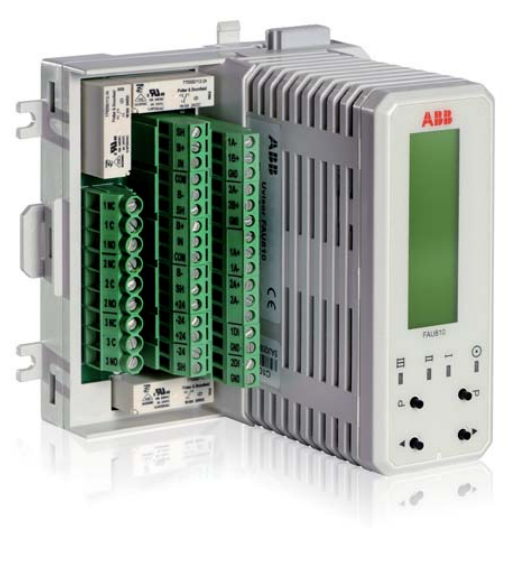
FAU810 Specifications
Flame Failure Relay Drop-Out Configurable 0.2 to 4 seconds
Flame Relay(s) Three total, each with Form C contacts
Flame Relay Contact Ratings 250 Vac, 3A, 750 VA; 220Vdc, 300 ma, 66 watts
Fault Relay Contact Ratings 250 Vac, 3A, 750 VA; 220Vdc, 300 ma, 66 watts
Analog Flame Signal Outputs Two channels of 4-20 ma signals. Each channel may independently monitor Intensity, Frequency, Quality, or AC Amplitude
Serial Data Communication Two Galvanically isolated RS-485 interfaces (fully independent for redundancy)
Serial Data Format MODBUS (default), PROFIBUS DP-V1 (selectable)
Self Checking Time Cycle Electronics shall be checked every 0.1 seconds
Ambient Temperature 0° to 60° C (32°F to 140°F), 95% non-condensing atmosphere
Case Dimensions 13 cm height, 12 cm long, 11 cm wide
Electrical Connections Screw terminals, compression type, accepting 12 to 20 wire gage
Module Mounting Din Rail Mounted
Power Consumption: 4 watts Minimum, 10 watts Maximum, Typical 6 watts
Stacking Limitation 4 modules with power entry on the end module or 7 modules with power entry on the middle module
Power supply voltage 24VDC (-25%, +20% = 18 ÷ 29VDC )
Inrush current 6A peak, 2ms settling time
Customer Interface Specifications
LCD Display Graphic LCD Display Module displaying 4 lines of 20 characters and multiple bar graphs
Programming Push-Buttons 4 (Program, Display, Up, and Down)
Status Lights 4 (Power, Flame #1, Flame #2, and Flame #3 or Fault)
Program Lock-Out Local, DIP switch select
Flame/No Flame Bypass Key None on board
Remote Programming Remote programming of functions via RS-485 link and Flame Explorer software
RS 485 2 RS-485 interfaces, one for each channel for redundancy (each interface has access to both channels)
Relay Outputs 3 – Flame #1, Flame #2, and Flame #3 or Fault
Analog Outputs Two 4-20 ma analog outputs for Trending or Monitoring of Frequency, Intensity, Quality, or AC Amplitude
4÷20 mA (R load <= 500Ω) Galvanically isolated Precision: +/-5% f.s.
Module Set-Up Menus Module Set-Up is divided into two menus, “Configuration” and ”Program”. Edit mode is protected against
occasional mistyping
Recommended ABB standard
cable:
Single Sensor scanner P/N EC-DWG-G041ELE803
Dual Sensor scanner P/N EC-DWG-GO41ELE802
Maximum distance between SF810 scanner and FAU810, Flame Analysis Unit 500 meters (1500 feet)
Compatible scanner Refer to the table below for the compatibility of the FAU810 with the associated flame scanner
Ordering code C10-12010 “FAU810 - Flame Analysis Unit, Dual Channel Complete Assembly with Dual Profibus DPV1”
Table 4 - Adapter Cable Assembly ref. ABB DWG No. C-982-0242
Assembly part no. Length Description
C10-97252 8 FT. Adapter Cable Assembly
C10-97252-25 25 FT. Adapter Cable Assembly
C10-97252-50 50 FT. Adapter Cable Assembly
C10-97252-100 100 FT. Adapter Cable Assembly
- YOKOGAWA
- Reliance
- ADVANCED
- SEW
- ProSoft
- WATLOW
- Kongsberg
- FANUC
- VSD
- DCS
- PLC
- man-machine
- Covid-19
- Energy and Gender
- Energy Access
- Renewable Integration
- Energy Subsidies
- Energy and Water
- Net zero emission
- Energy Security
- Critical Minerals
- A-B
- petroleum
- Mine scale
- Sewage treatment
- cement
- architecture
- Industrial information
- New energy
- Automobile market
- electricity
- Construction site
- HIMA
- ABB
- Rockwell
- Schneider Modicon
- Siemens
- xYCOM
- Yaskawa
- Woodward
- BOSCH Rexroth
- MOOG
- General Electric
- American NI
- Rolls-Royce
- CTI
- Honeywell
- EMERSON
- MAN
- GE
- TRICONEX
- Control Wave
- ALSTOM
- AMAT
- STUDER
- KONGSBERG
- MOTOROLA
- DANAHER MOTION
- Bentley
- Galil
- EATON
- MOLEX
- Triconex
- DEIF
- B&W
- ZYGO
- Aerotech
- DANFOSS
- KOLLMORGEN
- Beijer
- Endress+Hauser
- schneider
- Foxboro
- KB
- REXROTH
- YAMAHA
- Johnson
- Westinghouse
- WAGO
- TOSHIBA
- TEKTRONIX
- BENDER
- BMCM
- SMC
- HITACHI
- HIRSCHMANN
- XP POWER
- Baldor
- Meggitt
- SHINKAWA
- Other Brands
- UniOP
- KUKA
- IBA
- Beckhoff
- ADLINK
51
-
Beckhoff CX5020-0112 - PLC Module
-
Beckhoff CP2912-0000 - Control Panel
-
Beckhoff C6920-1047-0030 - industrial control cabinet control PC
-
BECKHOFF CX1020-0121 - CPU Module Power Supply Setup
-
Beckhoff EL6752 - DeviceNet Master EtherCAT Terminal
-
Beckhoff IP1002-B518 - Fieldbus Box Module
-
Beckhoff CP6606-0001-0020 - 7 inch Economy Panel PC incl. Connection Cable
-
Beckhoff CX5010-0111 - Controller Module
-
BECKHOFF AX2020-S62000-520 - SERVO DRIVE 5.76
-
Beckhoff EL1904 - 4-Channel Digital Input Module
-
BECKHOFF AX5201-0000 - Servo Drive
-
Beckhoff CP7201-1000-0000 - Industrial PC with Touch Screen
-
Beckhoff BK7350 - module Bus Coupler
-
BECKHOFF C6930-0010 - PLC PC Industrial PC
-
Beckhoff AX5125-0000 - Servo Amplifier
-
Beckhoff CX2100-0914 - Power Supply for External UPS for CX20xx
-
Beckhoff CP6608-1000-0010 - Control Panel
-
Beckhoff EL7221-9014 - EtherCAT Terminal, 1 Channel Motion Interface, 48 V DC
-
BECKHOFF CP2919-0000 - Multitouch Built-In Control Panel 24VDC 19"
-
BECKHOFF C6015-0010 - TWINCAT2 Single Core 1.46GHz Industrial PC
-
Beckhoff CU8803-0000 - Controller Module Transmitter
-
BECKHOFF CU1521-0000 - EtherCAT media converter
-
Beckhoff CX5140-0111 - Control Embedded PC HW 3.1 + Flash Card CX2900-0028 4GB
-
Beckhoff AX2513-B200 - Servo Amplifier Servodrive
-
Rexroth MSK061C-0600-NN-M1-UP1-NNNN - Engine Servo Motor
-
Beckhoff AM3031-0C01-0000 - Servo Motor
-
BECKHOFF CP7201-1000-0000 - Industrial PC with touch screen
-
BECKHOFF C6925-0000 - PLC Module Industrial PC
-
BECKHOFF EL5151-0021 - PLC module Encoder Interface
-
Beckhoff CX5130-0125-1001 - Module Embedded PC
-
BECKHOFF EP3356-0022 - EtherCAT Box Module
-
BECKHOFF AX5203-0000 - SERVO DRIVE
-
B&R X20IF1082 - COMMUNICATION INTERFACE MODULE POWER LINK
-
BECKHOFF EL7342 - PLC Module 2-Channel DC Motor Output
-
BECKHOFF CX8190 - Ethernet Controller
-
BECKHOFF CX2020-0120/4GB - CPU CX2100-0904 3x EL6900 EL1904 16GB RAM
-
Beckhoff CX5130-0112 - Module Embedded PC
-
Beckhoff CP7701-0001-0020 - Panel-PC Touch Panel 12" ELO Accutouch AMD ALX 500MHz
-
BECKHOFF CX5020-0111 - Embedded PC Controller
-
Beckhoff CX2040-0100 - Embedded PC HW: 4.0 + CX2100 0014 + 4GB CFast Card
-
Beckhoff CP6512-0001 0030 - Control Panel
-
beckhoff CX9020-0111-0900 - Controller Modules
-
Beckhoff IE3112 - Module Fieldbus Box
-
BECKHOFF CX8051 - PLC Module
-
BECKHOFF CX1100-0920 - module Power Supply
-
Beckhoff CP7921-1075-0000 - Control Panel
-
B&R 3NC352.6 - PLC Module
-
Beckhoff CX8095 - module Controller
-
beckhoff CX1020-0021 - CPU controller module
-
BECKHOFF BK9103 - PROFINET BUS COUPLER
-
Beckhoff C6930-0050 - Schaltschrank-Industrie-Pc Core i7-4700 CPU+FC9062 Modules
-
Beckhoff AM8013-0DH0-1001 - Servo Motor
-
BECKHOFF EPP3184-0002 - Module EtherCAT-P Box
-
BECKHOFF AM8041-0H10-0000 - servo motor
-
BECKHOFF CX1010-0100 - Embedded PC Module System
-
beckhoff CP2916-0000 - Industrial touch screen
-
Beckhoff C6110 - Industrial PC Boser HS6237
-
Beckhoff CX1010-0111 - CPU Module Setup
-
Beckhoff EL3751 - EtherCAT Terminal 1 Channel Analog Input Multifunction 24 Bit
-
BECKHOFF AX5721-0000 - Encoder Interface Card
-
Beckhoff CX1020-0122 - module Embedded PC
-
BECKHOFF CP3921-0000 - Control Panel
-
BECKHOFF CX2040-0155 - STANDARD CPU MODULE INTEL I7 2715QE 2.1GHz
-
BECKHOFF CX5020-0111 - Controller module
-
Beckhoff AX5201-0000-0200 - servo drive
-
BECKHOFF CP2921-0000 - Multi-touch built-in Control Panel with DVI/USB
-
BECKHOFF CP3907-0000 - Touch Panel
-
Beckhoff CX5120-0115 - CPU Module
-
Beckhoff KL3361 - PLC Module Oscilloscope Terminal
-
Beckhoff CX1000-0111 - Embedded PC System Combination
-
Beckhoff AM8023-0E20-0000 - Servo motor with Tramec EP75/2 Transmission
-
beckhoff am8533-2f10-0000 - servo motor
-
BECKHOFF EL5042 - EtherCAT Terminal
-
Beckhoff CX9001-1001 - PLC Module
-
BECKHOFF CX9020-0112 - Digital Module CPU Controller
-
BECKHOFF CP6709-0001-0000 - Touchpanel
-
Beckhoff 1004B2060000 - Communication Module
-
Beckhoff CX5020-0112 - PLC Controller
-
BECKHOFF EL2904 - EtherCAT Safety Input Output Module 24V
-
Beckhoff CX2040-0142 - Embedded PC Controller Module
-
BECKHOFF AM8121-0F20-0000 - SERVO MOTOR
-
Beckhoff CX9020-0112 - CPU Module
-
BECKHOFF CB3050-0008 - PCB Motherboard Board
-
Beckhoff EK1512-0010 - PLC Module EtherCAT Junction
-
BECKHOFF CX1001-0121 - Embedded PC And CPU Basic Module Controller
-
Beckhoff C6032-0070 - Industrial PC
-
Beckhoff CX1020-0122 - Module Embedded PC
-
BECKHOFF CX8010 - Controller Module
-
BECKHOFF EK1818 - Modules EtherCAT Bus Coupler
-
BECKHOFF CX5140-0155 - PLC Embedded PC
-
BECKHOFF CX1100-0910 - Power Supply Module
-
Beckhoff CX1001-0121 - CPU Module + CX1000-C00L + CX1100-0002 + CX1000-N001
-
Beckhoff CP6801-0001-0010 - Control Panel
-
BECKHOFF BK9103-1005 - Bus Coupler PROFINET
-
Beckhoff AX5203-0000-0202 - 161336 Digital Compact Servo Amplifier 2 Channel
-
BECKHOFF CX5020-0111 - Controller module
-
BECKHOFF CP7032-1031-0010 - Cp-Link Control Panel
-
Beckhoff AX5112-0000-0200 - Servo Driver
-
Beckhoff BX8000-0000 - RS232/RS485 Bus Terminal Controller | HW:1.4
-
BECKHOFF CX2020-0120 - CPU MODULE WITH CX2100 Power Supply
-
Beckhoff EL4012 - Module EtherCAT Terminal
-
BECKHOFF CP6204-0001-0030 - ECONOMY INSTALLATION CONTROL PANEL
-
Beckhoff CP6833-0001-0011 - Built-In Control Panel-Without Control Panel Monitor
-
BECKHOFF EK1521-0000 - module EtherCAT junction
-
Beckhoff EP3314-0002 - EtherCAT Compact Box M12 4x Analog Input Thermoelements
-
Beckhoff CX8090 - PLC modules Controller
-
Beckhoff AM8033-0JG0-0000 - Servo Motor
-
Beckhoff CP9035.2 - CP9035 capture card
-
Beckhoff CP7802-1241-0010 - Industrial Touchscreen 15 Inch
-
Beckhoff BX8000-0000 - Module Bus Terminal Controller
-
BECKHOFF IE1002-0000 - Junction box
-
Beckhoff AM237S-0021 - Servomotor
-
Beckhoff EL2564 - EtherCAT Terminal, 4-channel LED output, 5-48VDC, 4A, RGBW
-
BECKHOFF EL1918 - EtherCAT Terminal 8-Channel Digital Input 24V DC
-
Beckhoff CB3052-0005 - Circuitboard Motherboard
-
Beckhoff AM8023-2E11-0000 - Servomotor
-
Beckhoff CX8190 - Ethernet Controller
-
BECKHOFF EL4038 - Module EtherCAT Terminal
-
B&R 5PC910.SX01-00 - APC910 Industrial PC | i5-6440EQ 8GB
-
Beckhoff CP9030-A002 - CP-Link Karte Version: 1.1
-
BECKHOFF BK7200 - CTNET Control Techniques Bus Coupler
-
Beckhoff CP2616-0000 - Multi-Touch Touchscreen Panel for 24V DC Automation
-
BECKHOFF LOT 31 modules - PLC Module Bundle
-
BECKHOFF EJ2889-0000 - Module EtherCAT Plug-in Module
-
BECKHOFF AM8043-0H20-0000 - Servomotor
-
BECKHOFF EL3154 - module EtherCAT Terminal
-
Beckhoff C6017-0030 - Industrial PC
-
BECKHOFF CX9020-0112 - CPU Module

K-JIANG

Add: Jimei North Road, Jimei District, Xiamen, Fujian, China
Tell:+86-15305925923