
K-WANG
+086-15305925923
Service expert in industrial control field!


Product
Article
NameDescriptionContent
Adequate Inventory, Timely Service
pursuit of excellence


Ship control system
Equipment control system
Power monitoring system
Current position:
新闻动态
newS
Brand
ABB Serial Communications Module RS232
ABB Serial Communications Module RS232
ABB Serial Communications Module RS232
INTRODUCTION AND TECHNICAL DATA
PURPOSE
The Serial Communications Module provides a serial interface between the SC300E
environment and a variety of remote devices complying with the standard RS232-C. At least
one Serial Communications Module must be used in the system and fitted in Slot 10 of the
main chassis to enable communications between the system processors and the
workstations. The workstation link is used for loading the application software and monitoring
ladder and diagnostic functions. The link utilises Port 0 of the module. Additional modules can
be fitted to any other I/O slot, ‘wrong slotting’ is prevented by mechanical coding blocks (Figure
2-1 ). The system software identifies the module via a built-in hardware identifier.
Circuit triplication and voting procedures make the module single fault tolerant and front panel
indicators show Tx/Rx activity, the circuit on-line status and the health of the module.
Communications connections are via four identical ports on the front panel (Ports 0 to 3) and
these connections are duplicated on the field connector (J2) at the rear. A fifth port is for
diagnostic purposes only. The module is compatible with ‘single slot hot repair’ and the front
panel has a switch to enable a request that the module be taken off line.
This document is intended to provide a general understanding of the function of Serial
Communications Module, sufficient to enable basic maintenance operations to be effected in
the field.
Triguard SC300E
Ejector lever
User COMMports
Diagnosticport
Mechanical coding block
(Upper)
Connector J1
(Module ID)
Link LK2
(Voltage Mon)
Link LK2 Link LK4
Tx / Rx LEDs
Health LED
ON/OFF LEDs
ON/OFF Line
Request switch
Ejector lever
Connector J2
RS232 Daughterboard
Mechanical coding block
(Lower)
ASSOCIATED DOCUMENTATION
Reference No Title
008-5097 Chassis User Manual
SPECIFICATION
Model MSR04XI
Communications Serial RS232
Mictrocontroller Intel family
Communication ports: Port 0: RS232 9600 or 19200 Baud
Port 1: RS232 9600 or 19200 Baud
Port 2: RS232 9600 or 19200 Baud (see Note)
Port 3: RS232 9600 or 19200 Baud (see Note)
Diagnostic: for diagnostics purposes only Note:
Ports 2 & 3 must be set to the same Baud
rate.
rate. Isolation Ports 0 to 3, 1kV
Indicators Tx, Rx, Health, 3 x On Line
Hot repair procedure Single slot
Module power consumption 3.5W
Overall size (mm)
Overall size (inches)
400(9U)H x 397L x 28W
15.75H x 15.63L x 1.1W
Weight 1.3kg
Triguard SC300E
ENVIRONMENTAL SPECIFICATIONS
The maximum ambient temperature measured at the hottest point within the Triguard system
shall not be greater than 60 degrees centigrade.
Temperature operating: +5°C to +60°C
Temperature storage: -25°C to +70°C
Humidity 5% to 95% non-condensing at ambient <40°C
EMC/RFI Immunity Tested and certified to IEC 1131-Part 2 1994
Vibration/Shock Tested and certified to IEC 1131-Part 2 1994
Certification:
General Certification: Ref. SC300E Product Guide (ref 008-5209)
TRANSPORT AND HANDLING
The MSR04XI module must be transported and stored in its original packing material which
should be retained for this purpose.
TECHNICAL DESCRIPTION
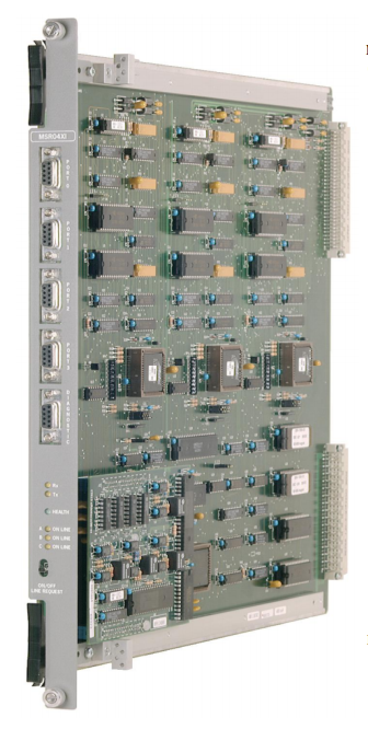
PHYSICAL
The Serial Communications Module is a 9U high PCB with integral front panel and front and
rear connectors; a plug-in daughter board carries the RS232 interface circuits. Figure 1-1
shows the general layout, location of the connectors and front panel components.
Mechanical coding blocks
All Input/Output modules carry two mechanical coding blocks equipped with pins which mate
with holes in corresponding blocks in the chassis and prevent the module being inserted into
the wrong slot. The pins in the module blocks are factory installed in a pattern determined by
the module and corresponding set screws are removed from the chassis coding blocks to
enable fitting. Unused holes are plugged with set screws. The chassis mechanical coding
block configuration for this module is shown in Figure 2-1 .
Triguard SC300E
On the lower section of the PCB are three further links, LK2, LK3 and LK4, located and
configured as follows:
LK2 (2-pin) located approximately 220mm down from the top of the module and 110mm in from
the front face, used in the voltage monitoring circuit, always fitted.
LK3 (3-pin) located beneath the plug in daughterboard. Used for 3-2-1-or 3-2-0 operation,
factory fitted hard wired, all pins linked for 3-2-1 mode.
LK4 (3-pin) located approximately 250mm down from the top of the module and 220mm from
the front face, used for the daughterboard clock speed setting, pins 1 and 2 linked.
Table 2-1. Default link settings
Link Default setting
LK1 (3 off x 3 pin) Links not fitted
LK2 (3 off x 8 pin) Fitted
LK2 (2 pin) Fitted
LK3 (3 pin) Hard wired (all pins linked)
LK4 (3 pin) Fitted (pins 1 & 2 linked
EXTERNAL CONNECTIONS
Pinouts and signals for front panel connectors J4 to J6 through to J2 backplane are given in
Table 2-2.
Is your interface DTE (data terminal equipment) or DCE (data communications equipment)?:
The point of reference for all signals is the terminal (or PC).
Transmit and receive leads (2 or 3) can be reversed depending on the use of the equipment,
either DTE or DCE.
THEORY OF OPERATION
Triplicated data enters and leaves the module (Figure 2-3 ) via the chassis backplane
connector J1 and is isolated from the MPP by bus transceivers. Data for transmission is
loaded into dual port RAM in each of the three circuit branches and is voted 2-oo-3 before being
passed to the USARTs on the daughter board where it is serialised and sent to the appropriate
communications port.
Data received at the ports is converted to parallel form by the USART and written to dual port
RAM in each branch, the data is accompanied by information about the status of the ports and
the embedded microprocessor. The dual port memory is then read by the MPP via a second
set of transceivers.
The four communications ports are configured to run in full duplex mode using an RS232
interface and having a maximum rate of 19200 Baud. The communications ports are isolated
from the module circuits by opto-isolators and connected to field connector J2 at the rear of the
module. The ports are capable of powering modems or line drivers for transmission over long
distances.
Power for the module circuits is derived from the dual redundant SC300E power supply units,
individual auctioneering and regulating circuits supplying various logic areas. The
communications port opto-isolators and interfaces also have separate supplies.
- YOKOGAWA
- Reliance
- ADVANCED
- SEW
- ProSoft
- WATLOW
- Kongsberg
- FANUC
- VSD
- DCS
- PLC
- man-machine
- Covid-19
- Energy and Gender
- Energy Access
- Renewable Integration
- Energy Subsidies
- Energy and Water
- Net zero emission
- Energy Security
- Critical Minerals
- A-B
- petroleum
- Mine scale
- Sewage treatment
- cement
- architecture
- Industrial information
- New energy
- Automobile market
- electricity
- Construction site
- HIMA
- ABB
- Rockwell
- Schneider Modicon
- Siemens
- xYCOM
- Yaskawa
- Woodward
- BOSCH Rexroth
- MOOG
- General Electric
- American NI
- Rolls-Royce
- CTI
- Honeywell
- EMERSON
- MAN
- GE
- TRICONEX
- Control Wave
- ALSTOM
- AMAT
- STUDER
- KONGSBERG
- MOTOROLA
- DANAHER MOTION
- Bentley
- Galil
- EATON
- MOLEX
- Triconex
- DEIF
- B&W
- ZYGO
- Aerotech
- DANFOSS
- KOLLMORGEN
- Beijer
- Endress+Hauser
- schneider
- Foxboro
- KB
- REXROTH
- YAMAHA
- Johnson
- Westinghouse
- WAGO
- TOSHIBA
- TEKTRONIX
- BENDER
- BMCM
- SMC
- HITACHI
- HIRSCHMANN
- XP POWER
- Baldor
- Meggitt
- SHINKAWA
- Other Brands
- UniOP
- KUKA
- IBA
- Beckhoff
- ADLINK
51
-
Beckhoff EP9224-0037 - 4-Channel Power Distribution Box EtherCAT
-
Beckhoff CX2900-0026 - Solid State Flash Memory Card 20GB CFast
-
Beckhoff BK7500 - SERCOS Interface Fieldbus Bus Coupler Terminal
-
Beckhoff Ep2328-0002 - 4-Channel Input 4-Channel Output EtherCAT Box IP67
-
Beckhoff CX1020-0111 - Controller Kit Combo Interface Modules
-
B&R X20AI2237 - X20 System Analog Input Interface Module
-
Beckhoff CP2221-0010 - Multi-Touch Built-In Panel PC Touchscreen
-
Beckhoff CX1500-M310 - Fieldbus Master Interface Module 24V
-
Beckhoff CX2100-0904 - Power Charging Module Smart UPS Extension
-
Beckhoff CP3918-0000 - Multi-Touch Control Panel 18.5-Inch Monitor
-
Beckhoff CP2915-0000 - 15-Inch Multi-Touch Built-In Control Panel
-
Beckhoff CP7037-1027 - HMI Industrial Control Panel Built-In PC
-
Beckhoff EL3152 - 2-Channel Analog Input Terminal 4-20mA EtherCAT
-
Beckhoff CP6607-0000-0020 - 5.7-Inch Built-In Panel PC HMI Touch
-
Beckhoff EJ1809-0000 - 16-Channel Digital Input Pluggable Signal Level Terminal
-
Beckhoff AM8563-0N10-0000 - Synchronous Servo Motor
-
Beckhoff AX2006-S60600-520 - Compact Servo Drive Inverter
-
Beckhoff AM8053-0K20-0000 - Servo Motor with Planetary Gearbox AG3210
-
Beckhoff AM8042-0FH1-0000 - Synchronous Servo Motor
-
Rexroth R911338600 - IndraControl V HMI Terminal Beckhoff PCI Card FC9002
-
Beckhoff AX5125-0000 - 3 Phase Industrial Servo Drive 1000Hz
-
Beckhoff EP2328-0002 - 4-Channel Digital Input 4-Channel Output EtherCAT Box
-
B&R 7CP476-02 - System 2005 RTD CPU Module 3IF681.86 Interface
-
Beckhoff AX8620-0000-0000 - Power Supply Module Axis Drive System
-
Beckhoff CX1010-0111 - PLC Module CPU Controller 24V
-
Beckhoff AM8043-0H10-0000 - Synchronous Servo Motor
-
Beckhoff C6240-1009 - Control Cabinet Industrial PC Mainframe
-
Beckhoff BX8000-0000 - Bus Terminal Controller HW 4.4 Standalone
-
Beckhoff CP7721-1089-0020 - 12.1-Inch Touch Screen HMI Panel PC
-
Beckhoff CP7132-0001 - Industrial Built-In Panel PC Screen
-
Beckhoff CP2912-0010 - Multi-Touch Built-In Control Panel Display
-
Beckhoff CP2915-0000 - 15-Inch Multi-Touch Built-In Control Panel
-
Beckhoff AM8532-1EN0-0000 - Synchronous Servo Motor
-
Beckhoff AX5203-0000 - 2-Channel Digital Compact Servo Drive
-
Beckhoff CX2020-0141 - Embedded PC Core CPU Module
-
Beckhoff CP6832-0002-0010 - Built-In Industrial Control Panel Display
-
Beckhoff CX5020-0112 - Embedded PC CPU Control Module
-
Beckhoff CX5140-0175 - 4GB Embedded PC CPU Unit 24V
-
Beckhoff EL3681-0030 - Digital Multimeter Calibration Terminal EtherCAT
-
Beckhoff CP7201-1000-0000 - Industrial PC Touch Screen HMI Monitor
-
Beckhoff CP7232-1001-0000 - Industrial Panel PC Touch Screen
-
Beckhoff C6930-1032-0040 - Control Cabinet Industrial PC System
-
Beckhoff AX5125-0000 - 3 Phase Industrial Servo Drive 1000Hz
-
Beckhoff CP3916-1424-0000 - Multi-Touch Built-In Control Panel
-
B&R 1900071142 - Lemoine Fieldbus Communication Interface Module
-
Beckhoff EL2872 - 16-Channel Ribbon Cable Digital Output Terminal
-
Beckhoff CX2030-0120 - Embedded PC CPU Base Module Controller
-
Beckhoff CP3919-0000 - 19-Inch Multi-Touch Control Panel Touchscreen
-
Beckhoff AX5101-0000-0202 - Servo Driver Compact Intelligent Drive 180V
-
Beckhoff CX5130-0135 - Embedded PC Controller Module
-
Beckhoff CP3719-1061-0010 - Multi-Touch Panel PC Outer Housing Enclosure
-
Beckhoff CP3919-1033-0000 - 19-Inch Touch Industrial Panel Keyboard
-
Beckhoff CX5020-0111 - Embedded PC PLC CPU Module
-
Beckhoff FC5102-0000 - 2-Channel CANopen PCI Control Board Card
-
Beckhoff CX9001-1101 - Embedded PC CPU Network I/O System Module
-
Beckhoff CX1100-0920 - Smart Position Sensor Interface Module
-
B&R 4P3040.01-490 - Operator Panel PLC Interface Communication Module
-
Beckhoff CP2612-0000 - Dual-Touch Built-In Panel PC HMI
-
Beckhoff CP7002-1043-0010 - Touchscreen Display HMI Panel Terminal
-
Beckhoff CX9020-0115 - Embedded PC Controller Module
-
Beckhoff CX5140-0155 - 4GB Embedded PC CPU Module Die Industry
-
B&R 7DI435.7 - System 2005 Universal Digital Input Output Module
-
Bihl+Wiedemann BWU1568 - AS-i Master to Profibus Gateway Module
-
Beckhoff C6920-0070 - Control Cabinet Industrial PC 8GB Win 10
-
B&R X20AI2322 - 2-Channel Temperature Analog Input Module
-
Beckhoff CP2912-0000 - 12-Inch Touchscreen Display Monitor Screen
-
Beckhoff CP6022-1001-0010 - 15-Inch Built-In Control Panel
-
Beckhoff AM8031-0D10-0000 - Synchronous Servo Motor
-
Beckhoff CX5010-0111 - Embedded PC Controller CPU Module
-
Beckhoff CP7232-1000-0000 - Industrial Panel PC Touch Display Screen
-
Beckhoff CP7802-0011-0000 - 15-Inch Industrial Touchscreen Control Panel
-
Beckhoff C6320 - Control Cabinet Industrial PC
-
Beckhoff CX1030-0012 - Basic CPU Module Windows CE 6.0
-
Beckhoff CP2919-0000 - Installation Multi-Touch Control Panel
-
Beckhoff CX1020-0000 - Controller Set Stack System Pack
-
B&R 3DO480.6 - System 2005 Digital Output Module
-
Beckhoff EL3101 - 1-Channel Analog Input Terminal Differential +/-10V
-
Beckhoff AX8108-0200-0000 - Axis Feed Module Servo Drive
-
Beckhoff CP7802-1241-0010 - 15-Inch Industrial Touchscreen Control Panel
-
Beckhoff FC2002-0000 - 2-Channel Lightbus Data Acquisition PCI Card
-
Beckhoff CX5120-0155 - 2GB Embedded PC Intel Atom Controller
-
Beckhoff Cx9020-0111 - 1GB Basic CPU Module Embedded PC
-
Beckhoff CP6901-0001-0000 - 12-Inch Economy Built-In Control Panel
-
Beckhoff CX9020-0111 - Embedded PC CPU Basic Module
-
Beckhoff CX5130-0100 - 4GB Embedded PC CPU Module
-
Beckhoff CP2715-0010 - Multi-Touch Built-In Panel PC
-
Beckhoff CX2033-0175 - Embedded PC CPU Module Core i7
-
Beckhoff CP7201-1000-0000 - 12-Inch Touchscreen Panel PC AMAT Green Box
-
Beckhoff EL4038 - 8-Channel Analog Output Terminal 0-10V EtherCAT
-
Beckhoff CP6802-0000-0000 - Built-In Control Panel HMI Screen
-
Beckhoff AM8042-0F21-0000 - Synchronous Servo Motor
-
Beckhoff CX5120-0141 - Embedded PC Basic Controller Module
-
Beckhoff C6930-0050 - Control Cabinet Industrial PC System
-
Beckhoff CP6831-0002-0000 - Built-In Industrial Control Panel
-
Beckhoff CP6919-0001-0000 - Built-In Control Panel Display Unit
-
Beckhoff CP7201-1019-0030 - Built-In Panel PC HMI Monitor Screen
-
Beckhoff CP6809-0001-0000 - 6.5-Inch Touch Panel ELO Accutouch HMI
-
Beckhoff CX1020-0000 - Control Kit Combo Stack Units
-
Beckhoff cp3918-1012-0000 - 18.5-Inch Multi-Touch Control Panel
-
Beckhoff CX5140-0123 - 4GB Embedded PC CPU Module
-
Beckhoff C3230TP - Industrial PC Rackmount Workstation
-
Beckhoff CP6801-1006-0010 - Touch Panel HMI Display Unit
-
Beckhoff CX8010 - Embedded PC Controller Module
-
Beckhoff CP7011-0001 - Control Panel CRT Operator Pendant Monitor HMI
-
Beckhoff CX1010-0111 - Embedded PC CPU PLC Module 24V
-
Beckhoff CP2915-0000 - 15-Inch Multi-Touch Built-In Control Panel
-
Beckhoff CP7802 - Industrial Touch Screen Control Panel Monitor
-
Siemens 6AV7452-1AB00-0FB0 - Industrial PC Panel 877 Beckhoff PCI Cards
-
Beckhoff CP2612-0000 - Dual-Touch Integrated Panel Monitor Screen
-
Beckhoff CX5140-0175 - Embedded PC Core Controller
-
Beckhoff Cp6202-0001-0010 - Economy Built-In Panel PC System
-
Beckhoff C6320-0010 - Control Cabinet Industrial PC Unit
-
Beckhoff CP2919-0000 - Multi-Touch Built-In Control Panel Screen
-
Beckhoff CX9020-0111 - Embedded PC CPU Controller Module
-
B&R 3BP151.41 - System 2005 Backplane Base Module
-
Siemens 6AV7452-1AB00-0FB0 - Panel PC 877 with Beckhoff Communication Cards FC3101 FC7501
-
Beckhoff CX9001-1101 - Embedded PC System Fieldbus Module Bundle
-
Beckhoff CX1001-0122 - CPU Module PLC Controller 128MB RAM
-
Beckhoff CX5130-0175 - Embedded PC CPU Module Intel Atom Storage Card
-
Beckhoff C6140 - Industrial PC Tower Casing Pent 4 System
-
Beckhoff CX5020-0120 - Embedded PC Controller Core Module
-
Beckhoff C6017-0010 - Ultra-Compact Industrial PC
-
Beckhoff CP6809-0000-0000 - 6.5-Inch Industrial Panel Control Display
-
Beckhoff AX5021-0000-0000 - Brake Chopper Module Axis System
-
Beckhoff AM8031-0D10-0000 - Synchronous Servo Motor
-
Beckhoff CX8010 - Embedded PC Microcontroller Module
-
Beckhoff CP6202-1070-0070 - Built-In Panel PC HMI Touchscreen
-
Beckhoff C6920-0000 - Control Cabinet Industrial PC Module

K-JIANG

Add: Jimei North Road, Jimei District, Xiamen, Fujian, China
Tell:+86-15305925923