
K-WANG


Triconex 3624 Digital Output Module
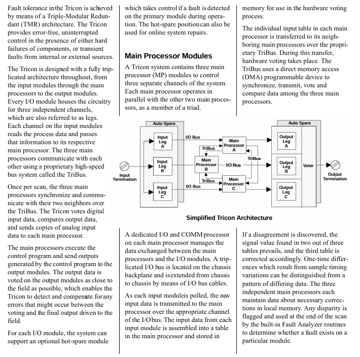
Tricon controller: It adopts the third mock examination redundancy (TMR) architecture to achieve fault tolerance, integrates three independent parallel control systems and comprehensive diagnostic functions, ensures no single point of failure through the "three out of two" voting mechanism, and achieves high integrity, error free, and uninterrupted process operation.
TMR architecture details: Three identical channels independently and parallelly execute control programs, digital I/O is verified through dedicated software and hardware voting, and analog input adopts median selection; The channels are isolated from each other, and a single channel failure does not affect other channels. The faulty module can be replaced online.
Triconex 3624 Digital Output Module
Overview of the Core of Tricon Fault Tolerant Control System
Core Definition and Architecture
Fault Tolerant Control: capable of identifying and compensating for faulty control units, allowing for repairs without interrupting processes, suitable for critical process applications that require high safety and availability.
Tricon controller: It adopts the third mock examination redundancy (TMR) architecture to achieve fault tolerance, integrates three independent parallel control systems and comprehensive diagnostic functions, ensures no single point of failure through the "three out of two" voting mechanism, and achieves high integrity, error free, and uninterrupted process operation.
TMR architecture details: Three identical channels independently and parallelly execute control programs, digital I/O is verified through dedicated software and hardware voting, and analog input adopts median selection; The channels are isolated from each other, and a single channel failure does not affect other channels. The faulty module can be replaced online.
Key Features
No single point of failure; Support 3, 2, or 1 main processor to run until shutdown; Fully implemented and transparent triple transformation; Comprehensive system diagnosis; Complete I/O module series; Provide dual I/O and single I/O modules for safety critical and limited availability requirements; Remote I/O can be up to 7.5 miles (12 kilometers) away from the main processor; Support simple online module maintenance; Has extremely high reliability and availability.
Typical application scenarios
Emergency Safety Shutdown (ESD): protects key units such as refineries and petrochemical/chemical plants, monitors parameters such as pressure and feed rate, avoids false tripping of traditional relay systems, has sensor integrity detection, integrated shutdown and control functions, and can be connected to monitoring data highways.
Boiler flame safety: Integrating boiler protection, start stop safety interlock, and flame safety functions, replacing traditional discrete components, improving resource utilization, and maintaining or exceeding the safety of electromechanical protection systems.
Turbine control system: realizes the control and protection of gas/steam turbines, integrates speed control and start stop sequence, avoids unplanned shutdowns through I/O module hot standby, and automatically activates the standby module in case of faults.
Marine fire and gas protection: supports online replacement of faulty modules, built-in diagnostic management module, wiring and sensor faults, simulated fire and gas detectors can be directly connected, replacing traditional fire and gas panels, saving space and ensuring high safety and availability.
Detailed specifications of 3624 digital output module
Module basic information
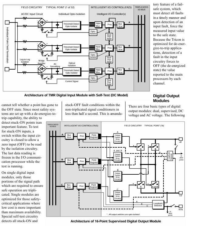
Type: TMR (the third mock examination redundancy), with supervised function.
Nominal voltage: 24 VDC.
Output points: 16 points, shared.
Electrical parameters
Voltage range: 16-30 VDC, maximum voltage 36 VDC.
Voltage drop: Typical value<1.5 VDC.
Power module load:<10 watts.
Current rating: maximum 0.7 A per point, maximum surge current of 4.8 A within 10 ms.
Minimum required load: 30 mA.
Load leakage current: maximum 4 mA.
Point isolation: minimum 1500 VDC.
Fuse: None (self-protection).
Function and Diagnosis
Monitoring function: By using voltage and current loop circuits, combined with online diagnosis, the output switch, on-site circuit, and load status can be verified, and faults such as on-site power loss/fuse melting, load open circuit/loss, load misoperation short circuit, load power-off short circuit, etc. can be detected; The POWER alarm is activated when the on-site voltage cannot be detected, and the LOAD alarm is activated when the load cannot be detected.
Module status diagnosis: equipped with PASS (module passes self-test), FAILT (module fault), ACTION (module activation) indicator lights, with ON/OFF status indicator lights at each point, color code Turquoise Green.
Compatibility and Installation
Supporting hot standby modules requires a separate external terminal panel (ETP) and cable interface with the Tricon backplane; The module adopts a mechanical key control design to prevent accidental installation into the wrong slot; On site wiring requires connecting the on-site power supply to each output point of the on-site terminal, with the output designed to provide current to the on-site equipment.
System configuration and hardware components
System Composition
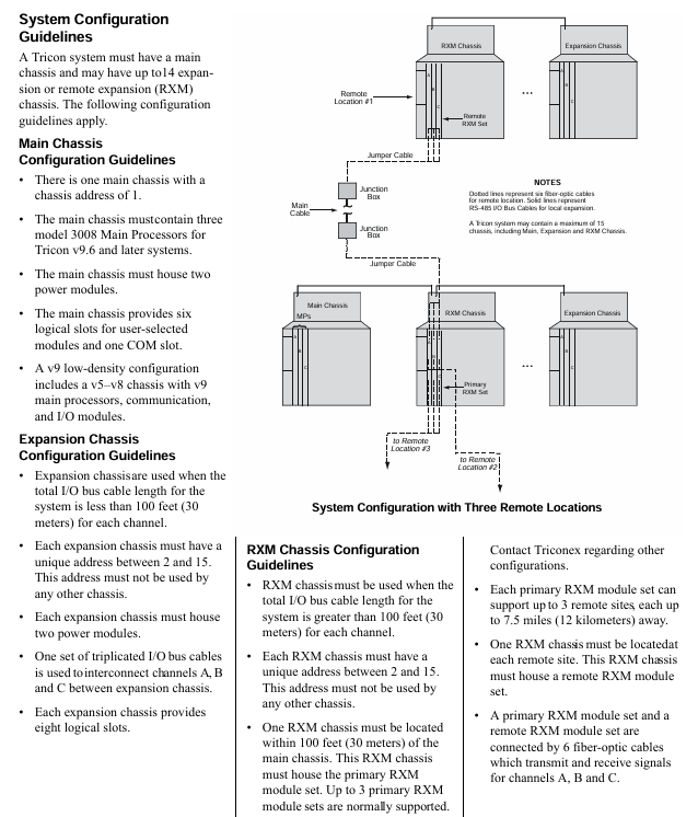
Composed of one main chassis and up to 14 extended or remote extended (RXM) chassis, up to 15 chassis can support 118 I/O modules and communication modules, and can connect OPC clients, Modbus devices, other Tricon controllers, Ethernet (802.3) external host applications, and Foxboro, Honeywell DCS.
Chassis Layout and Configuration Rules
Main Chassis: There are two power modules on the left side and three main processors on the right side. The remaining space is divided into six logical slots for I/O and communication modules, as well as one COM slot without a hot spare position. Each logical slot contains two physical spaces (active module and optional hot spare module); Address 1 requires three 3008 model main processors (Tricon v9.6 and above) and two power modules.
Expand Chassis: The layout is similar to the main Chassis, but provides 8 logical slots for I/O modules; The length of the I/O bus cable is usually up to 100 feet (30 meters), and can reach up to 1000 feet (300 meters) in restricted applications. The address needs to be between 2-15 and unique, requiring two power modules connected to channels A, B, and C through a triple I/O bus cable.
RXM Chassis: Used in scenarios where the total length of I/O bus cables exceeds 100 feet (30 meters), with addresses 2-15 and unique; An RXM Chassis needs to be located within 100 feet (30 meters) of the main Chassis, with built-in main RXM module groups (usually supporting 3 groups), each group can support 3 remote sites, with each site up to 7.5 miles (12 kilometers) away from the main site. Remote sites require RXM Chassis and remote RXM module groups, with the main and remote RXM module groups connected by 6 fiber optic cables; Provide 6 I/O module logic slots and 1 blank slot, requiring two power modules that can be connected to the local expansion Chassis via I/O bus cables.
Core hardware component specifications
Power module: each Chassis is equipped with two, and any module can operate under full load and rated temperature, supporting online replacement; Convert the line power supply to a DC power supply suitable for the Tricon module, with an input of at least 240 watts per power module; The alarm contact will activate when the module is missing, there is a conflict between hardware and control program logic configuration, the module is faulty, the main processor detects a system fault, the main power supply of the power module is faulty, or there is a warning of "low battery" or "over temperature" in the power module; There are multiple models available, such as 8310 (120 VAC/VDC), 8311 (24 VDC), 8312 (230 VAC), with an output power of 175 watts (at 140 ° F/60 ° C), an output voltage of 6.5 VDC ± 1%, a maximum output current of 27 A (in 140 ° F/60 ° C environment), input and output isolation>1000 VAC or 1500 VDC, and an over temperature sensor triggered when the internal temperature is>181 ° F (83 ° C), usually corresponding to an ambient temperature of 140 ° F (60 ° C) or above.
Main processor module (Model 3008): Used in Tricon v9.6 and above systems, each system requires 3 main Chassis modules, which independently communicate with the I/O subsystem and execute user control programs; Includes Motorola MPC860 32-bit 50 MHz microprocessor, 16 MB DRAM (without battery backup), 32 KB SRAM (battery backup), 6 MB Flash PROM; TriBus communication speed of 25 Mbps, 32-bit CRC protection, 32-bit DMA and complete isolation; The I/O bus and communication bus processors are Motorola MPC860 32-bit 50 MHz; Equipped with multiple status indicator lights such as PASS, FAULT, and ACTION; Support sequence of events (SOE) and time synchronization, protect user programs and maintain variable integrity for at least 6 months during power outages, powered by dual power modules and main Chassis power rails.
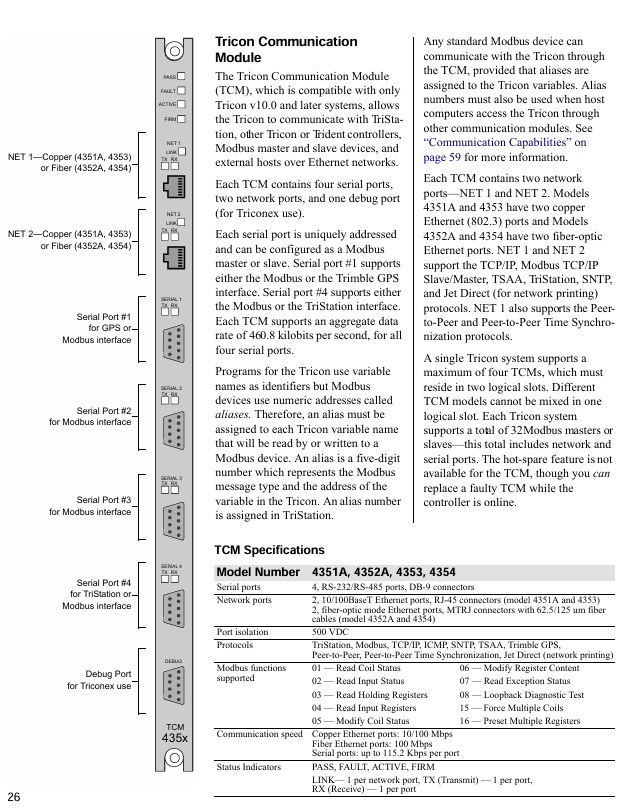
Communication module: Multiple types meet different communication needs, such as the Tricon Communication Module (TCM) that supports communication with Modbus devices TriStation PC、 Communication between network printers, other Tricon controllers, and Ethernet devices, including 4 serial ports, 2 network ports, and 1 debugging port. A single system can support up to 4 ports and should be located in two logical slots; Enhanced Intelligent Communication Module (EICM) supports RS-232/422/485 serial communication, including 4 serial ports and 1 parallel port. A single system can support up to 2 ports, which need to be located in one logical slot; The Network Communication Module (NCM) supports Ethernet (802.3) communication, including 2 BNC interfaces and 1 RS-232 serial port, supports OPC Server and TSAA protocols, and NCMG supports GPS time synchronization; The Safety Manager Module (SMM) connects Tricon to Honeywell TDC 3000 UCN; Hiway interface module (HIM) connects Tricon with Honeywell TDC 3000 Hiway gateway and LCN; Advanced Communication Module (ACM) connects Tricon with Foxboro I/A Series DCS.
Remote Expansion Module (RXM): Supports I/O modules located several kilometers away from the main Chassis, consisting of three identical modules, serving as relays and extenders for the Tricon I/O bus, providing ground loop isolation; There are multimode fiber (4200-3 main, 4201-3 remote, maximum distance 1.2 miles/2 kilometers) and single-mode fiber (4210-3 main, 4211-3 remote, maximum distance 7.5 miles/12 kilometers) models, with a communication speed of 375 kbps and indicator lights such as PASS, FAULT, and ACTION.
On site terminal options
Terminal product type
External Terminal Panel (ETP): a passive printed circuit board that facilitates on-site wiring, transmits signals between the site and I/O modules, supports I/O module replacement without interfering with on-site wiring; The on-site signals can be collected in a separate enclosure up to 99 feet (30 meters) away from Tricon; The standard panel includes terminal blocks, resistors, fuses, and other components, suitable for lines 24-12 (0.3-2.1mm ²), with some having current limiting resistors or fuses with fuse indication; There are also basic panels (including connectors and terminal blocks only, users need to equip other components themselves), hazardous area (non flammable) panels (suitable for Zone 2, Class 1, Division 2, certified by T Ü V), panels with intermediate relays (suitable for load current>2A or voltage>115 VAC scenarios), digital input bypass panels (32 pre wired switches, including master key switch and redundant 24 VDC power terminals), panels with signal conditioners (supporting RTD, thermocouple, 4-20 mA transmitter, 16 points/panel, compatible with 1-5V output signal conditioners) and other types.
Faned Out Cables: A low-cost alternative to ETP, with one end connected to a Tricon backplane and the other end having 50 labeled 22 wires with pin numbers, suitable only for digital I/O modules. The standard length is 10 feet (3 meters) and can be customized up to 99 feet (30 meters). The last two digits of the model indicate the length (feet).
Terminal configuration and protection
Configuration options: Non common ground terminal (each point can be connected to an independent power supply), common ground terminal (multiple points share one power supply, can be connected to a common ground group of 8 or 16 points); Analog signals can be connected to 3-wire transmitter inputs, voltage inputs, or current inputs; The thermocouple terminal provides a cold junction temperature sensor, the 3706A model's fuse detection relies on the terminal panel, and the 3708E model can be configured through TriStation.
Overcurrent protection: Non basic terminal panels are self protected through single point/on-site power fuses, series resistors, digital and analog output modules; The basic terminal panel requires users to equip themselves with overcurrent protection components.
Module and Terminal Matching Table: The document provides a detailed table that lists various terminal panel models (common ground, non common ground, basic, non flammable, fan out cable, bypass panel, ERT loopback cable/panel) corresponding to each I/O module (such as digital input, digital output, pulse input, relay output, analog input, analog output, thermocouple input module, etc.). For example, the common terminal panel model corresponding to the 3624 digital output module (24 VDC, 16 points, TMR monitoring type) is 9662-610, the basic terminal panel model is 9653-610, the non flammable terminal panel model is 9671-610, and the fan out cable model is 9101-010.
Terminal panel dimensions: The document lists the width (horizontally along the DIN rail), length (vertically along the DIN rail), and height (away from the DIN rail) dimensions of each model of terminal panel, in inches and centimeters. For example, the 9551-110 panel has a width of 3 inches (7.62 centimeters), length of 5 inches (12.7 centimeters), and height of 4.25 inches (10.795 centimeters).
Communication capability
Communication range and supported objects: Tricon can communicate with Modbus master-slave devices, Foxboro I/A Series Nodebus, Honeywell UCN, Honeywell Data Hiway and LCN, Ethernet (802.3) external hosts, other Tricon controllers (peer-to-peer networks), TriStation PC, OPC Server through communication modules.
Details of Key Communication Module Functions
TCM (Tricon Communication Module): Only compatible with Tricon v10.0 and above, supporting communication with TriStation, other Tricon/Rident controllers, Modbus master-slave devices, and Ethernet external hosts; 4 serial ports (configurable as Modbus master/slave, serial port 1 supports Modbus or Trimble GPS, serial port 4 supports Modbus or TriStation, total data rate 460.8 kbps), 2 network ports (4351A/4353 is copper Ethernet, 4352A/4354 is fiber Ethernet, supports TCP/IP, Modbus TCP/IP and other protocols, network port 1 also supports peer-to-peer and peer-to-peer time synchronization protocols); A maximum of 4 units per system, located in two logical slots, do not support hot standby but can be replaced online; The Tricon variable needs to be assigned a 5-digit alias (representing the Modbus message type and variable address) to communicate with Modbus devices.
EICM (Enhanced Intelligent Communication Module, Model 4119A): Supports Modbus master-slave devices TriStation、 Printer communication; 4 serial ports (configurable as Modbus master/slave, supporting RS-232/422/485, up to 7 Modbus master stations per Chassis), 1 parallel port (Centronics compatible); A maximum of 2 units per system, located in one logical slot, do not support hot standby but can be replaced online; The total data rate is 57.6 kbps, Modbus supports RTU or ASCII mode, and Tricon variables need to be assigned aliases.
NCM (Network Communication Module, Model 4329/4329G): Supports Ethernet (802.3) communication at a speed of 10 Mbps, and NCMG supports GPS time synchronization; 2 BNC interfaces (RG58 50 ohm thin cable), 2 external transceiver interfaces (15 pin D-type), and 1 RS-232 serial port; Port 1 supports peer-to-peer and time synchronization protocols (only for Tricon secure networks), while Port 2 supports open networks (TriStation, SOE, OPC Server, etc.); A single logical slot can accommodate 2, working independently and not as a hot backup; External hosts need to access Tricon variables through aliases, which can be extended to a distance of 2.5 miles (4000 meters) through repeaters and standard cables.
SMM (Safety Manager Module, Model 4409): Connect Tricon to Honeywell TDC 3000 UCN as a safety node on the UCN, transmit process information at full network rate, and transmit Tricon alias data and diagnostic information to the operation station in a format familiar to Honeywell operators; Support critical I/O point processing, alarm processing and propagation, alias data reading and writing, Tricon diagnostic reading, write protection, DCS time synchronization, peer-to-peer communication, event sequence transmission, and hot standby functions; 2 isolated UCN ports, data rate 5 MB/s, power load<20 watts, isolated 500 VDC, equipped with multiple status indicator lights.
HIM (Hiway Interface Module, Model 4509): connects Tricon with Honeywell TDC 3000 (via Hiway gateway and LCN) or TDC 2000 (via Data Hiway), supporting communication between high-level devices on LCN/Data Hiway and Tricon; 2 isolated Data Hiway channels, baud rate of 250 kbps, equivalent to 4 extended Data Hiway port addresses, providing 8 Hiway addresses, data refresh<0.5 seconds; Support hot standby, power load<10 watts, isolated 500 VDC, with multiple status indicator lights.
ACM (Advanced Communication Module, Model 4609): connects Tricon with Foxboro I/A Series system as a secure node on Nodebus, transmitting process information at full network rate, and transferring Tricon alias data and diagnostic information to the operation station in a format familiar to Foxboro operators; Support critical I/O point processing, alarm processing and propagation, alias data read and write, Tricon diagnostic read, write protection, I/A Series time synchronization, and hot standby function; BNC supports TriStation, TSAA protocol, and user applications; Multiple ports (BNC, 15 pin D-type AUI, 9-pin RS-423 Nodebus control port, etc.), some ports have a speed of 10 Mbps, the Nodebus control port is 2400 baud, the power load is 20 watts, isolated 500 VDC, and equipped with multiple status indicator lights.
Communication Protocol and Application
Support agreement: TriStation、Modbus(RTU/ASCII/TCP)、TCP/IP、ICMP、SNTP、TSAA、Trimble GPS、 Peer to Peer, peer-to-peer time synchronization, Jet Direct (network printing), etc.
Triconex protocol: Peer to peer protocol (exchanging security and process information between Tricons), time synchronization protocol (maintaining Tricon time consistency in the network), TriStation protocol (master-slave communication between TriStation PC and Tricon, one slave per communication), TSAA protocol (master-slave communication between external hosts and Tricon, used for developing control or monitoring applications).
Triconex applications: TriStation 1131 (for developing, testing, and monitoring Tricon applications), Event Sequence (SOE, for retrieving Tricon events in the network for maintenance and downtime analysis), Enhanced Diagnostic Monitor (for monitoring Tricon hardware and application status), DDE Server (for allowing Windows DDE clients such as Excel to read and write Tricon alias data), OPC Server for Triconex (for allowing OPC clients to read and write Tricon program variables, some modules rely on external Matrikon OPC Server, and some models will have embedded OPC Server).
Network redundancy and configuration rules
Module/Media Redundancy: Install two communication modules (TCM/NCM/ACM) in the same logical slot and connect network nodes with two sets of cables to address issues such as cable breakage and port failures.
External host redundancy: The backup external host is connected to the network, and in the event of a primary host failure, the control program can be restarted on the backup host. All Triconex applications can be loaded onto the primary and backup hosts.
Configuration rule: TriStation PC needs to communicate with Tricon through TCM/EICM/NCM/ACM, and at least one such module needs to be installed in the main Chassis or Chassis 2; Some modules (such as EICM, ACM) have a limit on the number of logical slots, and some modules (such as NCM, TCM) cannot coexist in the same system; If Chassis 2 is equipped with a communication module, it requires an I/O COMM cable (9001 model) instead of a standard I/O bus cable to directly connect to the main Chassis. Chassis 2 can be an I/O expansion Chassis or a main RXM Chassis.
- YOKOGAWA
- Reliance
- ADVANCED
- SEW
- ProSoft
- WATLOW
- Kongsberg
- FANUC
- VSD
- DCS
- PLC
- man-machine
- Covid-19
- Energy and Gender
- Energy Access
- Renewable Integration
- Energy Subsidies
- Energy and Water
- Net zero emission
- Energy Security
- Critical Minerals
- A-B
- petroleum
- Mine scale
- Sewage treatment
- cement
- architecture
- Industrial information
- New energy
- Automobile market
- electricity
- Construction site
- HIMA
- ABB
- Rockwell
- Schneider Modicon
- Siemens
- xYCOM
- Yaskawa
- Woodward
- BOSCH Rexroth
- MOOG
- General Electric
- American NI
- Rolls-Royce
- CTI
- Honeywell
- EMERSON
- MAN
- GE
- TRICONEX
- Control Wave
- ALSTOM
- AMAT
- STUDER
- KONGSBERG
- MOTOROLA
- DANAHER MOTION
- Bentley
- Galil
- EATON
- MOLEX
- Triconex
- DEIF
- B&W
- ZYGO
- Aerotech
- DANFOSS
- KOLLMORGEN
- Beijer
- Endress+Hauser
- schneider
- Foxboro
- KB
- REXROTH
- YAMAHA
- Johnson
- Westinghouse
- WAGO
- TOSHIBA
- TEKTRONIX
- BENDER
- BMCM
- SMC
- HITACHI
- HIRSCHMANN
- XP POWER
- Baldor
- Meggitt
- SHINKAWA
- Other Brands
- UniOP
- KUKA
- IBA
- Beckhoff
- ADLINK
-
ADLINK HPCI-14S12U - Industrial Control Backplane 12PCI Backplane PCI-14S Passive Backplane
-
ADLINK PCIe-GIE74C - image acquisition card 4-CH GigE Vision PoE+ Frame Grabber
-
ADLINK PCI-8164 - control card 4-Axis Advanced Motion Controller Board
-
ADLINK PCIe-U304 - 4 Port USB3 PCIe Frame Grabbers USB Screw Hole Card
-
ADLINK PCI-9112 - Multi-Function Data Acquisition Card DAQ Card
-
ADLINK PCI-7432 - 51-12013-0A50 4-CH Isolated Numérique I/O PCI Cartes Digital I/O Card
-
ADLINK PCA-6106P3-0C1 REV.C1 - backplane 6-Slot Passive Backplane Board
-
ADLINK PCI-7224 - 24-CH Opto-Isolated Digital I/O PCI Board
-
ADLINK CPCI-7433R(G) - Digital Input Board Rear I/O CompactPCI Card
-
ADLINK EBP-13E4 - 51-46703-0A30 Industrial PC Backplane Passive Backplane
-
ADLINK PCIE-HDV62 - Image acquisition card High Definition Video Frame Grabber
-
ADLINK EBP-13E4 - 51-46703-0A30 Industrial Backplane Board Passive Backplane
-
ADLINK 90111-B1 / CPCI-6770 - PCB CPU MODULE CompactPCI Single Board Computer
-
ADLINK PCI-7248 - DATA ACQUISITION PCI CARD 48-CH Parallel Digital I/O Board
-
ADLINK PCI-7230 - 51-12003-0a50 board PCI7230 32-CH Isolated Digital I/O Card
-
ADLINK PCI2A000CB - 51-20000-0B30 Multi-Function DAQ Card Baseboard
-
ADLINK PCI-8134-005 - 4-Axis Motion Controller Card
-
ADLINK PCI-7224 - 24-CH Opto-Isolated Digital I/O PCI Card
-
ADLINK PCI-7434 - 64-CH Isolated Digital Output Card
-
ADLINK PCI-8132 - motion control card 2-Axis Servo & Stepper Controller
-
ADLINK PCI-8134 - Motion Controller PCI Card 4-Axis Controller Board
-
ADLINK PCI-8164 - Motion Control Card 51-12406-0A40 4-Axis Controller
-
ADLINK 51-12001-0C20 - Circuit Board Data Acquisition Interface Module Hardware
-
ADLINK NuPR0-840 - industrial control motherboard Full-Size PICMG CPU Board
-
ADLINK PCI-7444 - 51-12023-0A10 card 128-CH Isolated Digital Output Board
-
ADLINK PCI-1612B - data acquisition card 4-Port RS-232/422/485 Serial Communication Card
-
ADLINK PCI-6208V 009 - 8/16-CH 16-Bit Analog Output Cards PCB-I-E-482=6BX3
-
ADLINK NUPRO-935A/LV - industrial control motherboard Full-Size PICMG SBC Board
-
ADLINK PCI-9114DG - Multi-Function DAQ Card Data Acquisition PCI Card
-
ADLINK ACL-7130 - Data acquisition card Isolated Digital I/O Board
-
ADLINK ABX-6300D-4E1-BP - board ABX6300D4E1BP Video Interface Expansion Card
-
ADLINK CPCI-6940 - CPCI-6940/D1539/M16-0(EA)-000E 6U CompactPCI Processor Board
-
ADLINK NuPRO-760 - industrial control motherboard Half-Size PICMG SBC CPU Board
-
ADLINK IMB-M42H (G)-0020 - industrial control motherboard LGA1155 Micro-ATX Mainboard
-
ADLINK RTV-24 / PCI-MP4S - 51-12519-1C30 4-Channel Real Time Video Capture Board
-
ADLINK PCI-8134 - 4-Axis Servo & Stepper Motion Controller Card
-
ADLINK MXC-6101D - V.PC000.002.ST.00 Box PC Configurable Embedded Computer
-
ADLINK PCI-8134A - 51-12421-0A10 Motion Control Card 4-Axis Controller Card
-
ADLINK DIN-100S / DIN-100SA1 - Technology SCSI-II TB 100-PIN Terminal Block Board
-
ADLINK DIN-812M001 / DIN812M001 - 51-14034-0A1 51140340A1 Terminal Module Breakout Interface
-
ADLINK PCI-8164 - Servo motion control 4-Axis Advanced Controller Card
-
ADLINK PCIe-GIE64 - Acquisition card GigE Vision PoE+ Frame Grabber
-
ADLINK M-302 - Industrial control motherboard ATX PC Board Mainboard
-
ADLINK PCI-8134 - Motion Controller PCI Card 4-Axis Controller Board
-
ADLINK PCI-RTV24 - Image capture card Analog Video Frame Grabber
-
ADLINK PCI-8102 - Motion control card 2-Axis Servo & Stepper Controller Board
-
ADLINK PCI-9112 REV.B1 - Card Multi-Function Data Acquisition Card
-
ADLINK HSI-DI32-M-N / HSL-TB32-M-DIN - Discrete I/O MODULE Distributed Automation Module System
-
ADLINK PCI-7296 - IO card REV.A3 96-CH Parallel Digital I/O Card
-
ADLINK DIN-814P-A4 / 814Y - terminal board Motion Control Interface Block
-
ADLINK DIN-814P-A4 - 51-14056-0A10 PCB-I-E-2736=ZA01 Screw Terminal Board Breakout
-
ADLINK M-322 - motherboard Industrial Control Computer Mainboard
-
ADLINK NUPRO-406 REV:B1 - industrial control motherboard Full-Size PICMG CPU Board
-
ADLINK AMP-204C - card DSP-Based 4-Axis Advanced Pulse-Train Controller
-
ADLINK HPCI14S REV.B1 - industrial computer baseboard 14-Slot Passive Backplane
-
ADLINK PCI-7250 - 8-CH Relay Output & 8-CH Isolated DI PCI Card
-
ADLINK EBP-13E2 - baseplate Passive Backplane Industrial Computer Chassis Board
-
ADLINK LPCI-3488A - PCI-GPIB card 51-12801-0A30 acquisition card IEEE-488 Interface Board
-
ADLINK PCI-6216V-GL - 51-12201-0C30 16-CH 16-Bit Voltage Analog Output Card
-
ADLINK ACL-8454 - 16-CH Isolated Digital I/O & 4-CH Counter Card
-
ADLINK HPCI-9S7U - backplane Passive Backplane Compatible with NuPRO-A301 852 841 842
-
ADLINK DAQ-2010-007 - Simultaneous-Sampling Multi-Function Data Acquisition Card
-
ADLINK MP-C154 - 51-64205-0A10 Motion Control Card 4-Axis Controller Board
-
ADLINK MXE-202/mSSD16B/WiFi-BT - Matrix Rugged I/O Platform Embedded Fanless Computer
-
ADLINK CM-920-R-17 - PC/104-Plus Single Board Computer Module Intel Celeron M
-
ADLINK PCI-7250 NSMP - 8-CH Relay Output & 8-CH Isolated DI Card
-
ADLINK PCI-8164 - 4-Axis Motion Controller PCI Card W/ Cable and Breakout Box
-
ADLINK EMX-100 - Ethernet-based 4-axis Motion Controllers Distributed Motion Module
-
ADLINK PCI-8134A - Press control card 4-Axis Motion Controller Board
-
ADLINK M-845EG REV:3.2 - industrial motherboard Pentium 4 Socket 478 Micro-ATX
-
ADLINK PCI-9114A Rev A2 DG - card High-Resolution Multi-Function Data Acquisition Board
-
ADLINK IEC-915GV - REV 1.1 Industrial motherboard Socket 478 CPU Board
-
ADLINK PCI-9111DG(G) - Data Acquisition Card Multi-Function DAQ Card
-
ADLINK HPCI-15S10 REV:B2 - Industrial computer base plate Passive Backplane Board
-
ADLINK NuPR0-840 / NuPR0-840DV - industrial control motherboard Full-size PICMG CPU Board
-
ADLINK RTV-24 / PCI-MP4S - 51-12519-1C30 4-Channel Real Time Video Capture Board
-
ADLINK NUPRO-780 - industrial control motherboard Pentium III Single Board Computer
-
ADLINK PCI-7296 - 0050 card 96-CH Opto-Isolated Parallel DIO Card Set
-
ADLINK NUPRO-780 - industrial control motherboard PICMG Full-Size SBC
-
ADLINK PCI-7248 - 51-12006-0A3 002 Pci 7248 48-CH Parallel Digital I/O Card
-
ADLINK PCI-7230 - 32-CH Isolated Digital I/O Card
-
ADLINK AMP-204C - motion control card 4-Axis Advanced Controller Board
-
ADLINK PCI-1714UL - Card Ultra High-Speed 4-CH Simultaneous Sampling DAQ
-
ADLINK NuPRO-E330 - industrial computer equipment motherboard PICMG 1.3 SHB SBC
-
ADLINK AMP-204C - DSP-Based 4-Axis Advanced Pulse-Train Motion Controller Module
-
ADLINK PCI-7256 - 001 51-12206-0A2 REV.A2 LPCI-7256 16-CH Latching Relay Output Card
-
ADLINK ND6050 - NUDAM DIGITAL I/0 MODULE Distributed I/O Unit
-
ASEM BM100 - Box PC Embedded Fanless Industrial Computer
-
ADLINK PCI-7250 - PCI Acquisition Card 8-CH Relay Output & Isolated DI Board
-
ADLINK PCI-8164 - Servo motion control 4-Axis Controller Card
-
ADLINK NuPRO-A40H - Industrial Motherboard 51-41807-1A30 OSP LGA1155 H61
-
ADLINK ADMAX X300 SERVER - 51066010-0A30 motherboard Multi-Processor Mainboard
-
ADLINK CMe-GIE62+ - 51-32903-0A30 control card PC/104-Plus GigE Vision Frame Grabber
-
ADLINK NUPRO-780 - industrial control motherboard Full-Size PICMG SBC CPU Board
-
ADLINK ETX-AT-N270-18/GKTEL - 51-71111-OB10 motherboard ETX CPU Module Board
-
ADLINK DIN-812M - interface module Terminal Block Connection Board
-
ADLINK IMB-M42H - industrial control motherboard LGA1155 Micro-ATX Mainboard
-
ADLINK PXIS-2508 - 8-slot 3U PXI Instrument Chassis Power Hardware Assembly
-
ADLINK AMP-208C - Motion Control card DSP-Based 8-Axis Pulse-Train Controller
-
ADLINK PCI-9111 / PCI-9111DG - Multi-Function Data Acquisition Card DAQ Board
-
ADLINK IEEE-488 GPIB card - Bus Interface Controller Communication Board
-
ADLINK RTV-24 - 51-12519-1C30 image acquisition card Video Frame Grabber Card
-
ADLINK TB-24P/24-01 - Board 24 Way Screw Terminal Breakout Board
-
ADLINK HSL-DI16DO16-DB-NN - 51-23015-0A40 Distributed Discrete I/O Module Set
-
ADLINK PCI-7442 - switch quantity card data acquisition card 64-CH Isolated Card
-
ADLINK ACL-7130 REV. B2 - industrial control capture card Isolated Digital I/O PCI Card
-
ADLINK PCI-6S / PCI6S - Backplane 6-Slot Passive Backplane Chassis Board
-
ADLINK ACL-8113A - card Isolated Digital Input Card
-
ADLINK CPCI-6208V-003 - board cPCI CompactPCI 8-CH Analog Output Card
-
ADLINK DIN-100S-01(G) - SCSI 100-Pin Terminal Block Interface Board
-
ADLINK PCI-7433 - Isolated Digital Input Card 64-CH
-
ADLINK PCI-9812 - Synchronous sampling analog input card High-Speed DAQ Board
-
ADLINK PCI-7434 REV.B1 - PLOTECH PCB-I-E-1182=6EX2 64-CH Isolated Digital Output Card
-
ADLINK PCIe-RTV24 - 51-18016-0A20 4-CH Real-Time Video Capture Card PCIe Frame Grabber
-
ADLINK PCI-8144 / PCI-8144N - Motion control card 4-Axis Stepper Motor Controller
-
ADLINK DIN-68S-01 - terminal board 68-Pin Connector Terminal Block
-
ADLINK MP-C154 - Motion control card 4-Axis Advanced Controller Card
-
ADLINK PCI-7248 (G) - Motherboard 48-CH Parallel Digital I/O Card
-
ADLINK MXE-1301(G) - Intel Atom D2550+NM10 MXE 1300 Series 93-4130-0030 Embedded Computer
-
ADLINK PRO-841 Rev 2.0 / PRO-060907000670 - CPU 2.26GHz & RAM Industrial PC Board
-
ADLINK NuPRO-E330 - Industrial Motherboard System Host Board PICMG 1.3 SHB
-
ADLINK EBP-13E2 - Passive Backplane Industrial Chassis Baseboard
-
ADLINK PCI-8154 - 4-axis Motion Control Card Servo & Stepper Controller Board
-
ADLINK NuPrO-596 REV.B1 - industrial control motherboard Half-size PICMG CPU Board
-
ADLINK PCI-7852 / PCI-7851 - PLOTECH High-Speed Link Control Card Interface Board
-
ADLINK PCI-9112 - 51-12252-0D20 data acquisition card Multi-Function DAQ
-
ADLINK PCI-9112 - Circuit Board 51-12252-0C20 Multi-Function Data Acquisition Card
-
ADLINK NUPRO-761 REV:1.1 - industrial control motherboard PICMG Full-Size CPU Board

K-JIANG

Add: Jimei North Road, Jimei District, Xiamen, Fujian, China
Tell:+86-15305925923