
K-WANG


MKS Type T3B Butterfly Valve (with DeviceNet Interface)
Symbols on equipment: including power on/off (IEC 417 No.5007/5008), grounding (IEC 417 No.5017/5019/5020/5021), AC/DC (IEC 417 No.5031/5032/5033-a), Class II equipment (IEC 417 No.5172-a), three-phase AC (IEC 617-2 No.020206), hand compression risk (ISO 3864), electric shock risk (ISO 3864 No.B.3.6), etc. The manual provides detailed explanations of the meanings of each symbol in table form.
MKS Type T3B Butterfly Valve (with DeviceNet Interface)
Security Information
Symbol Definition
The symbol "Warning" in the manual indicates a potential danger of injury to personnel; CAUTION "indicates the potential danger of product damage; NOTE "indicates important information that requires special attention.
Symbols on equipment: including power on/off (IEC 417 No.5007/5008), grounding (IEC 417 No.5017/5019/5020/5021), AC/DC (IEC 417 No.5031/5032/5033-a), Class II equipment (IEC 417 No.5172-a), three-phase AC (IEC 617-2 No.020206), hand compression risk (ISO 3864), electric shock risk (ISO 3864 No.B.3.6), etc. The manual provides detailed explanations of the meanings of each symbol in table form.
Safety operation standards
Mechanical safety: Before the valve is fully integrated into the system, there is a risk of injury from moving parts. Keep away from the valve opening and do not insert objects into openings that may come into contact with moving parts; Cut off the electrical and pneumatic power supply of the valve before operation.
Component and modification restrictions: The use of substitute components or unauthorized modification of valves is prohibited. Repairs must be sent to the MKS calibration service center to ensure that safety functions are intact; Only qualified personnel are allowed to perform component replacement and internal adjustments.
Use of hazardous materials: If hazardous materials are used, safety regulations must be followed, and valves must be thoroughly purged if necessary to ensure compatibility between the materials in contact with the valves (including sealing materials); Blowing should be carried out under a fume hood and protective gloves should be worn.
Environmental and pressure requirements: Prohibited for use in explosive environments (unless specifically certified); Use connectors that meet specifications and are compatible, and assemble and tighten them according to the manufacturer's instructions; Check the sealing of vacuum component connections; The operating pressure shall not exceed the rated maximum pressure (refer to product specifications); The pressurized gas source system requires the installation of rupture discs; Prevent pollutants such as dust and metal shavings from entering the equipment; Keep away from valve openings during operation.
Product Overview
Core Composition and Function
Components: T3B butterfly valve consists of a throttle valve (with motor board electronic housing), microprocessor, drive circuit (no separate controller box required), DeviceNet communication interface, and analog output reflecting pressure or valve position. The valve is controlled by digital values sent through the DeviceNet network.
Control principle: Based on digital pressure/position control algorithm, guide the valve to the appropriate position for pressure or position control. The pressure or position setting value can be sent through digital DeviceNet command; Directly read the control pressure signal from the MKS Baratron pressure sensor, and all operation settings are controlled through the DeviceNet protocol.
Data storage and anti-interference: When the power is turned off, the calibration constant is saved in non-volatile memory, and it can run without recalibration after re powering on; Adopting a metal casing, optimized internal design, surge/ESD suppression network, and RFI filtering (all inputs and outputs) to enhance resistance to radio frequency interference and electromagnetic noise; When using fully metal braided shielded cables with both ends correctly grounded, they comply with the EU CE certification testing standards.
key parameters
Power Requirements: Requires 24 VDC @ 3 Amp input voltage (powered through a power connector); If a heating pressure sensor is used and powered by a valve, the sensor power demand needs to be added, and the valve can provide a maximum current of 750 mA (total of high and low sensors) for the heating pressure sensor.
Control range: The pressure control range is 0.5% -100% of the sensor range, and the position control range is 0 ° -90 °; The repeatability of the controller is ± 0.1% of full scale (FS).
control mode
Pressure control: The valve moves to maintain the target pressure (set value), supporting two algorithms: Model Based Control and PID Control.
Model based control: During the control cycle, the algorithm calculates the next valve position based on the current pressure, position, and set value, requiring knowledge of system parameters such as chamber volume and valve conductivity to optimize control; The relationship between chamber pump speed and valve position is obtained through the "LEARN function" (based on actual working conditions such as sensor type and chamber volume), which is usually executed once during initial installation. The process includes setting the chamber volume, selecting the volume estimator switch, configuring the pressure sensor range, setting the learning flow rate, and starting learning (lasting about 45 seconds, maintaining stable flow rate).
PID control: The set value optimizes the response through two parameters, Phase and Gain, and the default value can be adjusted; The response speed of phase control pressure to changes in the set value is too fast, which can lead to slow response or oscillation, and too small, which can cause overshoot and oscillation; Gain enables the controller to track the set value and minimize steady-state error. Excessive gain can cause overshoot, while insufficient gain can result in slow response.
Position control: The valve moves to the target position (set value) without feedback signal. The encoder can provide the user with the required feedback, but it is not used for closed-loop control.
Trip Points
Basic configuration: Includes 4 software trip points that can be adjusted through digital communication commands. The status changes when the pressure is above/below the set value; The trip point can be configured to monitor pressure or valve position (any combination), two of which can be mapped to hardware relays through auxiliary connectors.
Key parameters:
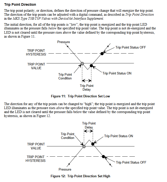
Hysteresis: default 10%, adjustable through digital commands, used to compensate for system noise and avoid "relay jitter", ideal value close to but not less than peak to peak noise.
Delay: The alarm status of the trip point needs to be continuously set for a set time (0-10000 ms, default 0) before reporting "ON". Different delay values can be set for different trip points (monitoring controller object pressure properties, trip point object valve position properties).
Direction: default "low" (when the pressure is lower than the set value, the trip point is activated, the LED lights up, and the pressure needs to be higher than the hysteresis value to release), can be changed to "high" through digital commands (when the pressure is higher than the set value, it is activated, and the pressure needs to be lower than the hysteresis value to release).
Top panel component
Connectors: Includes 5-pin miniature digital communication connector (DeviceNet communication interface), 25 pin D-type female auxiliary connector (sensor power supply, alarm relay output, RS-232 communication), 9-pin D-type male external power connector (valve power supply), and 2 15 pin D-type female analog sensor connectors (high/low sensor power supply and pressure input).
Indicator lights and switches:
Valve position indicator light: "OPEN" (red) lights up to indicate that the valve is fully open, and "CLOSE" (red) lights up to indicate that it is fully closed.
Manual valve switch: a button type switch that can manually drive the valve to the open/close position.
Trip point indicator light: It lights up green when the trip point is activated.
DeviceNet status light: including module status light (green/red dual color) and network status light (green/red dual color), the power startup sequence complies with the ODVA DeviceNet specification, the module status light is always green to indicate normal, and the red to indicate unrecoverable fault; The green constant light of the network status indicates that the communication link is normal and a connection has been established, the green flashing indicates online but no connection, and the red constant light indicates a serious link failure.
Configure switch:
Baud rate switch: 4-bit rotary switch, optional PGM (read from non-volatile memory), 125 Kb, 250 Kb, 500 Kbps.
MAC ID (Node Address) Switch: Two 10 bit rotary switches, set the node address (0-63), with ten bits on the left (MSD) and one bit on the right (LSD); When the address is greater than 63, it is equivalent to the "PGM" position.
Installation Guide
Unpacking and Inspection
Unboxing process: MKS uses professional packaging to ensure that the equipment is in good condition. After receiving it, it is necessary to check whether the valve is damaged, the connector is damaged, and other transportation damages are present. Do not discard the packaging materials until safety is confirmed.
Problem handling: If damage is found, immediately notify the carrier and MKS; If you need to return the device, you need to first obtain the ERA number (device return authorization number) from the MKS service center. The MKS calibration service center list is listed on the inside of the back cover of the manual; Only qualified personnel are allowed to install and debug, and ESD protection and operating procedures must be followed.
Standard accessories: including T3B unit, T3B with DeviceNet interface user manual, MKS T3B/T3P with DeviceNet interface supplementary manual (No. 138993-P1, installation needs to refer to this supplementary manual).
Interface cable requirements
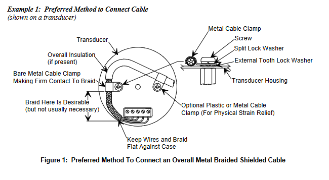
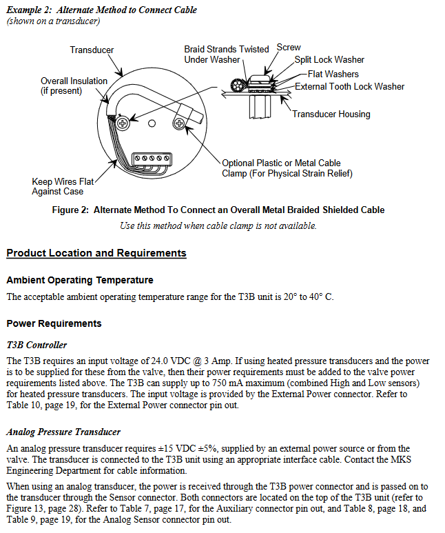
Cable specification: Full metal braided shielded cable (correctly grounded at both ends) is required to comply with CE certification; MKS provides a full range of cables, and if self-produced, they must meet the following requirements: shielding layer covering all wires (insufficient aluminum foil or spiral shielding effect may affect compliance); The metal shell of the connector is in direct contact with the entire circumference of the cable shielding layer (to avoid reduced shielding effect caused by flying wires); Good contact between the connector and the controller housing (approximately 0.01 ohms, with grounding surrounding all wires); Consider voltage level, wire I ² R heating, IR voltage drop, capacitance and inductance of fast signal cables, and internal wire shielding requirements.
Connection method: Two shielding cable connection methods are provided (priority is to use cable clamps to fix the shielding layer, and if there is no cable clamp, the shielding layer can be twisted and fixed with washers), ensuring that the shielding layer is grounded and the wire is in contact with the shell.
Installation environment and location
Environmental requirements: The working temperature range is 20 ° C-40 ° C, the working humidity is 0% -95% (non condensing), and the storage temperature range is -20 ° C-80 ° C.
Installation position: It can be installed on the vacuum exhaust pipeline (with suitable joints). To achieve optimal pressure control, the pressure sensor and T3B should be as close to the process chamber as possible to reduce the time constant; The connecting pipe between the sensor and the chamber should be less than 6 inches and have a diameter of not less than 1/4 inch. If it exceeds 6 inches, a larger diameter pipe should be used to compensate for the conductivity loss.
System configuration and electrical connections
Typical configuration: The system includes a DeviceNet network host (sending set values, receiving pressure/position/diagnostic data), a 24 VDC valve power supply, a sensor power supply (optional ± 15 VDC), a T3B unit, an analog Baratron sensor, and an alarm relay output that can be connected to external alarm devices.
Grounding requirements: If power is taken from the DeviceNet network, it must comply with the grounding requirements of the ODVA DeviceNet specification (Volume I).
Definition of connector pins:
Digital communication connector (5-pin): 1-pin (Drain), 2-pin (V+), 3-pin (V -), 4-pin (CAN_S), 5-pin (CAN_L).
Auxiliary connector (25 pins): includes receive data (RX), send data (TX), pressure output (A Out), position output (A Out), 2 sets of relays (normally open/normally closed/common terminal), valve open/closed status (digital output), interlock (digital input), analog ground, digital ground, chassis ground, etc. Pins 11-13 are related to analog signals, pins 14-19 are relays, pins 20-22 are digital status and input, and pins 24-25 are ground.
Analog sensor connector (15 pins, with the same high and low sensor pins): 2-pin (pressure input+), 5-pin (sensor power return), 6-pin (-15 V), 7-pin (+15 V), 12 pin (pressure input -), 14 pin (+24 V power output), 15 pin (chassis ground), with no other pins connected.
External power connector (9-pin): 1-2 pins (+24 V input), 3-4 pins (24 V return), 5-pin (+15 V auxiliary input, for instruments), 6-pin (15 V return), 7-pin (-15 V auxiliary input, for instruments), 8-pin (reserved), 9-pin (chassis ground).
startup process
Power on sequence: First supply power to the DeviceNet network, then supply power to T3B; When powered on, the device checks the communication link, EEPROM, and RAM internal diagnostics, and the results are indicated by the top status LED (color and flashing status).
LED startup sequence: The module status LED flashes alternately green and red for about 0.25 seconds each before turning green; The network status LED flashes alternately in green and red for about 0.25 seconds each before turning off; After initialization is completed, the module status LED remains constantly green; When there are no other network devices, the network status LED remains off; When there are other devices, the network LED flashes green during repeated MAC checks and before establishing a connection.
Preheating time: After installation and power on, the preheating time of the controller is less than 1 minute.
Operation Guide
Operation Mode
User mode: default power on mode, which is the normal operation mode.
Calibration mode: used to access specific calibration and operating parameters. The device functions are the same in both modes, but network access to certain attributes may be restricted (refer to the object attribute table in the supplementary manual for specific permissions).
Communication Configuration
Baud rate and MAC ID settings: can be set through software (DeviceNet protocol network command) or manually (top rotary switch). When powered on, if the switch is in the "PGM" position, the baud rate/address can be read from non-volatile memory, and the network can modify parameters. Changes in the switch position require a power outage and restart to take effect; If the switch is not in the "PGM" position and the switch value is directly read, the network modification request is rejected and an error code of "Attribute_Cot_Settable" is returned.
Communication specifications: Supports 125/250/500 Kbps baud rates; The network topology is linear (trunk/branch), with power and signals sharing the same cable; Supports up to 64 nodes; Explicit message communication delay<50 milliseconds (average<25 milliseconds), I/O polling message delay<4.5 milliseconds (average<1.5 milliseconds); Equipped with module status (green/red) and network status (green/red) LED indicators.
Core operational functions
Parameter setting and monitoring: Through the DeviceNet network, set values (pressure/position), valve direction (forward/reverse), pressure values and units, valve position, trip point values/hysteresis/delay/status can be set and reported, monitoring system status, reporting operating time, and setting valve soft start; Storage device identification information (manufacturer information, model serial number, factory calibration data, software and hardware version number).
Maintenance and troubleshooting
routine maintenance
Routine inspection: No special maintenance requirements, only correct installation and operation are required; Regularly check for cable wear and signs of shell damage; Regularly wipe the surface of the equipment with a damp cloth.
Equipment return: If you need to return the MKS for repair, you need to obtain the ERA number first; The returned equipment must be free of harmful, corrosive, radioactive, or toxic substances.
troubleshooting
General faults:
When the valve is closed, the conductivity does not meet the standard: it may be due to wear or damage of the baffle seal, and the factory needs to be contacted to obtain a seal replacement kit.
25 pin I/O connector interlock missing (22-24 pins): Connect pin 22 to pin 24 or verify external interlock wiring.
Valve not open/closed: Check if the 24V power supply is properly connected to the valve terminal or if the valve is faulty (need to be sent to MKS for repair); Simultaneously confirm the interlocking wiring.
Pressure control failure (report full range/low/zero): Sensor disconnected (reconnect) or pressure gauge not powered (check power supply).
Pressure control oscillation/poor effect: PID mode needs to optimize gain and phase, and the model base mode needs to relearn the pump speed curve; The control offset may be due to high grounding impedance (judged by MKS valve GUI as a debugging or grounding issue); The control difference within a specific pressure range may be due to incorrect intersection point settings (configuring and installing pressure gauges for intersection pressure).
Unable to achieve target pressure: The baffle seal is worn or damaged (replace seal).
Report negative/abnormal pressure: pressure gauge not zeroed (zeroing), no power supply (checking power supply); Pressure gauge full range setting error (configured with correct range), voltage range error.
Pump speed learning failed: The pressure gauge is not connected to the high range (retry after connecting to the high range).
Communication malfunction:
RS-232 communication failure: Check baud rate, data bits, checksum, CR-LF settings, or cable wiring issues.
DeviceNet communication failure: Check MAC address and baud rate settings, or network power supply for normal operation.
Meaning of fault indicator light:
Module status LED: evergreen (normal), flashing green (visual indication), constantly red (non recoverable fault), flashing red (minor fault, such as interlock not enabled), off (no power supply), alternating red and green (self check).
Network status LED: evergreen (communication link normal, online and connection established), flashing green (online but no connection established), constantly red (severe link failure, such as repeated MAC address or bus shutdown), flashing red (connection timeout), alternating red and green (initialization), off (not online, such as incomplete repeated MAC check or no power supply); When using a single device network, it is normal to keep it off until there is no connection.
Fault type:
Minor faults: MAC ID or baud rate switch changed during operation, safety interlock opened (only T3P gas interlock), controller error reported through abnormal status bit (refer to supplementary manual), equipment remains in operation.
Serious malfunction: During self inspection, EEPROM hardware or RAM memory issues were detected, the module status LED is constantly red, and the device has entered a serious malfunction state, unable to respond to network services. MKS needs to be contacted.
- YOKOGAWA
- Reliance
- ADVANCED
- SEW
- ProSoft
- WATLOW
- Kongsberg
- FANUC
- VSD
- DCS
- PLC
- man-machine
- Covid-19
- Energy and Gender
- Energy Access
- Renewable Integration
- Energy Subsidies
- Energy and Water
- Net zero emission
- Energy Security
- Critical Minerals
- A-B
- petroleum
- Mine scale
- Sewage treatment
- cement
- architecture
- Industrial information
- New energy
- Automobile market
- electricity
- Construction site
- HIMA
- ABB
- Rockwell
- Schneider Modicon
- Siemens
- xYCOM
- Yaskawa
- Woodward
- BOSCH Rexroth
- MOOG
- General Electric
- American NI
- Rolls-Royce
- CTI
- Honeywell
- EMERSON
- MAN
- GE
- TRICONEX
- Control Wave
- ALSTOM
- AMAT
- STUDER
- KONGSBERG
- MOTOROLA
- DANAHER MOTION
- Bentley
- Galil
- EATON
- MOLEX
- Triconex
- DEIF
- B&W
- ZYGO
- Aerotech
- DANFOSS
- KOLLMORGEN
- Beijer
- Endress+Hauser
- schneider
- Foxboro
- KB
- REXROTH
- YAMAHA
- Johnson
- Westinghouse
- WAGO
- TOSHIBA
- TEKTRONIX
- BENDER
- BMCM
- SMC
- HITACHI
- HIRSCHMANN
- XP POWER
- Baldor
- Meggitt
- SHINKAWA
- Other Brands
- UniOP
- KUKA
- IBA
- Beckhoff
- ADLINK
-
ADLINK HPCI-14S12U - Industrial Control Backplane 12PCI Backplane PCI-14S Passive Backplane
-
ADLINK PCIe-GIE74C - image acquisition card 4-CH GigE Vision PoE+ Frame Grabber
-
ADLINK PCI-8164 - control card 4-Axis Advanced Motion Controller Board
-
ADLINK PCIe-U304 - 4 Port USB3 PCIe Frame Grabbers USB Screw Hole Card
-
ADLINK PCI-9112 - Multi-Function Data Acquisition Card DAQ Card
-
ADLINK PCI-7432 - 51-12013-0A50 4-CH Isolated Numérique I/O PCI Cartes Digital I/O Card
-
ADLINK PCA-6106P3-0C1 REV.C1 - backplane 6-Slot Passive Backplane Board
-
ADLINK PCI-7224 - 24-CH Opto-Isolated Digital I/O PCI Board
-
ADLINK CPCI-7433R(G) - Digital Input Board Rear I/O CompactPCI Card
-
ADLINK EBP-13E4 - 51-46703-0A30 Industrial PC Backplane Passive Backplane
-
ADLINK PCIE-HDV62 - Image acquisition card High Definition Video Frame Grabber
-
ADLINK EBP-13E4 - 51-46703-0A30 Industrial Backplane Board Passive Backplane
-
ADLINK 90111-B1 / CPCI-6770 - PCB CPU MODULE CompactPCI Single Board Computer
-
ADLINK PCI-7248 - DATA ACQUISITION PCI CARD 48-CH Parallel Digital I/O Board
-
ADLINK PCI-7230 - 51-12003-0a50 board PCI7230 32-CH Isolated Digital I/O Card
-
ADLINK PCI2A000CB - 51-20000-0B30 Multi-Function DAQ Card Baseboard
-
ADLINK PCI-8134-005 - 4-Axis Motion Controller Card
-
ADLINK PCI-7224 - 24-CH Opto-Isolated Digital I/O PCI Card
-
ADLINK PCI-7434 - 64-CH Isolated Digital Output Card
-
ADLINK PCI-8132 - motion control card 2-Axis Servo & Stepper Controller
-
ADLINK PCI-8134 - Motion Controller PCI Card 4-Axis Controller Board
-
ADLINK PCI-8164 - Motion Control Card 51-12406-0A40 4-Axis Controller
-
ADLINK 51-12001-0C20 - Circuit Board Data Acquisition Interface Module Hardware
-
ADLINK NuPR0-840 - industrial control motherboard Full-Size PICMG CPU Board
-
ADLINK PCI-7444 - 51-12023-0A10 card 128-CH Isolated Digital Output Board
-
ADLINK PCI-1612B - data acquisition card 4-Port RS-232/422/485 Serial Communication Card
-
ADLINK PCI-6208V 009 - 8/16-CH 16-Bit Analog Output Cards PCB-I-E-482=6BX3
-
ADLINK NUPRO-935A/LV - industrial control motherboard Full-Size PICMG SBC Board
-
ADLINK PCI-9114DG - Multi-Function DAQ Card Data Acquisition PCI Card
-
ADLINK ACL-7130 - Data acquisition card Isolated Digital I/O Board
-
ADLINK ABX-6300D-4E1-BP - board ABX6300D4E1BP Video Interface Expansion Card
-
ADLINK CPCI-6940 - CPCI-6940/D1539/M16-0(EA)-000E 6U CompactPCI Processor Board
-
ADLINK NuPRO-760 - industrial control motherboard Half-Size PICMG SBC CPU Board
-
ADLINK IMB-M42H (G)-0020 - industrial control motherboard LGA1155 Micro-ATX Mainboard
-
ADLINK RTV-24 / PCI-MP4S - 51-12519-1C30 4-Channel Real Time Video Capture Board
-
ADLINK PCI-8134 - 4-Axis Servo & Stepper Motion Controller Card
-
ADLINK MXC-6101D - V.PC000.002.ST.00 Box PC Configurable Embedded Computer
-
ADLINK PCI-8134A - 51-12421-0A10 Motion Control Card 4-Axis Controller Card
-
ADLINK DIN-100S / DIN-100SA1 - Technology SCSI-II TB 100-PIN Terminal Block Board
-
ADLINK DIN-812M001 / DIN812M001 - 51-14034-0A1 51140340A1 Terminal Module Breakout Interface
-
ADLINK PCI-8164 - Servo motion control 4-Axis Advanced Controller Card
-
ADLINK PCIe-GIE64 - Acquisition card GigE Vision PoE+ Frame Grabber
-
ADLINK M-302 - Industrial control motherboard ATX PC Board Mainboard
-
ADLINK PCI-8134 - Motion Controller PCI Card 4-Axis Controller Board
-
ADLINK PCI-RTV24 - Image capture card Analog Video Frame Grabber
-
ADLINK PCI-8102 - Motion control card 2-Axis Servo & Stepper Controller Board
-
ADLINK PCI-9112 REV.B1 - Card Multi-Function Data Acquisition Card
-
ADLINK HSI-DI32-M-N / HSL-TB32-M-DIN - Discrete I/O MODULE Distributed Automation Module System
-
ADLINK PCI-7296 - IO card REV.A3 96-CH Parallel Digital I/O Card
-
ADLINK DIN-814P-A4 / 814Y - terminal board Motion Control Interface Block
-
ADLINK DIN-814P-A4 - 51-14056-0A10 PCB-I-E-2736=ZA01 Screw Terminal Board Breakout
-
ADLINK M-322 - motherboard Industrial Control Computer Mainboard
-
ADLINK NUPRO-406 REV:B1 - industrial control motherboard Full-Size PICMG CPU Board
-
ADLINK AMP-204C - card DSP-Based 4-Axis Advanced Pulse-Train Controller
-
ADLINK HPCI14S REV.B1 - industrial computer baseboard 14-Slot Passive Backplane
-
ADLINK PCI-7250 - 8-CH Relay Output & 8-CH Isolated DI PCI Card
-
ADLINK EBP-13E2 - baseplate Passive Backplane Industrial Computer Chassis Board
-
ADLINK LPCI-3488A - PCI-GPIB card 51-12801-0A30 acquisition card IEEE-488 Interface Board
-
ADLINK PCI-6216V-GL - 51-12201-0C30 16-CH 16-Bit Voltage Analog Output Card
-
ADLINK ACL-8454 - 16-CH Isolated Digital I/O & 4-CH Counter Card
-
ADLINK HPCI-9S7U - backplane Passive Backplane Compatible with NuPRO-A301 852 841 842
-
ADLINK DAQ-2010-007 - Simultaneous-Sampling Multi-Function Data Acquisition Card
-
ADLINK MP-C154 - 51-64205-0A10 Motion Control Card 4-Axis Controller Board
-
ADLINK MXE-202/mSSD16B/WiFi-BT - Matrix Rugged I/O Platform Embedded Fanless Computer
-
ADLINK CM-920-R-17 - PC/104-Plus Single Board Computer Module Intel Celeron M
-
ADLINK PCI-7250 NSMP - 8-CH Relay Output & 8-CH Isolated DI Card
-
ADLINK PCI-8164 - 4-Axis Motion Controller PCI Card W/ Cable and Breakout Box
-
ADLINK EMX-100 - Ethernet-based 4-axis Motion Controllers Distributed Motion Module
-
ADLINK PCI-8134A - Press control card 4-Axis Motion Controller Board
-
ADLINK M-845EG REV:3.2 - industrial motherboard Pentium 4 Socket 478 Micro-ATX
-
ADLINK PCI-9114A Rev A2 DG - card High-Resolution Multi-Function Data Acquisition Board
-
ADLINK IEC-915GV - REV 1.1 Industrial motherboard Socket 478 CPU Board
-
ADLINK PCI-9111DG(G) - Data Acquisition Card Multi-Function DAQ Card
-
ADLINK HPCI-15S10 REV:B2 - Industrial computer base plate Passive Backplane Board
-
ADLINK NuPR0-840 / NuPR0-840DV - industrial control motherboard Full-size PICMG CPU Board
-
ADLINK RTV-24 / PCI-MP4S - 51-12519-1C30 4-Channel Real Time Video Capture Board
-
ADLINK NUPRO-780 - industrial control motherboard Pentium III Single Board Computer
-
ADLINK PCI-7296 - 0050 card 96-CH Opto-Isolated Parallel DIO Card Set
-
ADLINK NUPRO-780 - industrial control motherboard PICMG Full-Size SBC
-
ADLINK PCI-7248 - 51-12006-0A3 002 Pci 7248 48-CH Parallel Digital I/O Card
-
ADLINK PCI-7230 - 32-CH Isolated Digital I/O Card
-
ADLINK AMP-204C - motion control card 4-Axis Advanced Controller Board
-
ADLINK PCI-1714UL - Card Ultra High-Speed 4-CH Simultaneous Sampling DAQ
-
ADLINK NuPRO-E330 - industrial computer equipment motherboard PICMG 1.3 SHB SBC
-
ADLINK AMP-204C - DSP-Based 4-Axis Advanced Pulse-Train Motion Controller Module
-
ADLINK PCI-7256 - 001 51-12206-0A2 REV.A2 LPCI-7256 16-CH Latching Relay Output Card
-
ADLINK ND6050 - NUDAM DIGITAL I/0 MODULE Distributed I/O Unit
-
ASEM BM100 - Box PC Embedded Fanless Industrial Computer
-
ADLINK PCI-7250 - PCI Acquisition Card 8-CH Relay Output & Isolated DI Board
-
ADLINK PCI-8164 - Servo motion control 4-Axis Controller Card
-
ADLINK NuPRO-A40H - Industrial Motherboard 51-41807-1A30 OSP LGA1155 H61
-
ADLINK ADMAX X300 SERVER - 51066010-0A30 motherboard Multi-Processor Mainboard
-
ADLINK CMe-GIE62+ - 51-32903-0A30 control card PC/104-Plus GigE Vision Frame Grabber
-
ADLINK NUPRO-780 - industrial control motherboard Full-Size PICMG SBC CPU Board
-
ADLINK ETX-AT-N270-18/GKTEL - 51-71111-OB10 motherboard ETX CPU Module Board
-
ADLINK DIN-812M - interface module Terminal Block Connection Board
-
ADLINK IMB-M42H - industrial control motherboard LGA1155 Micro-ATX Mainboard
-
ADLINK PXIS-2508 - 8-slot 3U PXI Instrument Chassis Power Hardware Assembly
-
ADLINK AMP-208C - Motion Control card DSP-Based 8-Axis Pulse-Train Controller
-
ADLINK PCI-9111 / PCI-9111DG - Multi-Function Data Acquisition Card DAQ Board
-
ADLINK IEEE-488 GPIB card - Bus Interface Controller Communication Board
-
ADLINK RTV-24 - 51-12519-1C30 image acquisition card Video Frame Grabber Card
-
ADLINK TB-24P/24-01 - Board 24 Way Screw Terminal Breakout Board
-
ADLINK HSL-DI16DO16-DB-NN - 51-23015-0A40 Distributed Discrete I/O Module Set
-
ADLINK PCI-7442 - switch quantity card data acquisition card 64-CH Isolated Card
-
ADLINK ACL-7130 REV. B2 - industrial control capture card Isolated Digital I/O PCI Card
-
ADLINK PCI-6S / PCI6S - Backplane 6-Slot Passive Backplane Chassis Board
-
ADLINK ACL-8113A - card Isolated Digital Input Card
-
ADLINK CPCI-6208V-003 - board cPCI CompactPCI 8-CH Analog Output Card
-
ADLINK DIN-100S-01(G) - SCSI 100-Pin Terminal Block Interface Board
-
ADLINK PCI-7433 - Isolated Digital Input Card 64-CH
-
ADLINK PCI-9812 - Synchronous sampling analog input card High-Speed DAQ Board
-
ADLINK PCI-7434 REV.B1 - PLOTECH PCB-I-E-1182=6EX2 64-CH Isolated Digital Output Card
-
ADLINK PCIe-RTV24 - 51-18016-0A20 4-CH Real-Time Video Capture Card PCIe Frame Grabber
-
ADLINK PCI-8144 / PCI-8144N - Motion control card 4-Axis Stepper Motor Controller
-
ADLINK DIN-68S-01 - terminal board 68-Pin Connector Terminal Block
-
ADLINK MP-C154 - Motion control card 4-Axis Advanced Controller Card
-
ADLINK PCI-7248 (G) - Motherboard 48-CH Parallel Digital I/O Card
-
ADLINK MXE-1301(G) - Intel Atom D2550+NM10 MXE 1300 Series 93-4130-0030 Embedded Computer
-
ADLINK PRO-841 Rev 2.0 / PRO-060907000670 - CPU 2.26GHz & RAM Industrial PC Board
-
ADLINK NuPRO-E330 - Industrial Motherboard System Host Board PICMG 1.3 SHB
-
ADLINK EBP-13E2 - Passive Backplane Industrial Chassis Baseboard
-
ADLINK PCI-8154 - 4-axis Motion Control Card Servo & Stepper Controller Board
-
ADLINK NuPrO-596 REV.B1 - industrial control motherboard Half-size PICMG CPU Board
-
ADLINK PCI-7852 / PCI-7851 - PLOTECH High-Speed Link Control Card Interface Board
-
ADLINK PCI-9112 - 51-12252-0D20 data acquisition card Multi-Function DAQ
-
ADLINK PCI-9112 - Circuit Board 51-12252-0C20 Multi-Function Data Acquisition Card
-
ADLINK NUPRO-761 REV:1.1 - industrial control motherboard PICMG Full-Size CPU Board

K-JIANG

Add: Jimei North Road, Jimei District, Xiamen, Fujian, China
Tell:+86-15305925923