
K-WANG


Tektronix 370B Programmable Curve Tracer
Key advantages: digital storage (flicker free display), precise cursor measurement (minimum resolution of 100pA), GPIB remote control, pulse mode (reducing device power consumption).
Tektronix 370B Programmable Curve Tracer
Basic Information and Quality Assurance Policy
Product positioning and applicable scenarios
Core function: Measure the static/dynamic characteristics of semiconductor devices and support the drawing of voltage current (V-I) characteristic curves for bipolar transistors, field-effect transistors (FETs), diodes, thyristors (SCR), and other devices.
Key advantages: digital storage (flicker free display), precise cursor measurement (minimum resolution of 100pA), GPIB remote control, pulse mode (reducing device power consumption).
Safety regulations and system installation
1. Core security requirements
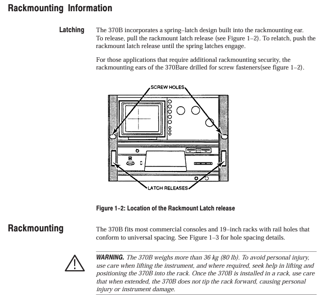
Interlocking system: The test adapter must be equipped with a protective cover. When there is no cover, the collector power supply will be automatically disabled, and the red Warning light will turn off (the light will turn on when there is a cover, indicating dangerous voltage).
Live operation taboos: Do not plug or unplug when connecting the probe/test line to the voltage source, and do not remove the protective cover for measurement.
Power safety: Before replacing the power supply, it is necessary to cut off the power and confirm that the LINE VOLTAGE SELECTOR (115V/230V) matches the local power supply. The fuse specifications cannot be mixed (4A for 115V and 2A for 230V).
2. System installation process
(1) Power configuration
Confirm the LINE VOLTAGE SELECTOR on the Rear panel: select 115V/230V for NOMINAL and HIGH-LOW for RANGE (e.g. 115V HIGH corresponds to 107-132V).
Check fuses: Open the Rear panel fuse holder. For 115V models, use a 125V/4A fast melting fuse (159-0259-00), and for 230V models, use a 250V/2A fast melting fuse (159-0260-00).
Connect the power cord: Select the corresponding plug according to the region (such as standard plug for North America or A1 option plug for Europe).
(2) GPIB settings
Rear panel GPIB Terminator and Address switch: Set the address (0-31, 31 is offline) and select the termination symbol (EOI/LF).
Cable connection: Use standard GPIB cables (such as 012-0991-00, 2m) to connect the controller to 370B, with a maximum of 15 devices in the system.
Address verification: Press and hold the FAST/SHIFT+LOCAL keys, and the CRT will display the GPIB address and termination symbol.
(3) Test adapter installation
Standard adapters: A1001 (blank), A1002 (serial), A1005 (axial lead), align with A1006-A1010 interface during installation, and do not forcefully install double width adapters to the right interface.
Core Function Operation Guide
1. Key controls on the front-end panel
(1) Collector Supply Control
Key parameters of control item function description
MAX PEAK VOLTS selects peak voltage range 16V/80V/400V/2000V (4th gear)
MAX PEAK POWER selects maximum peak power of 0.08W/0.4W/2W/10W/50W/220W (6th gear)
Polarity selects 7 output polarities and modes:+LEAKAGE (measuring emitter current, sensitivity x 1000),+DC, AC, etc
VARIABLE regulates the output ratio from 0.0% to 100.0% (with a step size of 0.1%)
LOOPING COMPENSATION Compensation parasitic capacitance maximum compensation 100pF
(2) Step Generator Control
Key parameters of control item function description
OUTPUT MODE Select output type: current (50nA-200mA/step), voltage (50mV-2V/step)
NUMBER OF STEPS: Select the number of steps from 0 to 10 (only output offset when 0 steps)
PULSE selects the pulse modes SHORT (80 μ s), LONG (300 μ s), OFF
OFFSET adjustment offset ± 10 x step amplitude (step size 1%)
Inverted output polarity is only valid in EMITTER COMMON mode
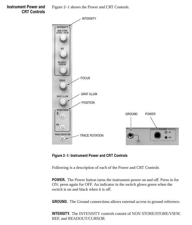
(3) Digital Storage and Display Control
Storage mode:
NON STORE: Real time simulation display (no storage);
STORE: Digital storage (1024 points/axis, resolution 10 bits);
VIEW: Call the storage curve (16 IC memories/64 floppy disks).
Collection mode:
AVG: 16 times average (noise reduction);
ENV: Vertical/Horizontal Envelope (Thermal Drift);
Norm: Conventional collection.
Cursor measurement:
DOT: Single point measurement (reading voltage/current);
F LINE: Functional line measurement (on resistance, intercept voltage);
WINDOW: Window measurement (hFE, gm).
2. Basic measurement process (taking diode forward characteristics as an example)
Install adapter: Insert the A1005 axial lead adapter into the right interface, insert the diode (anode connected to collector, cathode connected to emitter), and close the protective cover.
Configure collector power supply:
Choose 16V for MAX PEAK VOLTS, 0.4W for MAX PEAK POWER, and+DC for POLYTY.
Configure stepper generator:
Select CURRENT for OUTPUT MODE, 1mA/step for STEP AMPLITUDE, and 5 for NUMBER OF STEPS.
Start measurement:
Press MEASURE → REPEAT, adjust the VARIABLE collector power supply to 100%, and the CRT displays a positive V-I curve.
Cursor measurement:
Press CURSOR → DOT, move the cursor to the conductive area, and the CRT displays the forward voltage (such as 0.7V) and current (such as 5mA).
Typical measurement applications
1. Bipolar transistor (NPN type)
Measurement parameters: IC-VCE curve hFE、VCE (sat)、ICE0;
Key settings:
Configuration: CONFIG → BASE STEP GEN (emitter common ground);
Collector power supply: MAX PEAK VOLTS=80V, POLYITY=+DC;
Stepper generator: CURRENT mode, 50 μ A/step, 10 steps;
Measurement method: Use the WINDOW cursor to select adjacent curves, and the CRT will automatically display hFE (such as 250).
2. Field effect transistor (N-channel enhanced type)
Measurement parameters: ID-VDS curve gm、IDSS;
Key settings:
Configuration: CONFIG → BASE STEP GEN;
Collector power supply: MAX PEAK VOLTS=40V, POLYITY=+DC;
Step generator: VOLTAGE mode, 500mV/step, 8 steps;
Measurement method: Fit the ID-VGS curve with the f LINE cursor, and the slope is gm (e.g. 40mS).
3. Zener diode
Measurement parameters: reverse breakdown voltage (Vz), leakage current (IR);
Key settings:
Collector power supply: MAX PEAK VOLTS=400V, POLYITY=- DC;
Vertical sensitivity: 10 μ A/div (for IR measurement), 1mA/div (for breakdown current measurement);
Measurement method: The DOT cursor is positioned at the breakdown inflection point, and the CRT displays Vz (such as 12V).
GPIB remote control
1. Command format and examples
Basic format: keywords (abbreviations must include uppercase parts)+parameters, multiple commands separated by semicolons;
Example 1: Set collector power polarity: CSPOL PDC (PDC=+DC);
Example 2: Read the status of the stepper generator: STPgen? Return STPGEN NUMBER: 5, PULSE: OFF, OFFSET: 0.00, INVERT: OFF, MULT: OFF, CURRENT: 1.0E-3.
2. Data transmission process (waveform data)
Sending preamble query: WFMpre? Return waveform parameters (such as sampling point 1024, X-axis unit V);
Sending curve data query: CURVE? Return binary data (2-byte count+4096 byte coordinates+1-byte checksum);
Receiving data: The controller parses the data and converts it into a V-I curve (X=voltage, Y=current).
3. Common status codes
Suggestions for handling the meaning of status bytes (decimal)
65 power on completed normally, measurement can begin
97 command errors (such as syntax errors) check the command format, refer to Table 4-6
98 Execution error (such as parameter out of range) Confirm that the parameter is within the allowable range (such as AUX voltage ± 40V)
192 Device Specific Events (such as Full Floppy Disk) Replace Floppy Disk or Delete Old Data
Maintenance and troubleshooting
1. Self inspection process
Power on self-test: automatically detects ROM/RAM/buttons after powering on, displays SELETEST PASS as normal, flashes 0/1 indicates ROM error;
Detailed self-test: Press and hold FAST/SHIFT during startup, sequentially check the LED, display quality, and buttons, and press FAST/SHIFT to exit.
2. Common faults and solutions
Possible causes and solutions for the fault phenomenon
Collector power supply disabled (COL. Disabled) protection cover not closed, over temperature closed protection cover/waiting for cooling (COL. RECORDED prompt for recovery)
FD Read Error: The floppy disk is damaged and not formatted. Replace the floppy disk or perform formatting (FAST/SHIFT+SAVE → SAVE)
Insufficient cursor display intensity, mode error adjustment READOUT/CURSOR intensity, confirm in STORE/VIEW mode
3. Cleaning and maintenance
External cleaning: Use neutral cleaner and dust-free cloth to wipe the panel, and use ethanol to wipe the CRT;
Internal cleaning: Only qualified personnel are allowed to operate, use low-pressure compressed air (9psi) to blow off dust, and prohibit the use of high-pressure air (to prevent ESD);
Calibration cycle: It is recommended to calibrate once a year, referring to the performance verification process in Appendix A.
- YOKOGAWA
- Reliance
- ADVANCED
- SEW
- ProSoft
- WATLOW
- Kongsberg
- FANUC
- VSD
- DCS
- PLC
- man-machine
- Covid-19
- Energy and Gender
- Energy Access
- Renewable Integration
- Energy Subsidies
- Energy and Water
- Net zero emission
- Energy Security
- Critical Minerals
- A-B
- petroleum
- Mine scale
- Sewage treatment
- cement
- architecture
- Industrial information
- New energy
- Automobile market
- electricity
- Construction site
- HIMA
- ABB
- Rockwell
- Schneider Modicon
- Siemens
- xYCOM
- Yaskawa
- Woodward
- BOSCH Rexroth
- MOOG
- General Electric
- American NI
- Rolls-Royce
- CTI
- Honeywell
- EMERSON
- MAN
- GE
- TRICONEX
- Control Wave
- ALSTOM
- AMAT
- STUDER
- KONGSBERG
- MOTOROLA
- DANAHER MOTION
- Bentley
- Galil
- EATON
- MOLEX
- Triconex
- DEIF
- B&W
- ZYGO
- Aerotech
- DANFOSS
- KOLLMORGEN
- Beijer
- Endress+Hauser
- schneider
- Foxboro
- KB
- REXROTH
- YAMAHA
- Johnson
- Westinghouse
- WAGO
- TOSHIBA
- TEKTRONIX
- BENDER
- BMCM
- SMC
- HITACHI
- HIRSCHMANN
- XP POWER
- Baldor
- Meggitt
- SHINKAWA
- Other Brands
- UniOP
- KUKA
- IBA
- Beckhoff
-
ADLINK CPCI-6860A - 51-31310-OB10 industrial motherboard CompactPCI SBC
-
ADLINK AmITX-SL-G-H110 - 51-7A104-0A30 Mini-ITX Industrial Motherboard
-
ADLINK PXI-2005-003 - CPCI Industrial PC Data Acquisition Card Multi-Function DAQ
-
ADLINK DININ-814M - 51-14032-0A3D SCSI-100P cable connection Interface Terminal Board
-
ADLINK CPCI-3920NA/C2D15/M1G - 3U CompactPCI Intel Core 2 Duo Single Board Computer
-
ADLINK PCIE-8560 - 51-18014-0A20 Communication Card High Speed DAQ
-
ADLINK PCI-C154+ - Motion Control Card 4-axis Motion Controller Board
-
ADLINK PCI-RTV24 - image capture card Analog Video Frame Grabber
-
ADLINK NuPRO-842LV/P - 51-41360-0B30 Industrial Motherboard CPU Board
-
ADLINK cBP-3208/3208R - CPCI Board 3U 8-Slot CompactPCI Backplane
-
ADLINK PCI-8164 - 4-Axis Motion Controller PCI Card 51-12406-0A40
-
ADLINK PCIe-GIE64+ - 4-CH GigE Vision PoE+ Frame Grabber Video Capture Card
-
ADLINK CPCI-6860 / 6860A - CompactPCI Dual Xeon Single Board Computer
-
ADLINK IEC-915GV - REV 1.1 Industrial motherboard CPU Board
-
ADLINK ND-6520 - Technology RS-232 to RS-422RS-485 Converter NuDAM Module
-
ADLINK RTV-24 / PCI-MP4S - 51-12519-1C30 4-Channel Real Time Video Capture Board
-
ADLINK cPCI-6910 / cPCI-6910AM/M1G - cPCI-6910AM/DXL16/M1G/S80G(G)-3120 BOARD CompactPCI SBC
-
ADLINK NUPRO-A40H - Linghua 51-41807-1A30 Industrial Control Computer Motherboard
-
ADLINK USB-3488A - USB to GPIB INTERFACE USB-3488A(G) Controller Module
-
ADLINK PCI-8134A - motion control card 4-Axis Controller Card
-
ADLINK PCI-7432 - Board 32-Channel input / 32-output Isolated Digital I/O PCI Card
-
ADLINK PCI-8134A - 51-12421-0A10 motion controller card tested
-
ADLINK LPCIe-7230 - 32 CH Isolated Input/output Card 2 Interrupts Low Profile PCIe
-
ADLINK NuPRO-E340 - industrial computer motherboard 51-47807-0A30 PICMG 1.3 SHB
-
ADLINK PCI-7434 - High-speed Digital Acquisition Card 64-CH Isolated DO Card
-
ADLINK NuPRO-E330 - 51-41805-0A20 Indsutrial Board SHB Single Board Computer
-
ADLINK PCI-7248 - OPTO-22 48 CHANNEL DIO DIGITAL TTL/DTL I/O 51-12006-0A40 GP
-
ADLINK PCI-8134 - Motion control card 4-Axis Controller Card
-
ADLINK AMP-208C - Movimiento Control Tarjeta 51-12420-1A20 W/Expansión & Breakout
-
ADLINK PCI-8164 - 51-12406-0A40 PCB Board 4-Axis Motion Controller Card
-
ADLINK DIN-68Y-SGII / DIN-68M-J3A - Terminal Board Connector Interface Block
-
ADLINK PCIe-7432 - Technology 51-18402-0A10 PCIe Card With High Input Range
-
ADLINK PCI-8144 / PCI-8144N - Motion control card 4-Axis Stepper Controller Card
-
ADLINK HSL-HUB3/REPEATER - HIGH SPEED LINK EXTENSION MODULES Distributed Hub Module
-
ADLINK ND-6017 - Data Logging + Acquisition 8CH A/D input Mod NuDAM Module
-
ADLINK LPCIe-7250 - data acquisition card Low Profile 8-CH Relay Output Card
-
ADLINK PCI-7432 - I/O card 64-CH Isolated Digital Input Output PCI Card
-
ADLINK IMB-M43H - industrial control computer motherboard Q87 Chip Micro-ATX
-
ADLINK MP-C154 - Motion control Card 4-Axis Motion Controller Board
-
ADLINK PCI-RTV24 - image capture card Video Frame Grabber Card
-
ADLINK PCI-7250 - 8-CH Relay Output & 8-CH Isolated DI Card
-
ADLINK PCI-6308V - 8-CH 12-Bit Isolated Analog Output PCI Card PCB-I-E-1148=6EX2
-
ADLINK PCI-7248 - capture card 48-CH Opto-22 Compatible DIO Card
-
ADLINK HSL-AI16A02-M-VV - Analog Input Output Distributed Module
-
ADLINK NuPRO-A301 - Rev:1.4 NUPRO-A301 PICMG Full-Size Single Board Computer
-
ADLINK PCI-6208V-GL - 8-CH Voltage Analog Output PCI Card
-
ADLINK PCI-8134A - 51-12421-0A10 4-Axis Motion Controller Card
-
ADLINK MNET-S23 - TECHNOLOGY MNET S23 - SERVO DRIVER CONTROL MODULE
-
ADLINK M-342 - ATX I3 I5 I7 Q67 Industrial Motherboard
-
ADLINK NUPRO-780 - Industrial Motherboard CPU Board PICMG SBC
-
ADLINK MP-C154 / MP-C152 - 4-Axis Motion Control Card Pulse-Train Controller
-
ADLINK NuPRO-935A/LV10B0 - Motherboard 51-41802-0A10 GP w/RAM Industrial Control Board
-
ADLINK MP-C154 - Motion control card 4-Axis Motion Controller Mainboard
-
ADLINK PCI-7250 - PCI Acquisition Card 8-CH Relay Output Isolated DI Card
-
ADLINK ACL-7124 - Technology Inc.24 DIO Card Digital Input Output Card
-
ADLINK PCI-8554 A2 - Timer/Counter Data Acquisition Card
-
ADLINK DIN-825-GP4 - Terminal Block Interface Board Breakout Module
-
ADLINK NuPR0-761 - REV:1.1 Industrial motherboard Full-Size PICMG SBC
-
ADLINK MXE-1401/M8G (G) - Matrix Fanless Embedded Computer Industrial PC
-
ADLINK HSL-DI16DO16-UD-NN - Digital 16 Channel I/O Mod Distributed I/O Module
-
ADLINK ND6520 - NUDAM INTELLIGENT DA&C MODULE RS232-RS-422/RS485 CONVERTOR
-
ADLINK NUPRO-761 - REV:1.1 Industrial Motherboard CPU Board
-
ADLINK AMP-208C - Motion Control Card 51-12420-1A20 DSP-based 8-axis
-
ADLINK NuPRO-A301REV 1.4 - with packaging industrial computer motherboard PICMG SBC
-
ADLINK PCM-9112+ - 51-12300-0A2 industrial motherboard Multi-Function DAQ PC/104 Module
-
ADLINK PCM-7250+ - 8-CH Relay Outputs & 8-CH Isolated DI Module PC/104
-
ADLINK PCI-RTV24 - Image capture card Analog Video Frame Grabber
-
ADLINK PCI-8134 - Motion Controller PCI Card 4-Axis Controller Board
-
ADLINK PCI-7432 - Isolated Digital I/O PCI Card
-
ADLINK PCI-8554 A2 - acquisition card Timer/Counter Card
-
ADLINK PCI-8132 - Rev.A2 2-Axis Servo & Stepper Motion Controller Card
-
ADLINK PCI-8132 - Data Acquisition card 2-Axis Motion Controller Card
-
ADLINK EBP-13E4 - 51-46703-0A30 Industrial Backplane Board Passive Backplane
-
ADLINK PCI-800L - Electronic Card Interface Controller Card
-
ADLINK PCIe-GIE72 - 51-18531-0A10 PCB Board GigE Vision Frame Grabber
-
ADLINK DAQ-2010(G)-OOBO - Simultaneous-Sampling Multi-Function DAQ Card
-
ADLINK PCI-9112 - REV.B1 Multifunction DAQ Card Data Acquisition Card
-
ADLINK PCI-7230 - 51-12003-DA60 32-CH Isolated Digital I/O Card
-
ADLINK PCI-7432 - Data Acquisition Card Isolated Digital I/O PCI Card
-
ADLINK ETX-AT-N270-18/LXE - 51-71111-0A20 ETX CPU Module Motherboard
-
ADLINK HSL-DI32-UD-N - DIGITAL INPUT 32 POINTS MODULE Distributed I/O
-
ADLINK AMP-204C - Motion Control card DSP-Based 4-Axis Advanced Controller
-
ADLINK MNET-4XMOG-0050 - Four-axis Motion Controller Distributed Motion Module
-
ADLINK AMP-204C - Motion control card DSP-Based 4-Axis Pulse-Train Controller
-
ADLINK PCI-7442 - Switch card 64-Channel Datalogging & Acquisition Card
-
ADLINK M-302 - Industrial control motherboard ATX PC Board
-
ADLINK NUPRO-852 / NUPRO-852LV - Industrial motherboard Single Board Computer
-
ADLINK PCI-8134 - REV.B1. 4-Axis Motion Controller Card
-
ADLINK PCI-GIE62 + - 51-18502-0A20 2-CH GigE Vision Frame Grabber PoE Card
-
ADLINK PCI-MPG24 - 51-12523-0B20 MPEG4 Card Video Compression Hardware
-
ADLINK HSL-TB32-M-DIN - 32-CH I/O TERMINAL W/ HSL-AI16AO2-M-VV MODULE
-
ADLINK PCI-M114-GL - PCB Ver 2.1 Motion Controller Axis Card
-
ADLINK IMB-M40H - SYM76996H61 motherboard Industrial Computer Mainboard
-
ADLINK NUPRO-A40H - 51-41807-1A20 industrial control motherboard H61 Chip
-
ADLINK PCI-M114-GL - Axis Card Data Acquisition Card PCB VER2.2 Motion Controller
-
ADLINK PCI-8134 - Motion Controller PCI Card 4-Axis Controller Board
-
ADLINK PCI-8102 - Motion control card 2-Axis Servo & Stepper Controller
-
ADLINK NuPRO-841REV:3.0 - motherboard Industrial Control PC Board
-
ADLINK HSL-TB32-U-DIN REV A1 - Breakout Terminal Board Field I/O Module
-
ADLINK AMP-204C - Motion Control card DSP-Based 4-Axis Pulse-Train Controller
-
ADLINK NUPRO-A40H - 51-41807-1A20 industrial control motherboard H61 PC Board
-
ADLINK PCI-6308A / PCI-6308V - 51-12202-0A50 Isolated Analog Output Card
-
ADLINK AMP-204C - DSP-Based 4-Axis Advanced Pulse-Train Motion Controller
-
ADLINK PCI-7434 - Technology 64-Channel Isolated Digital I/O PCI Cards
-
ADLINK CPCI-6840 / CPCI-6840V / PM16/M1G-12G0 - CompactPCI Single Board Computer CPU Module
-
ADLINK PCIE-GIE74 - Motherboard Video Capture Card 51-18531-0A10 Frame Grabber
-
ADLINK NuPRO-E330 - industrial computer equipment motherboard Control Mainboard
-
ADLINK AMP-208C / 51-12420-1A20 - Motion Control Card W/ Expansion & Breakout Board
-
ADLINK HPCI-14S12U - industrial computer baseboard Passive Backplane 14 Slots
-
ADLINK PCI-8164 - 4-Axis Motion Controller PCI Card W/ 1x Cable, 1x Breakout Box
-
ADLINK PCIe-RTV24 - 51-18016-0A20 Image Acquisition Video Capture Card
-
ADLINK M-342 - 5 PCI ATX Motherboard Industrial PC Mainboard
-
ADLINK PCI-FIW64 - 4/2 Channel IEEE1394B Image Capture Card FireWire Frame Grabber
-
ADLINK PCI-7432 - digital IO card 64-CH Isolated Digital Input Output Card
-
ADLINK 51-12001-0C20 - Circuit Board PCI-7200 Data Acquisition Controller Card
-
ADLINK PXI-3920 - PXI 3U cPCI Industrial Controller Embedded System CPU Board
-
ADLINK NuPRO-841REV:2.0 - motherboard Industrial Control PC Board
-
ADLINK NuPro-E330 - 51-41805-0A20 PCB Industrial Control Computer Motherboard
-
ADLINK PCI-RTV24 - Image capture card Analog Video Frame Grabber
-
ADLINK PCI-7442 - Switch card 64-Channel Datalogging & Acquisition Card
-
ADLINK HPX-13S4 - device baseboard Passive Backplane Riser Card
-
ADLINK PCI-9112 REV A.1 - Multi Function DA&C Board Data Acquisition Card
-
ADLINK PCI-7248 - 51-12006-0A40 Card Control 48-CH Digital I/O Module
-
ADLINK CPCI-6860 / 6860A - motherboard CompactPCI Dual Xeon Single Board Computer
-
ADLINK DPAC-3020-11(G) - Embedded PC Automation Controller Machine Control Board
-
ADLINK NuPRO-841 REV:1.0 - industrial control motherboard CPU Board
-
ADLINK MNET-4XMOG-0050 - Four-axis Motion Controller MNET Motion Control Card
-
ADLINK ETX-AT-N270-18/LXE - 51-71111-0A20 ETX CPU Module Motherboard

K-JIANG

Add: Jimei North Road, Jimei District, Xiamen, Fujian, China
Tell:+86-15305925923