
K-WANG


TEKTRONIX TCPA300/400 current probe amplifier
Probe: TCP312(30A/100MHz)、TCP305(50A/50MHz)、TCP303(150A/15MHz)、TCP404XL(750A/2MHz, Discontinuous).
TEKTRONIX TCPA300/400 current probe amplifier
Product positioning
Product portfolio:
Amplifier: TCPA300 (supports TCP312/305/303 probes), TCPA400 (only supports TCP404XL probes);
Probe: TCP312(30A/100MHz)、TCP305(50A/50MHz)、TCP303(150A/15MHz)、TCP404XL(750A/2MHz, Discontinuous).
Safe operation and system configuration
1. Core security standards
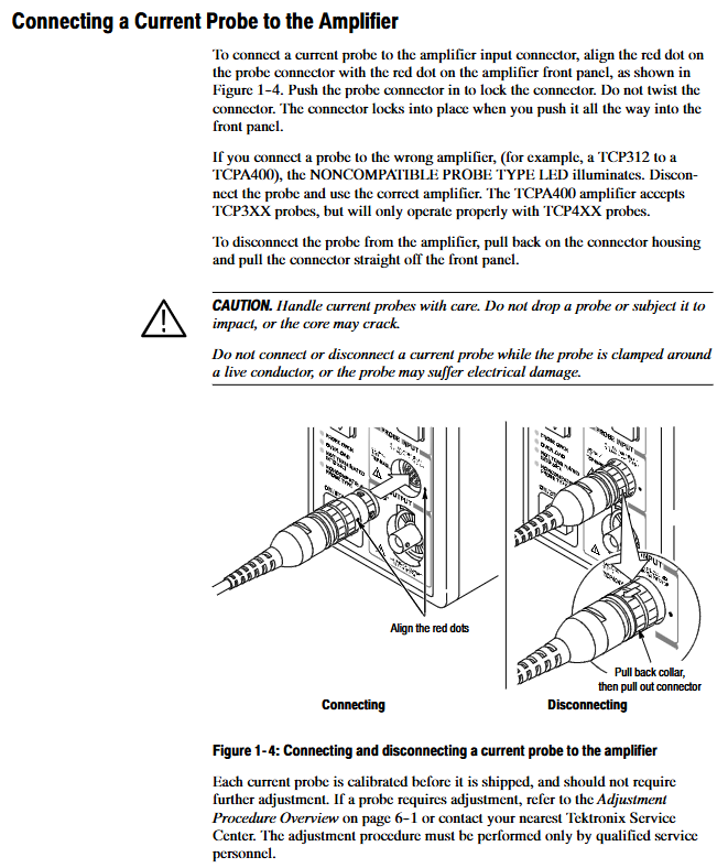
Prohibited live operation: Before connecting/disconnecting the probe/test line, the voltage source must be cut off to avoid insulation breakdown inside the probe;
Terminal matching requirements: The amplifier output needs to be connected to a 50 Ω load (oscilloscope or 50 Ω through terminal), otherwise the NOT TERMINATED IN 50 Ω LED will light up, affecting measurement accuracy;
Wire usage restrictions:
TCP312/305: Only insulated wires can be tested, and contact with exposed conductors is prohibited;
TCP303/404XL: can measure exposed conductors, but the probe needs to be removed and installed after power failure;
Environmental restrictions: Prohibit humid/explosive environments, working humidity of 5% -95% (≤ 30 ℃), 5% -85% (>30 ℃ -+50 ℃), non condensing.
2. System configuration and connection
(1) System composition
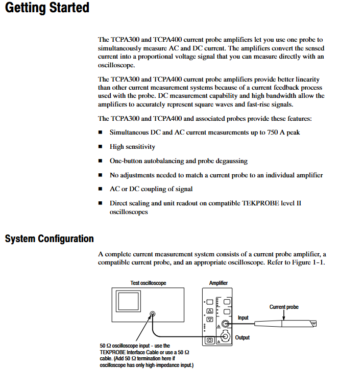
A complete current measurement system requires three parts:
TCPA300/400 amplifier: converts probe induced current into proportional voltage;
TCP300/400 series probe: clamp type induction current (effective after sliding cover locking);
Oscilloscope: requires a 50 Ω input impedance (if not available, add a 50 Ω straight through terminal), and the recommended bandwidth is 5 times the probe (e.g. TCP312 requires ≥ 500MHz oscilloscope).
(2) Connection steps
Amplifier → Oscilloscope:
TEKPROBE compatible oscilloscope: use TEKPROBE interface cable;
Non compatible oscilloscope: use 50 Ω BNC wire, set the oscilloscope input to 50 Ω;
Probe → Amplifier: Align the red marked points of the probe and amplifier, and lock them in place (do not twist);
Preheating: All equipment should be powered on and preheated for 20 minutes to ensure thermal stability.
Core Function Operation Guide
1. Key operations of the probe
(1) Demagnetization and automatic balancing (mandatory steps)
Function: Eliminate residual magnetism in the probe core, offset DC offset in the amplifier, and avoid measurement errors;
Trigger conditions: The probe slide is locked and disconnected from the live conductor;
Operation steps:
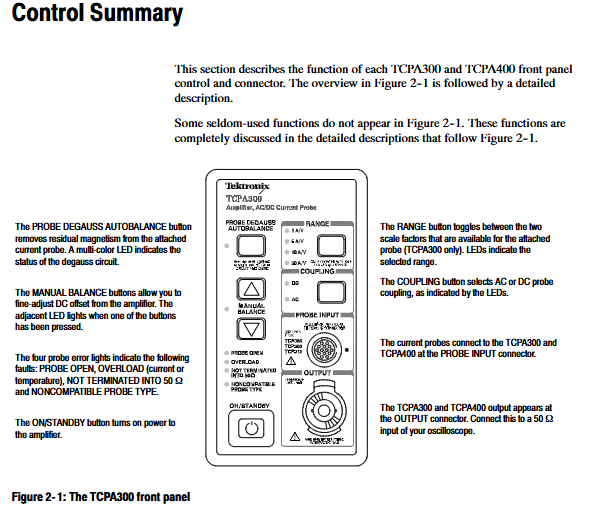
Press the PROBE DEGAUSS AUTOBALANCE button on the amplifier;
Wait for 5 seconds, the LED will flash from orange to green (successful), red (failed, terminal/probe connection needs to be checked);
Trigger scenarios: after startup, replacement of probe, overload, exposure to strong magnetic field.
(2) Sliding operation (different probe differences)
Probe model, sliding cover, opening method, locking method, precautions
TCP312/305 pulls the sliding cover backwards and pushes it forward until the buckle is fixed, only clamping the insulated wire
TCP303/404XL press lock+press handle release handle+press lock can clamp exposed wires (power-off operation)
2. Amplifier core control
(1) Key buttons and indicators
Control/indication function description exception handling
The COUPLING key switches between AC/DC coupling (AC only measures AC, DC measures AC/DC), and flashing indicates the display of Error Code
The RANGE key (TCPA300) switches the range (1/5/10/50A/V), and the LED indicates the current range. If the LED is not on, it means that the probe is not connected
PROBE OPEN LED probe slide not locked and turns off after locking the slide
OVERLOAD LED red: current beyond continuous range; Orange: Overtemperature; Flashing: Both exceed power-off cooling+demagnetization
NOT TERMINATED LED amplifier output not connected to 50 Ω load. Check oscilloscope impedance or add terminal
(2) Manual balancing (under DC coupling)
Function: Fine tune DC offset to improve measurement accuracy;
Operation: Press the MANUAL BALANCE key (left and right keys to adjust the offset direction), the LED lights up to indicate entering manual mode;
Limitation: Only DC coupling is effective, disabled under AC coupling.
3. Measurement process (taking DC current as an example)
Preheat the system for 20 minutes, set the amplifier to DC coupling, and set the oscilloscope input to 50 Ω;
Probe slide lock (no conductor), perform demagnetization/automatic balancing;
Adjust the grounding reference of the oscilloscope to the target scale;
Open the probe slide cover, clamp the tested conductor (probe arrow pointing in the normal current direction: positive → negative), and lock the slide cover;
Adjust the oscilloscope time base, trigger and gain, and read the current value (current=oscilloscope voltage value/amplifier range, for example, 2V corresponds to 10A at 5A/V range).
Performance validation and calibration
1. Preconditions for Performance Verification
Environmental conditions: temperature 23 ℃± 5 ℃, humidity meets requirements, no strong magnetic field;
Equipment requirements: current source (0.1% accuracy), DMM (5.5bit resolution), high-frequency current loop, etc. (see Table 5-3/5-11/5-17 for details);
Data recording: Corresponding test record forms (such as TCPA300 Table 5-16, TCP305 Table 5-29) need to be filled out.
2. Core testing items (amplifier+probe)
(1) DC gain accuracy test (taking TCP305 as an example)
Equipment connection: current source → 5-turn current loop → probe → amplifier → DMM (50 Ω terminal);
Test steps:
After demagnetization, the probe clamps the current loop and the current source outputs+1.00A;
Record the DMM voltage value M1, and then output -1.00A to record M2;
Calculation error:% Error=[(M1-M2) -2 × VE]/(2 × VE) × 100% (VE is the expected voltage, such as 1A corresponding to 1V in the 5A/V range);
Qualified range: ≤± 3% (guaranteed value), ≤± 1% (typical value).
(2) Bandwidth test (using TCP312 as an example)
Equipment connection: level sine wave generator → high-frequency current loop → probe → amplifier → oscilloscope;
Test steps:
The generator outputs a 3MHz, 3Vpp signal and records the oscilloscope peak to peak value M1;
Adjust the generator frequency to 100MHz (TCP312 bandwidth) and record M2;
Verification: (M2/M1) × 1.18 ≥ 0.707 (1.18 is the impedance correction factor);
Qualified range: -3dB bandwidth ≥ 100MHz.
(3) Rise time test (taking TCP404XL as an example)
Equipment connection: High voltage pulse generator → Built in current loop → Probe → Amplifier → Oscilloscope;
Test steps:
The generator outputs 5A, 250 μ s pulses, and the oscilloscope is set to 80ns/div;
Measure the rise time of pulses ranging from 10% to 90%;
Qualified range: ≤ 175ns (derived from a bandwidth of 2MHz: 0.35/2MHz=175ns).
3. Calibration adjustment (only operated by qualified personnel)
(1) Amplifier adjustment (TCPA300)
Prerequisite: The casing needs to be disassembled and a calibration adapter (174-4765-00) needs to be used;
Step: The current source outputs 0.100A, adjust the corresponding range potentiometer (such as adjusting the 25 Ω potentiometer for 5A/V) to make the DMM voltage meet the expected value (such as 0.1A corresponding to 0.25V at 5A/V range).
(2) Probe adjustment (TCP305/312)
DC gain adjustment: Open the probe housing and adjust the DC gain potentiometer to make the DMM voltage error ≤ ± 3% (refer to Table 6-7);
Attention: Record the original position before adjustment to avoid exceeding the specifications.
Troubleshooting and Maintenance
1. Common faults and solutions
Possible causes and solutions for the fault phenomenon
Demagnetization failed (LED red), 50 Ω load not connected, probe not locked, check terminal+lock slide cover
OVERLOAD LED constantly on, current exceeding range, probe overheating, current reduction+power-off cooling+demagnetization
The measurement value is not accurate without demagnetization, the range is selected incorrectly, the terminal is not connected to demagnetization+check the range+check the 50 Ω load
The probe without output signal is not connected, and the coupling is set to AC (measuring DC). Connect the probe and switch the DC coupling
2. Interpretation of Error Code
Display mode: AC/DC coupled LED flashes alternately, and 4 fault LEDs (PROBE OPEN is MSB, NONCOMPATIBLE is LSB) display a 4-digit binary code;
Common code:
Code 1: No Hall element detected in the probe → Reconnect or replace the probe;
Code 2: DC offset calibration failed → restart amplifier+demagnetization;
Code 15: Internal software error - If restarting is ineffective, contact after-sales service.
3. Daily maintenance
Cleaning: Wipe the outer shell with 75% isopropanol, and do not use solvents such as benzene/acetone;
Storage: Non working temperature -40 ℃ -+75 ℃, avoid moisture/dust;
Calibration cycle: It is recommended to calibrate once a year, with a reference frequency error (± 10ppm) valid for one year.
Accessories and Replacement Parts
1. Standard accessories (included with the product)
Category, accessory name, purpose
Amplifier accessory 50 Ω straight through terminal (011-0049-02) matching output impedance
Connect the TEKPROBE interface cable (012-1605-00) to the TEKPROBE oscilloscope
BNC line (012-0117-00) connected to non TEKPROBE oscilloscope
Probe accessories Probe cover (016-1923-00) protects the probe
Grounding lead (196-3120-01) probe grounding
2. Key replacement parts (partial)
Component type, model, and part number
TCPA300 motherboard circuit motherboard 671-5434-00
TCP305 coil current transformer component 120-184-00
TCP404XL cable probe cable assembly 174-4816-00
Amplifier fan axial fan (12VDC) 119-6721-00
- YOKOGAWA
- Reliance
- ADVANCED
- SEW
- ProSoft
- WATLOW
- Kongsberg
- FANUC
- VSD
- DCS
- PLC
- man-machine
- Covid-19
- Energy and Gender
- Energy Access
- Renewable Integration
- Energy Subsidies
- Energy and Water
- Net zero emission
- Energy Security
- Critical Minerals
- A-B
- petroleum
- Mine scale
- Sewage treatment
- cement
- architecture
- Industrial information
- New energy
- Automobile market
- electricity
- Construction site
- HIMA
- ABB
- Rockwell
- Schneider Modicon
- Siemens
- xYCOM
- Yaskawa
- Woodward
- BOSCH Rexroth
- MOOG
- General Electric
- American NI
- Rolls-Royce
- CTI
- Honeywell
- EMERSON
- MAN
- GE
- TRICONEX
- Control Wave
- ALSTOM
- AMAT
- STUDER
- KONGSBERG
- MOTOROLA
- DANAHER MOTION
- Bentley
- Galil
- EATON
- MOLEX
- Triconex
- DEIF
- B&W
- ZYGO
- Aerotech
- DANFOSS
- KOLLMORGEN
- Beijer
- Endress+Hauser
- schneider
- Foxboro
- KB
- REXROTH
- YAMAHA
- Johnson
- Westinghouse
- WAGO
- TOSHIBA
- TEKTRONIX
- BENDER
- BMCM
- SMC
- HITACHI
- HIRSCHMANN
- XP POWER
- Baldor
- Meggitt
- SHINKAWA
- Other Brands
- UniOP
- KUKA
- IBA
- Beckhoff
-
ADLINK CPCI-6860A - 51-31310-OB10 industrial motherboard CompactPCI SBC
-
ADLINK AmITX-SL-G-H110 - 51-7A104-0A30 Mini-ITX Industrial Motherboard
-
ADLINK PXI-2005-003 - CPCI Industrial PC Data Acquisition Card Multi-Function DAQ
-
ADLINK DININ-814M - 51-14032-0A3D SCSI-100P cable connection Interface Terminal Board
-
ADLINK CPCI-3920NA/C2D15/M1G - 3U CompactPCI Intel Core 2 Duo Single Board Computer
-
ADLINK PCIE-8560 - 51-18014-0A20 Communication Card High Speed DAQ
-
ADLINK PCI-C154+ - Motion Control Card 4-axis Motion Controller Board
-
ADLINK PCI-RTV24 - image capture card Analog Video Frame Grabber
-
ADLINK NuPRO-842LV/P - 51-41360-0B30 Industrial Motherboard CPU Board
-
ADLINK cBP-3208/3208R - CPCI Board 3U 8-Slot CompactPCI Backplane
-
ADLINK PCI-8164 - 4-Axis Motion Controller PCI Card 51-12406-0A40
-
ADLINK PCIe-GIE64+ - 4-CH GigE Vision PoE+ Frame Grabber Video Capture Card
-
ADLINK CPCI-6860 / 6860A - CompactPCI Dual Xeon Single Board Computer
-
ADLINK IEC-915GV - REV 1.1 Industrial motherboard CPU Board
-
ADLINK ND-6520 - Technology RS-232 to RS-422RS-485 Converter NuDAM Module
-
ADLINK RTV-24 / PCI-MP4S - 51-12519-1C30 4-Channel Real Time Video Capture Board
-
ADLINK cPCI-6910 / cPCI-6910AM/M1G - cPCI-6910AM/DXL16/M1G/S80G(G)-3120 BOARD CompactPCI SBC
-
ADLINK NUPRO-A40H - Linghua 51-41807-1A30 Industrial Control Computer Motherboard
-
ADLINK USB-3488A - USB to GPIB INTERFACE USB-3488A(G) Controller Module
-
ADLINK PCI-8134A - motion control card 4-Axis Controller Card
-
ADLINK PCI-7432 - Board 32-Channel input / 32-output Isolated Digital I/O PCI Card
-
ADLINK PCI-8134A - 51-12421-0A10 motion controller card tested
-
ADLINK LPCIe-7230 - 32 CH Isolated Input/output Card 2 Interrupts Low Profile PCIe
-
ADLINK NuPRO-E340 - industrial computer motherboard 51-47807-0A30 PICMG 1.3 SHB
-
ADLINK PCI-7434 - High-speed Digital Acquisition Card 64-CH Isolated DO Card
-
ADLINK NuPRO-E330 - 51-41805-0A20 Indsutrial Board SHB Single Board Computer
-
ADLINK PCI-7248 - OPTO-22 48 CHANNEL DIO DIGITAL TTL/DTL I/O 51-12006-0A40 GP
-
ADLINK PCI-8134 - Motion control card 4-Axis Controller Card
-
ADLINK AMP-208C - Movimiento Control Tarjeta 51-12420-1A20 W/Expansión & Breakout
-
ADLINK PCI-8164 - 51-12406-0A40 PCB Board 4-Axis Motion Controller Card
-
ADLINK DIN-68Y-SGII / DIN-68M-J3A - Terminal Board Connector Interface Block
-
ADLINK PCIe-7432 - Technology 51-18402-0A10 PCIe Card With High Input Range
-
ADLINK PCI-8144 / PCI-8144N - Motion control card 4-Axis Stepper Controller Card
-
ADLINK HSL-HUB3/REPEATER - HIGH SPEED LINK EXTENSION MODULES Distributed Hub Module
-
ADLINK ND-6017 - Data Logging + Acquisition 8CH A/D input Mod NuDAM Module
-
ADLINK LPCIe-7250 - data acquisition card Low Profile 8-CH Relay Output Card
-
ADLINK PCI-7432 - I/O card 64-CH Isolated Digital Input Output PCI Card
-
ADLINK IMB-M43H - industrial control computer motherboard Q87 Chip Micro-ATX
-
ADLINK MP-C154 - Motion control Card 4-Axis Motion Controller Board
-
ADLINK PCI-RTV24 - image capture card Video Frame Grabber Card
-
ADLINK PCI-7250 - 8-CH Relay Output & 8-CH Isolated DI Card
-
ADLINK PCI-6308V - 8-CH 12-Bit Isolated Analog Output PCI Card PCB-I-E-1148=6EX2
-
ADLINK PCI-7248 - capture card 48-CH Opto-22 Compatible DIO Card
-
ADLINK HSL-AI16A02-M-VV - Analog Input Output Distributed Module
-
ADLINK NuPRO-A301 - Rev:1.4 NUPRO-A301 PICMG Full-Size Single Board Computer
-
ADLINK PCI-6208V-GL - 8-CH Voltage Analog Output PCI Card
-
ADLINK PCI-8134A - 51-12421-0A10 4-Axis Motion Controller Card
-
ADLINK MNET-S23 - TECHNOLOGY MNET S23 - SERVO DRIVER CONTROL MODULE
-
ADLINK M-342 - ATX I3 I5 I7 Q67 Industrial Motherboard
-
ADLINK NUPRO-780 - Industrial Motherboard CPU Board PICMG SBC
-
ADLINK MP-C154 / MP-C152 - 4-Axis Motion Control Card Pulse-Train Controller
-
ADLINK NuPRO-935A/LV10B0 - Motherboard 51-41802-0A10 GP w/RAM Industrial Control Board
-
ADLINK MP-C154 - Motion control card 4-Axis Motion Controller Mainboard
-
ADLINK PCI-7250 - PCI Acquisition Card 8-CH Relay Output Isolated DI Card
-
ADLINK ACL-7124 - Technology Inc.24 DIO Card Digital Input Output Card
-
ADLINK PCI-8554 A2 - Timer/Counter Data Acquisition Card
-
ADLINK DIN-825-GP4 - Terminal Block Interface Board Breakout Module
-
ADLINK NuPR0-761 - REV:1.1 Industrial motherboard Full-Size PICMG SBC
-
ADLINK MXE-1401/M8G (G) - Matrix Fanless Embedded Computer Industrial PC
-
ADLINK HSL-DI16DO16-UD-NN - Digital 16 Channel I/O Mod Distributed I/O Module
-
ADLINK ND6520 - NUDAM INTELLIGENT DA&C MODULE RS232-RS-422/RS485 CONVERTOR
-
ADLINK NUPRO-761 - REV:1.1 Industrial Motherboard CPU Board
-
ADLINK AMP-208C - Motion Control Card 51-12420-1A20 DSP-based 8-axis
-
ADLINK NuPRO-A301REV 1.4 - with packaging industrial computer motherboard PICMG SBC
-
ADLINK PCM-9112+ - 51-12300-0A2 industrial motherboard Multi-Function DAQ PC/104 Module
-
ADLINK PCM-7250+ - 8-CH Relay Outputs & 8-CH Isolated DI Module PC/104
-
ADLINK PCI-RTV24 - Image capture card Analog Video Frame Grabber
-
ADLINK PCI-8134 - Motion Controller PCI Card 4-Axis Controller Board
-
ADLINK PCI-7432 - Isolated Digital I/O PCI Card
-
ADLINK PCI-8554 A2 - acquisition card Timer/Counter Card
-
ADLINK PCI-8132 - Rev.A2 2-Axis Servo & Stepper Motion Controller Card
-
ADLINK PCI-8132 - Data Acquisition card 2-Axis Motion Controller Card
-
ADLINK EBP-13E4 - 51-46703-0A30 Industrial Backplane Board Passive Backplane
-
ADLINK PCI-800L - Electronic Card Interface Controller Card
-
ADLINK PCIe-GIE72 - 51-18531-0A10 PCB Board GigE Vision Frame Grabber
-
ADLINK DAQ-2010(G)-OOBO - Simultaneous-Sampling Multi-Function DAQ Card
-
ADLINK PCI-9112 - REV.B1 Multifunction DAQ Card Data Acquisition Card
-
ADLINK PCI-7230 - 51-12003-DA60 32-CH Isolated Digital I/O Card
-
ADLINK PCI-7432 - Data Acquisition Card Isolated Digital I/O PCI Card
-
ADLINK ETX-AT-N270-18/LXE - 51-71111-0A20 ETX CPU Module Motherboard
-
ADLINK HSL-DI32-UD-N - DIGITAL INPUT 32 POINTS MODULE Distributed I/O
-
ADLINK AMP-204C - Motion Control card DSP-Based 4-Axis Advanced Controller
-
ADLINK MNET-4XMOG-0050 - Four-axis Motion Controller Distributed Motion Module
-
ADLINK AMP-204C - Motion control card DSP-Based 4-Axis Pulse-Train Controller
-
ADLINK PCI-7442 - Switch card 64-Channel Datalogging & Acquisition Card
-
ADLINK M-302 - Industrial control motherboard ATX PC Board
-
ADLINK NUPRO-852 / NUPRO-852LV - Industrial motherboard Single Board Computer
-
ADLINK PCI-8134 - REV.B1. 4-Axis Motion Controller Card
-
ADLINK PCI-GIE62 + - 51-18502-0A20 2-CH GigE Vision Frame Grabber PoE Card
-
ADLINK PCI-MPG24 - 51-12523-0B20 MPEG4 Card Video Compression Hardware
-
ADLINK HSL-TB32-M-DIN - 32-CH I/O TERMINAL W/ HSL-AI16AO2-M-VV MODULE
-
ADLINK PCI-M114-GL - PCB Ver 2.1 Motion Controller Axis Card
-
ADLINK IMB-M40H - SYM76996H61 motherboard Industrial Computer Mainboard
-
ADLINK NUPRO-A40H - 51-41807-1A20 industrial control motherboard H61 Chip
-
ADLINK PCI-M114-GL - Axis Card Data Acquisition Card PCB VER2.2 Motion Controller
-
ADLINK PCI-8134 - Motion Controller PCI Card 4-Axis Controller Board
-
ADLINK PCI-8102 - Motion control card 2-Axis Servo & Stepper Controller
-
ADLINK NuPRO-841REV:3.0 - motherboard Industrial Control PC Board
-
ADLINK HSL-TB32-U-DIN REV A1 - Breakout Terminal Board Field I/O Module
-
ADLINK AMP-204C - Motion Control card DSP-Based 4-Axis Pulse-Train Controller
-
ADLINK NUPRO-A40H - 51-41807-1A20 industrial control motherboard H61 PC Board
-
ADLINK PCI-6308A / PCI-6308V - 51-12202-0A50 Isolated Analog Output Card
-
ADLINK AMP-204C - DSP-Based 4-Axis Advanced Pulse-Train Motion Controller
-
ADLINK PCI-7434 - Technology 64-Channel Isolated Digital I/O PCI Cards
-
ADLINK CPCI-6840 / CPCI-6840V / PM16/M1G-12G0 - CompactPCI Single Board Computer CPU Module
-
ADLINK PCIE-GIE74 - Motherboard Video Capture Card 51-18531-0A10 Frame Grabber
-
ADLINK NuPRO-E330 - industrial computer equipment motherboard Control Mainboard
-
ADLINK AMP-208C / 51-12420-1A20 - Motion Control Card W/ Expansion & Breakout Board
-
ADLINK HPCI-14S12U - industrial computer baseboard Passive Backplane 14 Slots
-
ADLINK PCI-8164 - 4-Axis Motion Controller PCI Card W/ 1x Cable, 1x Breakout Box
-
ADLINK PCIe-RTV24 - 51-18016-0A20 Image Acquisition Video Capture Card
-
ADLINK M-342 - 5 PCI ATX Motherboard Industrial PC Mainboard
-
ADLINK PCI-FIW64 - 4/2 Channel IEEE1394B Image Capture Card FireWire Frame Grabber
-
ADLINK PCI-7432 - digital IO card 64-CH Isolated Digital Input Output Card
-
ADLINK 51-12001-0C20 - Circuit Board PCI-7200 Data Acquisition Controller Card
-
ADLINK PXI-3920 - PXI 3U cPCI Industrial Controller Embedded System CPU Board
-
ADLINK NuPRO-841REV:2.0 - motherboard Industrial Control PC Board
-
ADLINK NuPro-E330 - 51-41805-0A20 PCB Industrial Control Computer Motherboard
-
ADLINK PCI-RTV24 - Image capture card Analog Video Frame Grabber
-
ADLINK PCI-7442 - Switch card 64-Channel Datalogging & Acquisition Card
-
ADLINK HPX-13S4 - device baseboard Passive Backplane Riser Card
-
ADLINK PCI-9112 REV A.1 - Multi Function DA&C Board Data Acquisition Card
-
ADLINK PCI-7248 - 51-12006-0A40 Card Control 48-CH Digital I/O Module
-
ADLINK CPCI-6860 / 6860A - motherboard CompactPCI Dual Xeon Single Board Computer
-
ADLINK DPAC-3020-11(G) - Embedded PC Automation Controller Machine Control Board
-
ADLINK NuPRO-841 REV:1.0 - industrial control motherboard CPU Board
-
ADLINK MNET-4XMOG-0050 - Four-axis Motion Controller MNET Motion Control Card
-
ADLINK ETX-AT-N270-18/LXE - 51-71111-0A20 ETX CPU Module Motherboard

K-JIANG

Add: Jimei North Road, Jimei District, Xiamen, Fujian, China
Tell:+86-15305925923