
K-WANG


WOODWARD MicroNet TMR ® OpView of 5009 Digital Control System ™ Interface Operation Manual
WOODWARD MicroNet TMR ® OpView of 5009 Digital Control System ™ Interface Operation Manual
Basic information of the document
Document type: OpView Operator Interface Installation and Operation Manual
Manual Number: 85580V4 (Revision J)
Applicable scenarios: Suitable for Woodward MicroNet TMR ® 5009 digital control system, used for remote monitoring and control of steam turbines
Compatible models: covering 8 models of the 8236 series, with core differences in Com B port type (25 pin/9 pin) and hazardous area applicability
Model Number Screen Type Com B Port Hazardous Area Level
8236-354 Color 25 Needles-
8236-513 Color 25 Pin Class I, Division 2
8236-616 Color 25 Needles-
8236-617 Color 25 Pin Class I, Division 2
8236-700 Color 9-Needle-
8236-701 Color 9-Pin Class I, Division 2
8236-1001 Color 9-Needle-
Core safety requirements
(1) Warning definition and protection principles
Danger (DANGER): Failure to avoid causing death or serious injury
Warning: Failure to avoid may result in death or serious injury
CAUTION: Failure to avoid may result in minor or moderate injury
Notice: May only cause property damage
Important: Operation tips or maintenance recommendations
(2) Key safety measures
Anti static protection: Release human static electricity before contacting the equipment, avoid non anti-static materials from approaching the circuit board, and do not touch PCB components
Personal protection: PPE such as goggles, hearing protection equipment, helmets, gloves, and safety boots should be worn during operation
Explosion proof requirements: After installing the F/T relay module, the equipment is only suitable for ordinary or non hazardous locations; The use of Class I, Division 2 areas must comply with specific wiring specifications
High voltage protection: When the DTM terminal block has a high voltage of 125Vdc, it is necessary to avoid contact with the cable
Live operation restrictions: It is prohibited to plug in or unplug power supplies, modules, or equipment while live in hazardous areas
(3) Compliance requirements
Some models (8236-513, 8236-617, etc.) are suitable for Class I, Division 2, Groups A, B, C, D or non hazardous locations
When the ambient temperature exceeds 50 ℃, the rated temperature for on-site wiring should be at least 75 ℃
The maximum external voltage limit for discrete input and relay output circuits is 18-32Vdc (compliant with CE certification low voltage directive)
Product Description
Equipment type: Industrial grade touch screen workstation, with both alarm annunitor and operator control panel functions
Core functions: Remote viewing of operating parameters, adjustment of control settings, issuance of operating mode commands (such as start and stop)
Hardware features: Panel installation design, NEMA 4 protection level, weight 6.9kg (15.2lb)
Software features: Automatic matching of 5009 control system configuration, no need for on-site programming, supports graphical interface display of valve, turbine and other equipment status
Data storage: Record up to 500 alarm and trip information with a 1-second resolution timestamp
Extension function: Supports connecting to serial printers and outputting hard copies of alarm/trip logs
Installation process
(1) Installation requirements
Installation method: Panel installation, fixed with 12 installation bolts or 6 installation clips (depending on the model)
Space requirement: Reserve at least 2 inches (50.8mm) of space around the device to ensure heat dissipation
Environmental requirements: Installed in a closed cabinet or panel to prevent pollutants in the air from coming into contact with the rear shell of the equipment
Temperature range: Operating temperature 0-50 ℃ (32-122 ° F), please refer to the PowerStation manual for more environmental restrictions
(2) Communication configuration
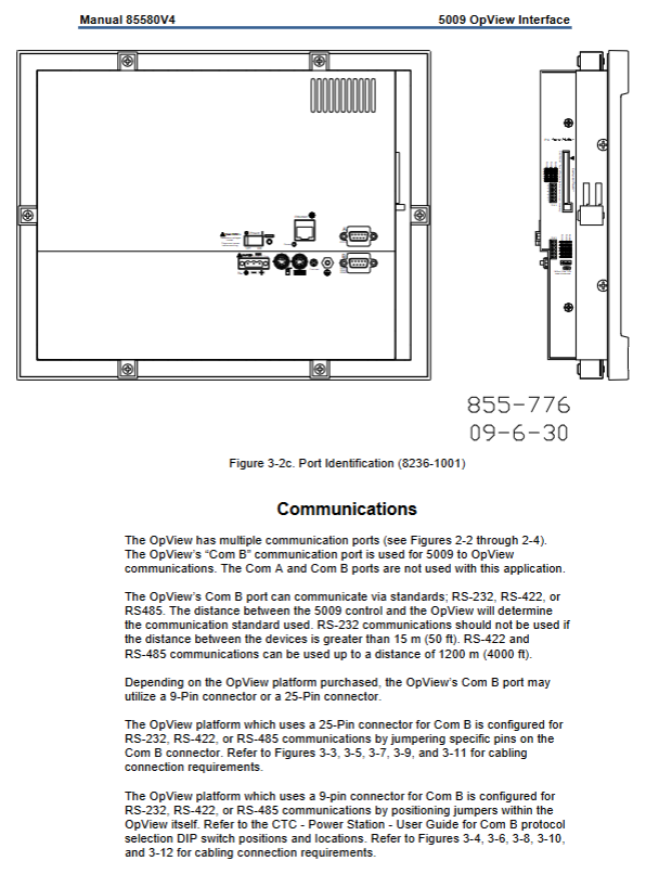
Communication port: OpView is connected to the J3 port of the 5009 control system SIO module through the Com B port
Communication protocol: Supports RS-232, RS-422, RS-485 standards, protocol selection depends on device distance
Maximum distance port configuration for communication protocol
RS-232 15m (50ft) 25 pin/9-pin Com B port, wire according to corresponding pins
RS-422 1200m (4000ft) 25 pin port requires short circuiting of specific pins, 9-pin port is configured through DIP switch
RS-485 1200m (4000ft) 25 pin port requires short circuiting of specific pins, 9-pin port configured through DIP switch
Default communication parameters: baud rate 9600, no checksum, data bit 8, stop bit 1, consistent with the 5009 control system port settings
(3) Printer and Initial Settings
Printer settings: Connect the parallel printer to the OpView parallel port, use standard IBM parallel cables, configure protocols and communication parameters to match
Initial startup: After the device is powered on, perform a diagnostic test (which takes several minutes), and display the main menu after the diagnosis is successful; When communication is lost, wait for 20 minutes before displaying the application screen
Time and date calibration: Enter the password through the main menu "CONFIGURE PASSWORD" and enter the application manager settings. The formats are "hour: minute: second" and "day: month: year"
Operation steps
(1) General operating rules
Operation method: Touch screen operation, button selection will change brightness or color to confirm response
Unit display: Consistent with the units configured in the programming mode of the 5009 control system (such as displaying KW or MW as load)
Communication loss handling: The screen displays "LOST Communication", which allows browsing but cannot issue commands. The 5009 control system will generate an alarm, and the alarm needs to be reset to receive the set value after communication is restored
Local/Remote Switching: After configuring 5009, the main menu and dynamic/trend menu display switching buttons, and all screens (except trend screens) display status indicators
(2) Special function operation
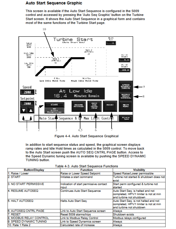
Turbine Start: Select the start mode (Idle/Rated, Auto Start Sequence, etc.) through the "Turbine Start" screen, click "START" to issue the start command, and monitor the speed increase status
Turbine operation: Adjust the speed, extraction, and other settings on the "Turbine Run" screen, enable/disable frequency control, synchronizers, and other functions
Controlled Shutdown: Start the shutdown sequence through the "Controlled Shutdown" screen, and click "ABORT" to abort the shutdown
Valve Calibration: Enter the calibration password (1111), meet the permission conditions such as shutdown state and speed<1000RPM, adjust the valve opening through the "Valve Calibration" screen, and click "SAVE CALIBRATION" to save
PID adjustment: Enter the "PID Control" screen to view the output and set values of each PID, and enter the dynamic adjustment password to modify the proportional, integral, and derivative parameters
Overspeed Test: Perform electrical overspeed (TEST 5009 TRIP) or external overspeed (TEST ExternalRNAL TRIP) test on the "Overspeed Test" screen. If the set value is not adjusted within 60 seconds during the test, it will automatically terminate
Alarm Log: View active alarms (red with asterisks) through the "Alarm Log" screen, click "ALM ACK" to confirm, "RESET" to reset, "CLEAR" to clear, and support printer output logs
(3) Permission management
The operation permissions are divided into three levels, and access is required by entering the corresponding password through the pop-up keyboard
Permission level, password, core operation permissions
SUPVAR level 1113 access application manager, configure OpView
Calibration level 1111 dynamically adjusts PID parameters and valve calibration
5009 level 5009 basic monitoring, setting value adjustment, mode switching
It is recommended to restore permissions to level 5009 during normal operation to prevent unauthorized operations
Password information and product support
(1) Password details
SUPVAR Level Password:1113, Used to access the application manager and configure OpView system parameters
Tuner/Valve Calibration Level Password:1111, Used for dynamically adjusting controller parameters and valve calibration operations
5009 Level Password:5009, Used for daily basic operations, such as parameter viewing and issuing regular commands
- YOKOGAWA
- Reliance
- ADVANCED
- SEW
- ProSoft
- WATLOW
- Kongsberg
- FANUC
- VSD
- DCS
- PLC
- man-machine
- Covid-19
- Energy and Gender
- Energy Access
- Renewable Integration
- Energy Subsidies
- Energy and Water
- Net zero emission
- Energy Security
- Critical Minerals
- A-B
- petroleum
- Mine scale
- Sewage treatment
- cement
- architecture
- Industrial information
- New energy
- Automobile market
- electricity
- Construction site
- HIMA
- ABB
- Rockwell
- Schneider Modicon
- Siemens
- xYCOM
- Yaskawa
- Woodward
- BOSCH Rexroth
- MOOG
- General Electric
- American NI
- Rolls-Royce
- CTI
- Honeywell
- EMERSON
- MAN
- GE
- TRICONEX
- Control Wave
- ALSTOM
- AMAT
- STUDER
- KONGSBERG
- MOTOROLA
- DANAHER MOTION
- Bentley
- Galil
- EATON
- MOLEX
- Triconex
- DEIF
- B&W
- ZYGO
- Aerotech
- DANFOSS
- KOLLMORGEN
- Beijer
- Endress+Hauser
- schneider
- Foxboro
- KB
- REXROTH
- YAMAHA
- Johnson
- Westinghouse
- WAGO
- TOSHIBA
- TEKTRONIX
- BENDER
- BMCM
- SMC
- HITACHI
- HIRSCHMANN
- XP POWER
- Baldor
- Meggitt
- SHINKAWA
- Other Brands
- UniOP
- KUKA
- IBA
- Beckhoff
- ADLINK
-
Beckhoff CX1100-0910 - Power Supply Module
-
Beckhoff C5210-0010 - Communication Module C5210
-
BECKHOFF KL1352 - Bus Terminal SET OF 2 FREE FAST SHIP
-
Beckhoff EL3058 - 8 x analog input single ended 4...20mA 85惟 shunt 12bit
-
Beckoff CX1100-0920 - UPS Module 24VDC (US SELLER) * *
-
BECKHOFF C6920-0000 - C69200000 PLC Moudule
-
Beckhoff CX5120-0115 - CPU controller module CX5120-0115
-
Unknown 15F5C1E-Y50A - Of Frequency Converters
-
Beckhoff AX5118-0000-0200 - Servo Drive HTP0
-
BECKHOFF AX5106-0000-0200 - Servo Drive
-
Beckhoff CX5240-0175 - Module (free) #U2327D YG
-
Beckhoff CP6607-0001-0000 - Compact PC Panel Economy Installation Operator 5,7 "
-
Beckhoff EP3744-0041 - 2022 EP37440041 Module
-
Beckhoff CP6209-0001-0020 - 6.5" PC Touch Screen Control Panel 24VDC
-
Beckhoff CX9020-0111 - /U900 +8x+2xEL3121+1x EL9410+3xEL1008+1x EL2008 Set
-
Beckhoff C6525-1030-0050 - Industrial PC
-
Beckoff CX1100-0920 - UPS Module 24VDC (US SELLER)
-
Beckhoff CX5010-0120 - CX5010 Processor Intel Atom Z510 B24
-
Siemens 6FC5203-0AF04-1BA1 - Operation Panel
-
Beckhoff CX5230-0175 - / 000029724 Embedded PC / Industrial PC on Rail
-
Beckhoff CP3916-0000 - industrielles Anzeige- und Bedienterminal
-
BECKHOFF CX1500-M310 - CX1000-N000 CX1000-0011 CX1000-C00L CX1100-0002 PLC Module
-
Beckhoff EL1872 - 16-channel digital input terminal
-
BECKHOFF EP2318-0001 - module
-
Beckhoff CX9020-0110 - Basic CPU Module
-
Beckhoff EL2564 - EtherCAT Terminal, 4-channel LED output, 5鈥?8VDC, 4A, RGBW
-
Beckhoff CX5130-0155 - /000105637 Automation Embedded PC
-
B&R 400 - Power Control Panel Rev D0 24 VDC
-
Beckhoff CX2020-0155 - module
-
Beckhoff CX9020-0115 - PLC Module
-
BECKHOFF EL6695 - PLC EL 6695
-
BECKHOFF EL7047 - PLC Modules
-
Beckhoff CX1000-0012 - Control HW 2.2 + CX1500-M310 + CX1000-C00L + CX1100-0002+
-
Beckhoff C6920-1039-0030 - control cabinet industrial PC CPU Celeron 1.90 GHz, 2 cores
-
BECKHOFF CX1100-0910 - PLC Module#
-
Beckhoff IL2301-B318-0000 - Coupler Box 4 Channel Digital Input |
-
Beckhoff CX7080 - Module
-
Beckhoff C6930-0060 - Industrial PC
-
Beckhoff CP7902-1060-0000 - Touchscreen 15 " CP7902
-
beckhoff CX9020-0111 - Controller module or UPS
-
Beckhoff CX8091 - PLC Module CX8091
-
Beckhoff C6640-1008-0030 - Control Cabinet Industrial PC
-
BECKHOFF CX1100-0920 - module
-
Beckhoff C9900-M921 - see pictures
-
BECKHOFF CP6829-0001-0000 - Touch Panel
-
BECKHOFF C6930-0060 - Industrial Computer
-
BECKHOFF CX8050 - PLC module
-
Beckhoff CP6202-0021-0020 - Touch Screen #
-
BECKHOFF AM3031-0C20-0000 - SERVO MOTOR
-
Unknown BCH1302N11A1C - Servo motor
-
Beckhoff EL2502 - 2-channel pulse width output terminal
-
Beckhoff EL6731 - Profibus Master / *Rev: 0025
-
Beckhoff CP3918-0010 - Control Panel
-
BECKHOFF CP2915-0010 - [24 MONTH WARRANTY] Control Panel
-
Beckhoff AX5203-0000-0202 - Servo Drive
-
Schneider TSXDSY64T2K - PLC OUTPUT MODULE
-
Beckhoff EP4174-0002 - Module-
-
Beckhoff IL2302-B318-0000 - Profibus Box
-
Beckhoff CP6709-0001-0000 - Touchpanel
-
BECKHOFF CX2030-0123 - Controller
-
Beckhoff CX9020-0111 - Processor Module
-
Beckhoff CX1020-0000 - CX Basic CPU Module
-
Beckhoff AX2003-AS - Servo Drive HTP0
-
Beckhoff C6240-1052-0040 - 4-086-06-3073 Industrial Computer CB1052-0003
-
Beckhoff EL1918 - 8 xTwinSAFE Input
-
Beckhoff AM8072-0R20-0000 - Servomotor
-
BECKHOFF AM8021-1B21-0000 - servo motor #T882 YS
-
Beckhoff EL6224 - 4 X Terminal IO-LINK
-
Beckhoff CX5140-0135 - embedded PC with Intel Atom processor 4 GB HW 3.6
-
Beckhoff CP7201-1000-0000 - Panel PC #
-
Beckhoff CX5130-0121 - Embedded-PC 4GB CPU Module HW 2.5 Industrial PC
-
Beckhoff AM8022-0D41-1002 - Servomotor
-
BECKHOFF CX2030-0130 - Module
-
BECKHOFF EL1872 - 16-channel digital input terminal
-
Unknown GXMMW.A203P33 - 1pc encoder
-
Beckhoff EL6631-0000 - EtherCAT Terminal 2-Port EL 6631
-
BECKHOFF C6925-0030 - Industrial Computer
-
Beckhoff CX8190 - A Module
-
BECKHOFF CX2040-0135 - CX2040-0135/000000927 CPU BASE MODULE i7 2715QE 2.1GHz --
-
BECKHOFF KL6023-0000 - Wireless adapter
-
Saia Burgess PCD7.F700 - PCD7F700 Communication Module
-
Beckhoff CX5130-0112 - CPU Module
-
BECKHOFF CX1020-N010 - CX1020-N000 CX1020-0111 CX1100-0004 EL2008 EL3064 EL4004
-
Beckhoff EP1819-0021 - A Module
-
Beckhoff CX2030-0120 - / 4gb with CX2100 0004
-
B&R X20-XC-0292 - Automation Powerlink Ethernet Bus Controller Module
-
Beckhoff BK3110 - One PLC Module
-
BECKHOFF KL3222 - PLC Module
-
BECKHOFF CX1500-M310 - CX1000-N000 CX1000-0011 CX1000-C00L CX1100-0002 PLC MODULE
-
Beckhoff CP3918-0010 - Control Panel
-
Beckhoff CX2030-0100-1002 - /4GB + CX2100 + CX2550 + CX2500-0060 + SSD
-
Beckhoff EP1816-0008 - PLC Module
-
Beckhoff CX5130-0112 - Module
-
Beckhoff Cx1500-m750 - CPU Hw: 1.4
-
BECKHOFF AX5112-0000-0200 - AX511200000200 Servo Driver
-
Beckhoff EL3751 - EtherCAT Terminal 1 Channel Analog Input Multifunction 24 Bit
-
Beckhoff CX1100-0002 - Power Supply Module
-
Beckhoff CP3916-1016-0010 - Control Panel
-
BECKHOFF CX9001-1101 - #NAME?
-
Beckhoff EP3174-0002 - EtherCAT Box Module
-
Beckhoff C6030-0070 - servo drive
-
Beckhoff CX2020-0120 - /4GB CPU, CX2100-0904, 3x EL6900, EL1904, 16GB Memory
-
BECKHOFF C6110 - BOX-PC 113608
-
BECKHOFF EK1914 - module #P
-
Beckhoff C6140 - Ipox IP-4GVI63 + CH7009A_DVI_TV + SIEMENS A5E00369843 + WD800AAJB
-
Beckhoff CX5020-0111 - controller Good quality
-
BECKHOFF C6015-0010 - / 6559380 ULTRA-COMPACT INDUSTRIAL PC ()
-
Beckhoff AX5203-0000-0200 - PLC module
-
Beckhoff EL2872 - 16-channel digital output terminal
-
BECKHOFF C3640-0000 - Panel Industrial PC 100/240VAC 128MB E0122L
-
Beckhoff CX8031 - Module
-
Beckhoff CX5020-0120-1002 - PLC module#
-
Beckhoff C6140 - M845B + SIEMENS A5E00369843 + C9900_A159_1 + AUTOMATA CAN PCI 1N
-
BECKHOFF AX5112-0000-0200 - Servo Drive*ie
-
B&R ECPA42-01 - Analog Output Module 4-Channel, +/- 10V Output Signal, 20mA Max
-
Beckhoff EL6631-0010 - PLC Module
-
BECKHOFF C6930-0070 - CONTROL CABINET INDUSTRIAL PC
-
BECKHOFF AX5112-0000-0200 - AX511200000200 Servo Driver
-
BECKHOFF EK9000 - Programmable Logic Controller Module EK9000 EK9000
-
BECKHOFF C6920-1028-0000 - Industrial computer
-
Beckhoff CX2030-0120 - controller Module
-
Beckhoff BX8000-0000 - Bus Terminal Controller HW 4.4
-
B&R 3NC154.60-2 - Positioning Module#
-
BECKHOFF CX1020-0122 - PLC module
-
Beckhoff AM3032-0D40-0000 - Servo Motor
-
BECKHOFF CX5020-0111 - CPU Module CX5020-0111
-
Beckhoff CB1051 - G5 Motherboard
-
BECKHOFF KL2641 - 1-channel relay output terminal

K-JIANG

Add: Jimei North Road, Jimei District, Xiamen, Fujian, China
Tell:+86-15305925923