
K-WANG


WOODWARD VariStroke-I (VS-I) electro-hydraulic actuator
WOODWARD VariStroke-I (VS-I) electro-hydraulic actuator
Basic Information
Type: Installation, Operation, and Maintenance Manual for VS-I Electro Hydraulic actuator
Applicable scenarios: Designed specifically for precise control of steam turbine valves, suitable for fields such as electricity and industrial power
Core value: Provide full lifecycle guidance from product recognition, installation, configuration to maintenance, ensuring safe and stable operation of equipment
Core safety requirements
(1) Warning definition and protection principles
Danger (DANGER): Failure to avoid causing death or serious injury
Warning: Failure to avoid may result in death or serious injury
CAUTION: Failure to avoid may result in minor or moderate injury
Notice: May only cause property damage
Important: Operation tips or maintenance recommendations
(2) Key safety measures
Anti static protection: Release human static electricity before contacting the equipment, avoid non anti-static materials from approaching the circuit board, and do not touch PCB components
Explosion proof compliance: Some models are suitable for Class I, Div.1/2, ATEX Zone 1/2 and other hazardous areas, and wiring must comply with corresponding specifications
Personal protection: PPE such as goggles, hearing protection equipment, helmets, gloves, and safety boots should be worn during operation
High pressure/overspeed protection: The hydraulic system needs to be equipped with independent overpressure protection, and the steam turbine needs to be equipped with an independent overspeed shutdown device
Live operation restrictions: It is prohibited to plug or unplug power supplies, modules, or cables with power in hazardous areas
(3) Compliance requirements
Key requirements for the scope of application of compliance standards
ATEX Directive 2014/34/EU Zone 1/2 Zone 1:II 2 G Ex db IIB T4 Gb; Zone 2:II 3 G Ex nA IIC T4 Gc
CSA Class I, Div.1/2 is applicable to Canada and the United States, Groups A-D T4
IECEx Zone 1/2 international explosion-proof certification, Ex db IIB T4 Gb(Zone 1)
CE (EMC) complies with Directive 2014/30/EU in the EU region
Product specifications and structure
(1) Core specification parameters
Category key parameter details
Physical parameters aperture 4/5/6/8/10 inches (100/127/150/200/250mm)
Rod diameter 1.75/2.5/3.5/4.5 inches (corresponding to aperture)
The electronic travel is adjustable, and the maximum mechanical travel depends on the model
Electrical parameters: Supply voltage 18-32Vdc (nominal 24Vdc), steady-state current 2.3A, transient 10A (100ms)
Input signal 2-channel redundant 4-20mA demand signal (input impedance 200 Ω)
Output signal 1 channel 4-20mA position feedback (load ≤ 500 Ω), 4 channels discrete output (0.5A/32Vdc)
Position sensor integrated with MLDT (magnetostrictive linear displacement sensor), accuracy ± 0.04%
Hydraulic parameters: minimum working pressure of 5.5 bar (80 psi), maximum working pressure of 34.5 bar (500 psi)
Oil type: petroleum based hydraulic oil or fire-resistant hydraulic oil (such as Fyrquel EHC)
The oil temperature is continuously between 15-70 ℃ (59-158 ° F)
Cleanliness requirements ISO 4406 code 20/18/16 or higher
Environmental parameters Operating temperature ambient: -40 to 85 ℃ (-40 to 185 ° F)
Protection level IP66 (IEC 60529)
Vibration/impact complies with MIL-STD 810F/G standard
Performance parameter positioning accuracy ± 1% full stroke
Repetitive accuracy ± 0.5% full stroke
Temperature drift MLDT: 0.04%/℃
Failure protection servo valve reset spring+optional spring assist to ensure valve closure
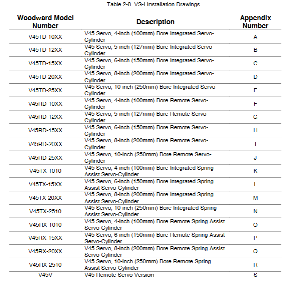
(2) Product structure type
Integrated: servo valve, hydraulic cylinder, electronic drive module integrated design, easy installation, suitable for spacious scenarios
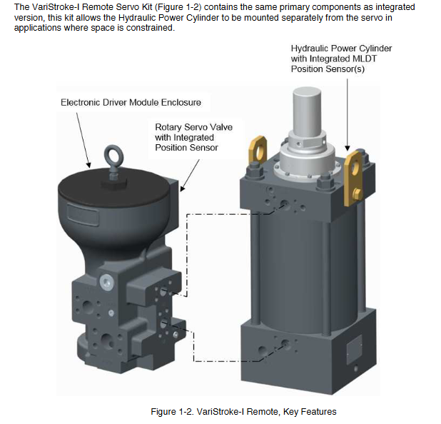
Remote: The servo valve and hydraulic cylinder are installed separately, with a maximum distance of 3m, suitable for limited space scenarios, and attention should be paid to pipeline pressure loss
Remote Servo Only: Only provides servo valves and electronic drive modules, compatible with user's own hydraulic cylinder (must meet position sensor requirements)
Installation process
(1) Preparation before installation
Receiving inspection: Check the appearance of the equipment for any damage, and verify that the model, serial number, and order are consistent
Unpacking requirements: Keep the hydraulic and electrical interface protective covers until they are removed during installation
Environmental preparation: Ensure that the installation area is free of pollutants, away from high temperature sources (such as uninsulated steam pipelines), and reserve maintenance space
(2) Mechanical installation
Installation orientation: The hydraulic cylinder can be installed at any angle, and the servo valve must not be inverted (vertical installation is recommended)
Bolt torque: Select the bolt grade (10.9 grade) according to the aperture, with a torque range of 50-400N · m (refer to Table 3-1 for details)
Lifting requirements: Use the equipment's built-in lifting ears for vertical transportation, and prohibit lifting the entire equipment solely through servo valve lifting ears
(3) Hydraulic connection
Pipeline requirements: Integrated type requires connection of oil supply (1.25-inch SAE Code 61 flange) and return oil (1.5-inch SAE Code 61 flange); Remote additional control port (1.0-inch SAE Code 61 flange)
Pipeline flushing: Thoroughly flush the hydraulic pipeline before installation to prevent impurities from entering the servo valve
Connection torque: Oil supply/return interface bolt torque 34-61N · m, control port 25-35N · m
(4) Electrical connection
Power Connection: Supports single power supply or dual redundant power supply, cable specification 1.5-2.5mm ² (12-16AWG), maximum wiring distance 30m
Signal connection: Shielded twisted pair cables are used for analog signals, with cable specifications ranging from 0.14-1.5mm ² (16-24AWG), and the shielding layer is grounded at one end
Grounding requirements: PE grounding (2.5mm ² green/yellow cable) and EMC grounding (>3mm ², length<46cm), torque 5.1N · m
Service Tools and Calibration Configuration
(1) Service tool installation
System requirements: Windows 7/Vista SP1/XP SP3 (32/64 bit),. NET Framework 4.0, 1GHz CPU, 512MB RAM
Installation method: Download the installation package (9927-2177 series) through the accompanying CD or Woodward official website
Connection method: Connect the device service port through RS-232 serial port, no serial port required, USB to serial converter (recommended 8928-1151 kit)
(2) Calibration process
Calibration prerequisite: Reduce the simulated demand signal to 0mA or disconnect the operation enable, and clear all fault alarms
Step 1- Stability setting: Enter the hydraulic oil supply pressure (bar), set the manual/running sleep rate, and soft seal parameters
Step 2- Travel Calibration: Optional "Find Minimum Travel" or "Find Minimum+Maximum Travel". After calibration, the minimum offset and maximum stop position can be adjusted
Save Calibration: After completing the calibration, click "Save Calibration" to ensure that the parameters are effective
(3) Core configuration function
Input configuration: Select the demand signal mode (single channel/dual channel average/dual channel low/dual channel high), set the enable switch for operation
Output configuration: Configure alarm/shutdown relay output (NO/NC), analog output function (demand signal/actual position)
Advanced configuration: Adjust bandwidth (response speed), jitter (overcome valve sticking), Silk Buster (regularly flush servo valve impurities)
Linearization configuration: 11 point linearization table, compensating for valve flow nonlinearity, needs to be set in ascending numerical order
Maintenance and troubleshooting
(1) Common troubleshooting
Typical causes and troubleshooting measures for fault types
The device shutdown operation enable is not activated. Check that the operation enable circuit is closed and confirm that it is configured as "Used"
If the demand signal exceeds the range (<2mA or>22mA), check the analog signal wiring and adjust the signal to 4-20mA
Key fault triggers (such as position sensor failure) can be checked through service tools to access alarm logs and identify corresponding components
The positioning accuracy deviation is large, and the cleanliness of the hydraulic oil does not meet the standard. Check the cleanliness of the oil and replace the filter element
Compensate for improper needle valve settings, recalibrate stroke, and adjust stability parameters
Connecting rod misalignment>5 °, correct connecting rod installation to ensure deviation ≤ 5 °
No response (no alarm). The power supply is not connected or the voltage is too low. Check the power supply voltage (18-32Vdc) and verify the wiring
Connect the communication fault inspection service tool and restart the device
Replace the corresponding aperture shaft seal kit (refer to Table 7-1) for hydraulic leakage seal wear and tear
The pipeline interface is not tightened. Re tighten the interface bolts according to the specified torque
(2) Maintenance operation
Shaft seal replacement: Select the corresponding kit (4-inch: 8935-1216-10; 10 inch: 8935-1216-25) according to the aperture, and install the seal strictly according to the diagram
Servo valve/hydraulic cylinder replacement: Contact Woodward authorized service organization and refer to manual 26836 to follow the replacement process
Long term storage: Clean the surface of the equipment, remove the hydraulic oil, seal the interface, store in an environment temperature of -40 to 85 ℃, avoid moisture
- YOKOGAWA
- Reliance
- ADVANCED
- SEW
- ProSoft
- WATLOW
- Kongsberg
- FANUC
- VSD
- DCS
- PLC
- man-machine
- Covid-19
- Energy and Gender
- Energy Access
- Renewable Integration
- Energy Subsidies
- Energy and Water
- Net zero emission
- Energy Security
- Critical Minerals
- A-B
- petroleum
- Mine scale
- Sewage treatment
- cement
- architecture
- Industrial information
- New energy
- Automobile market
- electricity
- Construction site
- HIMA
- ABB
- Rockwell
- Schneider Modicon
- Siemens
- xYCOM
- Yaskawa
- Woodward
- BOSCH Rexroth
- MOOG
- General Electric
- American NI
- Rolls-Royce
- CTI
- Honeywell
- EMERSON
- MAN
- GE
- TRICONEX
- Control Wave
- ALSTOM
- AMAT
- STUDER
- KONGSBERG
- MOTOROLA
- DANAHER MOTION
- Bentley
- Galil
- EATON
- MOLEX
- Triconex
- DEIF
- B&W
- ZYGO
- Aerotech
- DANFOSS
- KOLLMORGEN
- Beijer
- Endress+Hauser
- schneider
- Foxboro
- KB
- REXROTH
- YAMAHA
- Johnson
- Westinghouse
- WAGO
- TOSHIBA
- TEKTRONIX
- BENDER
- BMCM
- SMC
- HITACHI
- HIRSCHMANN
- XP POWER
- Baldor
- Meggitt
- SHINKAWA
- Other Brands
- UniOP
- KUKA
- IBA
- Beckhoff
- ADLINK
-
Beckhoff CX1100-0910 - Power Supply Module
-
Beckhoff C5210-0010 - Communication Module C5210
-
BECKHOFF KL1352 - Bus Terminal SET OF 2 FREE FAST SHIP
-
Beckhoff EL3058 - 8 x analog input single ended 4...20mA 85惟 shunt 12bit
-
Beckoff CX1100-0920 - UPS Module 24VDC (US SELLER) * *
-
BECKHOFF C6920-0000 - C69200000 PLC Moudule
-
Beckhoff CX5120-0115 - CPU controller module CX5120-0115
-
Unknown 15F5C1E-Y50A - Of Frequency Converters
-
Beckhoff AX5118-0000-0200 - Servo Drive HTP0
-
BECKHOFF AX5106-0000-0200 - Servo Drive
-
Beckhoff CX5240-0175 - Module (free) #U2327D YG
-
Beckhoff CP6607-0001-0000 - Compact PC Panel Economy Installation Operator 5,7 "
-
Beckhoff EP3744-0041 - 2022 EP37440041 Module
-
Beckhoff CP6209-0001-0020 - 6.5" PC Touch Screen Control Panel 24VDC
-
Beckhoff CX9020-0111 - /U900 +8x+2xEL3121+1x EL9410+3xEL1008+1x EL2008 Set
-
Beckhoff C6525-1030-0050 - Industrial PC
-
Beckoff CX1100-0920 - UPS Module 24VDC (US SELLER)
-
Beckhoff CX5010-0120 - CX5010 Processor Intel Atom Z510 B24
-
Siemens 6FC5203-0AF04-1BA1 - Operation Panel
-
Beckhoff CX5230-0175 - / 000029724 Embedded PC / Industrial PC on Rail
-
Beckhoff CP3916-0000 - industrielles Anzeige- und Bedienterminal
-
BECKHOFF CX1500-M310 - CX1000-N000 CX1000-0011 CX1000-C00L CX1100-0002 PLC Module
-
Beckhoff EL1872 - 16-channel digital input terminal
-
BECKHOFF EP2318-0001 - module
-
Beckhoff CX9020-0110 - Basic CPU Module
-
Beckhoff EL2564 - EtherCAT Terminal, 4-channel LED output, 5鈥?8VDC, 4A, RGBW
-
Beckhoff CX5130-0155 - /000105637 Automation Embedded PC
-
B&R 400 - Power Control Panel Rev D0 24 VDC
-
Beckhoff CX2020-0155 - module
-
Beckhoff CX9020-0115 - PLC Module
-
BECKHOFF EL6695 - PLC EL 6695
-
BECKHOFF EL7047 - PLC Modules
-
Beckhoff CX1000-0012 - Control HW 2.2 + CX1500-M310 + CX1000-C00L + CX1100-0002+
-
Beckhoff C6920-1039-0030 - control cabinet industrial PC CPU Celeron 1.90 GHz, 2 cores
-
BECKHOFF CX1100-0910 - PLC Module#
-
Beckhoff IL2301-B318-0000 - Coupler Box 4 Channel Digital Input |
-
Beckhoff CX7080 - Module
-
Beckhoff C6930-0060 - Industrial PC
-
Beckhoff CP7902-1060-0000 - Touchscreen 15 " CP7902
-
beckhoff CX9020-0111 - Controller module or UPS
-
Beckhoff CX8091 - PLC Module CX8091
-
Beckhoff C6640-1008-0030 - Control Cabinet Industrial PC
-
BECKHOFF CX1100-0920 - module
-
Beckhoff C9900-M921 - see pictures
-
BECKHOFF CP6829-0001-0000 - Touch Panel
-
BECKHOFF C6930-0060 - Industrial Computer
-
BECKHOFF CX8050 - PLC module
-
Beckhoff CP6202-0021-0020 - Touch Screen #
-
BECKHOFF AM3031-0C20-0000 - SERVO MOTOR
-
Unknown BCH1302N11A1C - Servo motor
-
Beckhoff EL2502 - 2-channel pulse width output terminal
-
Beckhoff EL6731 - Profibus Master / *Rev: 0025
-
Beckhoff CP3918-0010 - Control Panel
-
BECKHOFF CP2915-0010 - [24 MONTH WARRANTY] Control Panel
-
Beckhoff AX5203-0000-0202 - Servo Drive
-
Schneider TSXDSY64T2K - PLC OUTPUT MODULE
-
Beckhoff EP4174-0002 - Module-
-
Beckhoff IL2302-B318-0000 - Profibus Box
-
Beckhoff CP6709-0001-0000 - Touchpanel
-
BECKHOFF CX2030-0123 - Controller
-
Beckhoff CX9020-0111 - Processor Module
-
Beckhoff CX1020-0000 - CX Basic CPU Module
-
Beckhoff AX2003-AS - Servo Drive HTP0
-
Beckhoff C6240-1052-0040 - 4-086-06-3073 Industrial Computer CB1052-0003
-
Beckhoff EL1918 - 8 xTwinSAFE Input
-
Beckhoff AM8072-0R20-0000 - Servomotor
-
BECKHOFF AM8021-1B21-0000 - servo motor #T882 YS
-
Beckhoff EL6224 - 4 X Terminal IO-LINK
-
Beckhoff CX5140-0135 - embedded PC with Intel Atom processor 4 GB HW 3.6
-
Beckhoff CP7201-1000-0000 - Panel PC #
-
Beckhoff CX5130-0121 - Embedded-PC 4GB CPU Module HW 2.5 Industrial PC
-
Beckhoff AM8022-0D41-1002 - Servomotor
-
BECKHOFF CX2030-0130 - Module
-
BECKHOFF EL1872 - 16-channel digital input terminal
-
Unknown GXMMW.A203P33 - 1pc encoder
-
Beckhoff EL6631-0000 - EtherCAT Terminal 2-Port EL 6631
-
BECKHOFF C6925-0030 - Industrial Computer
-
Beckhoff CX8190 - A Module
-
BECKHOFF CX2040-0135 - CX2040-0135/000000927 CPU BASE MODULE i7 2715QE 2.1GHz --
-
BECKHOFF KL6023-0000 - Wireless adapter
-
Saia Burgess PCD7.F700 - PCD7F700 Communication Module
-
Beckhoff CX5130-0112 - CPU Module
-
BECKHOFF CX1020-N010 - CX1020-N000 CX1020-0111 CX1100-0004 EL2008 EL3064 EL4004
-
Beckhoff EP1819-0021 - A Module
-
Beckhoff CX2030-0120 - / 4gb with CX2100 0004
-
B&R X20-XC-0292 - Automation Powerlink Ethernet Bus Controller Module
-
Beckhoff BK3110 - One PLC Module
-
BECKHOFF KL3222 - PLC Module
-
BECKHOFF CX1500-M310 - CX1000-N000 CX1000-0011 CX1000-C00L CX1100-0002 PLC MODULE
-
Beckhoff CP3918-0010 - Control Panel
-
Beckhoff CX2030-0100-1002 - /4GB + CX2100 + CX2550 + CX2500-0060 + SSD
-
Beckhoff EP1816-0008 - PLC Module
-
Beckhoff CX5130-0112 - Module
-
Beckhoff Cx1500-m750 - CPU Hw: 1.4
-
BECKHOFF AX5112-0000-0200 - AX511200000200 Servo Driver
-
Beckhoff EL3751 - EtherCAT Terminal 1 Channel Analog Input Multifunction 24 Bit
-
Beckhoff CX1100-0002 - Power Supply Module
-
Beckhoff CP3916-1016-0010 - Control Panel
-
BECKHOFF CX9001-1101 - #NAME?
-
Beckhoff EP3174-0002 - EtherCAT Box Module
-
Beckhoff C6030-0070 - servo drive
-
Beckhoff CX2020-0120 - /4GB CPU, CX2100-0904, 3x EL6900, EL1904, 16GB Memory
-
BECKHOFF C6110 - BOX-PC 113608
-
BECKHOFF EK1914 - module #P
-
Beckhoff C6140 - Ipox IP-4GVI63 + CH7009A_DVI_TV + SIEMENS A5E00369843 + WD800AAJB
-
Beckhoff CX5020-0111 - controller Good quality
-
BECKHOFF C6015-0010 - / 6559380 ULTRA-COMPACT INDUSTRIAL PC ()
-
Beckhoff AX5203-0000-0200 - PLC module
-
Beckhoff EL2872 - 16-channel digital output terminal
-
BECKHOFF C3640-0000 - Panel Industrial PC 100/240VAC 128MB E0122L
-
Beckhoff CX8031 - Module
-
Beckhoff CX5020-0120-1002 - PLC module#
-
Beckhoff C6140 - M845B + SIEMENS A5E00369843 + C9900_A159_1 + AUTOMATA CAN PCI 1N
-
BECKHOFF AX5112-0000-0200 - Servo Drive*ie
-
B&R ECPA42-01 - Analog Output Module 4-Channel, +/- 10V Output Signal, 20mA Max
-
Beckhoff EL6631-0010 - PLC Module
-
BECKHOFF C6930-0070 - CONTROL CABINET INDUSTRIAL PC
-
BECKHOFF AX5112-0000-0200 - AX511200000200 Servo Driver
-
BECKHOFF EK9000 - Programmable Logic Controller Module EK9000 EK9000
-
BECKHOFF C6920-1028-0000 - Industrial computer
-
Beckhoff CX2030-0120 - controller Module
-
Beckhoff BX8000-0000 - Bus Terminal Controller HW 4.4
-
B&R 3NC154.60-2 - Positioning Module#
-
BECKHOFF CX1020-0122 - PLC module
-
Beckhoff AM3032-0D40-0000 - Servo Motor
-
BECKHOFF CX5020-0111 - CPU Module CX5020-0111
-
Beckhoff CB1051 - G5 Motherboard
-
BECKHOFF KL2641 - 1-channel relay output terminal

K-JIANG

Add: Jimei North Road, Jimei District, Xiamen, Fujian, China
Tell:+86-15305925923