
K-WANG


Woodward 723PLUS Digital Controller
Woodward 723PLUS Digital Controller
Describe
This manual introduces the hardware related content of the Woodward 723PLUS digital controller (models 9906-619, 9906-620, 9906-700), including general information, installation, control setpoint input, use of Servlink and Watch Window, product support and service options, etc. The controller is suitable for various application scenarios that require speed control.
General information
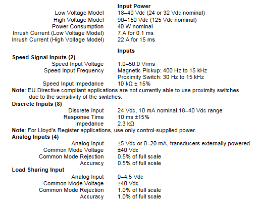
Application scenarios: It can adapt to various applications through programming. The hardware includes two speed inputs, supports two magneto electric sensors (MPUs) or proximity switches (such as for torsional filtering), as well as four analog inputs, three analog outputs, eight discrete inputs, and three discrete outputs, which can be used in load sharing systems. Its two LON channels can support related control functions.
Control options: Different models have different power input voltage requirements, and discrete input voltage provides switch command signals for control. There are also various other control options, such as proximity switch input suitable for low-frequency speed signals, 0-1mA output of instrument drivers, etc. The controller can be used in conjunction with proximity switches or magneto electric sensors with minimum frequency requirements.
Attachments: including handheld programmer (9907-205), SPM-A synchronizer, power output sensor, active power sensor, etc.
install
Scope: This includes general installation instructions for the 723PLUS controller, including power requirements, environmental precautions, location considerations, as well as unboxing, electrical connections, and installation inspection procedures.
Unpacking: Before handling the controller, it is necessary to read the relevant content on electrostatic discharge protection. When unpacking, be careful and check whether the controller is damaged. If there is any damage, immediately notify the shipper.
Power requirements: High voltage models require a 90-150Vdc voltage source, while low voltage models require an 18-40Vdc voltage source. To prevent damage to the controller, the input voltage range must not be exceeded. If battery power is used, an AC generator or other battery charging equipment must be equipped.
Location considerations: When selecting the installation location, factors such as ventilation, maintenance space, liquid and condensation prevention, electromagnetic interference prevention, and vibration prevention should be taken into account. The controller should not be installed on the prime mover, and the operating temperature range is -40 to+70 ° C (-40 to+158 ° F).
Specific installation requirements for marine use: The certification requirements for marine use types may change over time. In order to meet these requirements, all wiring, except for the part near the control connection terminal, must be inside metal conduits, and the control must be installed on a grounded metal mounting plate. It is also possible to meet attenuation requirements at specific installation locations or methods without additional special measures, but consultation with the shipyard is required.
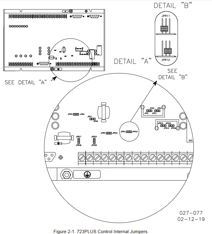
Internal jumpers: The 723PLUS controller has ten two position internal jumpers located at the top of the printed circuit board. If you need to change the jumpers, you need to read the electrostatic discharge protection content first, power off and wait before operating. Different jumpers have different default settings and functions.
Electrical connection: External wiring connection and shielding requirements should refer to relevant software manuals. All shielded cables must be twisted pair, signal lines should be shielded, and shielding layer connections should follow specific requirements. It also provides detailed instructions on the connection methods and precautions for power supply, analog output, actuator output, speed signal input, load sharing line input, discrete input, analog input, etc.
Installation inspection program: After installation, visual inspection (checking linkage devices, wiring, terminals, speed sensors, etc.) and grounding inspection are required to ensure that the resistance between each terminal of the controller and the chassis meets the requirements.
Serial port communication: The 723PLUS has two serial ports for communication, which can be configured into multiple types through software. When writing applications, it can be configured as a Modbus communication port and supports relevant protocols.
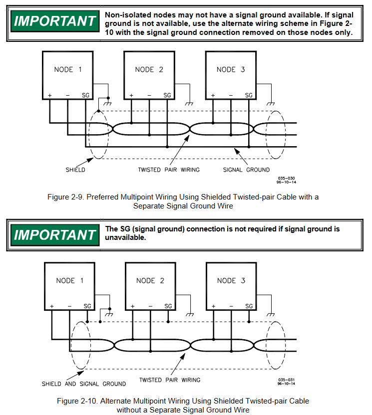
Terminal matching and grounding shielding: Different communication types (RS-422, RS-485) have different terminal matching requirements. RS-422 and RS-485 specifications require grounding wires when there are no other grounding paths between units. There are preferred and alternative wiring methods, and shielding and grounding must be handled correctly.
Control set point input
Overview: Due to differences in installation, system, and component tolerances, the 723PLUS controller must be adjusted for each system to achieve optimal performance. Setpoint inputs can be made through a handheld programmer or PC (using Watch Window software tools and Servlink software).
Handheld programmer and menu: The handheld programmer obtains power from the 723PLUS controller, connects to the RS-422 communication serial port of the controller, performs self check after power on, and displays application related information on the screen. The controller has a service menu and a configuration menu. The configuration menu needs to be entered when I/O is turned off (engine stopped), and the service menu can be directly entered through buttons. The operation menu and settings
Control set point input
Overview
Due to differences in installation environment, system, and component tolerances, the 723PLUS controller needs to be adjusted for specific systems to achieve optimal performance. Setpoint input can be completed through a handheld programmer or by connecting to a PC (using Watch Window software and Servlink software).
Handheld programmer and menu
Programmer connection and self-test
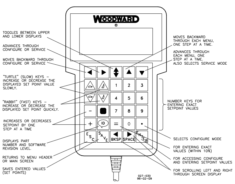
The handheld programmer (model 9907-205) obtains power from the 723PLUS controller and connects to the RS-422 communication serial port (J1 terminal) of the controller. When connecting, slightly loosen the right screw of the J1 port cover plate, rotate the cover plate clockwise to expose the 9-pin connector, and then firmly insert the programmer connector into J1.
After connecting the programmer to the controller, it will perform a power on self-test. After the self-test is completed, the screen will display two pieces of information related to the application. Press the ID key to switch between displaying the software's part number and version letter.
Menu type and access
Configure menu: It needs to be accessed while the engine is stopped. Press the corresponding button, and the screen will display "To select configure, press enter". After pressing the ENTER key, it will display "To shutdown I/O, press enter". Press the ENTER key again to enter. If the engine is running during this process, it will shut down due to controller I/O shutdown.
Service menu: Press the DOWN ARROW key to access without shutting down the engine.
Menu Operation
Move between menus: Use the LEFT ARROW and RIGHT ARROW keys.
To move between set points within the menu: use the UP ARROW and DOWN ARROW keys.
Return to menu title: Press ESC key.
Exit menu: Press the ESC key, and the configuration menu will automatically save the set points when exiting.
Setpoint adjustment
Arrange mode
Use the TURTLE UP or RABBIT UP keys to increase the set value, and the TURTLE DOWN or RABBIT DOWN keys to decrease the set value. The adjustment rate of the RABBIT key is about 10 times that of the TURTLE key, which is suitable for situations where a large adjustment value is required.
For settings that require the selection of TRUE or False, use the corresponding increase or decrease keys.
Use the+or - keys to gradually change integer values in the application software.
To enter a precise value, press the=key, enter the desired value, and then press the ENTER key, but the value must be within 10% of the existing value.
Save Setpoints
At any time, the SAVE key can be used to save the set points and transfer the new set point values to the EEPROM memory, which retains all set points even when the controller is powered off.
To prevent the loss of set values after the controller is powered off due to the failure to save the set points, which may damage the engine, it is necessary to save the set points before removing the controller power supply.
- YOKOGAWA
- Reliance
- ADVANCED
- SEW
- ProSoft
- WATLOW
- Kongsberg
- FANUC
- VSD
- DCS
- PLC
- man-machine
- Covid-19
- Energy and Gender
- Energy Access
- Renewable Integration
- Energy Subsidies
- Energy and Water
- Net zero emission
- Energy Security
- Critical Minerals
- A-B
- petroleum
- Mine scale
- Sewage treatment
- cement
- architecture
- Industrial information
- New energy
- Automobile market
- electricity
- Construction site
- HIMA
- ABB
- Rockwell
- Schneider Modicon
- Siemens
- xYCOM
- Yaskawa
- Woodward
- BOSCH Rexroth
- MOOG
- General Electric
- American NI
- Rolls-Royce
- CTI
- Honeywell
- EMERSON
- MAN
- GE
- TRICONEX
- Control Wave
- ALSTOM
- AMAT
- STUDER
- KONGSBERG
- MOTOROLA
- DANAHER MOTION
- Bentley
- Galil
- EATON
- MOLEX
- Triconex
- DEIF
- B&W
- ZYGO
- Aerotech
- DANFOSS
- KOLLMORGEN
- Beijer
- Endress+Hauser
- schneider
- Foxboro
- KB
- REXROTH
- YAMAHA
- Johnson
- Westinghouse
- WAGO
- TOSHIBA
- TEKTRONIX
- BENDER
- BMCM
- SMC
- HITACHI
- HIRSCHMANN
- XP POWER
- Baldor
- Meggitt
- SHINKAWA
- Other Brands
- UniOP
- KUKA
- IBA
- Beckhoff
-
ADLINK PCI-7433 - switch value acquisition card Isolated Digital Input Card
-
ADLINK PCI-9112 - 51-12252-0D20 Multi-Function Data Acquisition Card
-
ADLINK NUPRO-A301 REV:1.4 - industrial control motherboard PICMG Full-Size SBC
-
ADLINK 51-18502-0A10 - Frame Grabber Image Acquisition Interface Card
-
ADLINK PCI-7296 - 51-12009-0A50 PCB-I-E-925=6DX1 96-CH Parallel Digital I/O Board
-
ADLINK PCI-8132 GP A2 - Motion Control Card 2-Axis Servo & Stepper Controller
-
ADLINK PCI-7442 - switch quantity card data acquisition card 64-CH Isolated Card
-
ADLINK HPX-13S4 - baseboard PICMG 1.3 Passive Backplane Chassis Baseplate
-
ADLINK NuPRO-590 / NTC-567-ZM-F36 - Single Board Computer PCB-I-E-1853=9L21 Half-Size SBC
-
ADLINK PCIe-8332 - 16-axis plate Motion Control Hardware Card
-
ADLINK NuPRO-775 REV.B1 - motherboard Pentium 4 Full-Size PICMG SBC
-
ADLINK PXI-3920 - Embedded Controller 3U PXI cPCI System Intelligence Board
-
ADLINK PCI-8134 - driver card motion control card 4-Axis Controller Board
-
ADLINK HSL-DI32-M-N-011 / HSL-TB32-M-DIN - Digital Input & Base Module PLC Distributed I/O System
-
ADLINK PCI-6216V-206 / PCI-208V 009 - 16 CH 16bit analog output card
-
ADLINK NuPro-E330 - 51-41805-0A20 PCB Single Board Computer Host Board
-
ADLINK PCI-1622C - Card 8-Port RS-232/422/485 PCI Serial Communication Board
-
ADLINK PCIe-7432 - 51-18402-0A10 Carte PCIe Avec Plage D'Entrée Élevée Isolated DIO Card
-
ADLINK PCI-7250 - PCI Acquisition Card 8-CH Relay Output Isolated DI Card
-
ADLINK PCI-7230 - 32-CH Isolated Digital I/O Card
-
ADLINK PCI-8164 - PCB 4-Axis Motion Controller Card
-
ADLINK PCI-7854 - Collection card High-Speed Link Distributed Motion Controller
-
ADLINK NuPRO-935A/LV - industrial control computer motherboard Full-Size PICMG SBC
-
ADLINK IMB-M40H - motherboard IH61-AA4 1155 LGA1155 Micro-ATX Mainboard
-
ADLINK PCI-7248 - Linhua 51-12006-0A40 48-CH Parallel Digital I/O Card
-
ADLINK HPCI-14S12U - Linhua industrial computer baseboard Passive Backplane
-
ADLINK PCI-8132 Rev.A2 - 2-Axis Servo & Stepper Motion Controller Card
-
ADLINK ACL-8111 - ISA card Multi-Function DAQ Card
-
ADLINK ACL-8111 - ISA card Multi-Function Data Acquisition Board
-
ADLINK PCI-7200 REV.A3 - Digital I/O card 12MB/s High-Speed Parallel Digital I/O
-
ADLINK PCI-7296 REV.A3 - 96-CH High-Density Opto-Isolated DIO Card
-
ADLINK PCI-7434 - 64-CH Isolated Digital Output Card
-
ADLINK M-342 - atx motherboard Industrial PC Mainboard
-
ADLINK NuPRO-935ADV (A) 1.9 - CPU Board Intel Core 2 Quad CPU Q9500 2.83GHz PICMG Board
-
ADLINK NUPRO-935A/DV - motherboard dual network port 51-41802-0A10 CPU Board
-
ADLINK PCI-RTV24 - image capture card Analog Video Frame Grabber Board
-
ADLINK HPX-13S4 - device baseboard PICMG 1.3 Passive Backplane Chassis Baseplate
-
ADLINK PCI-8134A - control card 4-Axis Motion Controller Card
-
ADLINK ACL-7130 REV. B2 - industrial control capture card Isolated Digital I/O Board
-
ADLINK EBP-13E2 - Industrial Backplane Board Passive Backplane Baseboard
-
ADLINK NuPRO-935ADV (A) 1.9 - CPU Board Intel Core 2 Quad CPU Q9500 2.83GHz PICMG SBC
-
ADLINK PCI-8134A - motion control card 4-Axis Pulse-Train Controller Card
-
ADLINK PCI-9112 REV A.1 - Multi Function DA&C Board Data Acquisition Card
-
ADLINK 51-12001-0C20 - Circuit Board Multi-Function Data Acquisition Hardware
-
ADLINK PCI-7300A - 80-CH High-Speed Digital I/O Card
-
ADLINK PCI-7230 - 16-CH Isolated Digital Input Output Card
-
ADLINK DIN-814-GP - motion control module Interface Terminal Block
-
ADLINK NUPRO-A40H - 51-41807-1A20 Industrial Control Motherboard LGA1155
-
ADLINK PCI-7433 rev A2 - Isolated Digital Input Card
-
ADLINK NuPRO-780 - Pentium III 800 512 MB SBC NuPRO780 51-41309-0B2 Single Board Computer
-
ADLINK PCI-7853 / PCI-7854 - Acquisition card High-Speed Link Control Card
-
ADLINK NUPRO-852 / NUPRO-852LV - Industrial motherboard Full-Size PICMG CPU Board
-
ADLINK NuPRO-842LV/P - 51-41360-0B30 Industrial Motherboard Half-Size PICMG SBC
-
ADLINK PCI-FIW64 - 4/2 Channel IEEE1394B Image Capture Card Frame Grabber
-
ADLINK PCI-7851 Rev A1.1 - HSL system card High-Speed Link Master Controller
-
ADLINK PCI-7230 - 51-12003-0A50 card 32-CH Isolated Digital I/O Card
-
ADLINK NuPRO-841REV:1.0 - Industrial CPU Board Mainboard
-
ADLINK NuPRO-841 REV:1.0 - motherboard Industrial Control PC Mainboard
-
ADLINK PCI-8256 - 8-Axis Advanced Motion Control PCI Board
-
ADLINK PCI-6S / PCI6S - Backplane 6-Slot Passive Backplane Board
-
ADLINK PCI-7234 REV B3 - 32-CH Isolated Digital Output PCI Card
-
ADLINK PCI-8213 - HannStar MV-4 51-45003-0b4 Board
-
ADLINK PCI-7233 - 51-12004-0a20 board PCI7233 32-CH Isolated Digital Input Card
-
ADLINK PCI-7851 - 006 51-24003-0B20 High-Speed Link Master Motion Control Card
-
ADLINK PCI-7432 - 64-CH Isolated Digital I/O PCI Cards
-
ADLINK LPCI-3488 - Card Low Profile IEEE-488 GPIB Interface Card
-
ADLINK HPCI14S REV.B1 - industrial control computer base plate Passive Backplane
-
ADLINK NEON-1020 - Industrial camera Smart Camera Vision System
-
ADLINK PCI-7432 - Isolated Digital I/O PCI Card 64-CH
-
ADLINK Pcm-7250+ - 8-Ch Relay Outputs & 8-Ch Isolated DI Module PC/104
-
ADLINK CPCI-7841 - DUAL-PORT ISOLATED CAN INTERFACE CARD CompactPCI
-
ADLINK PCI-3488 / PCI-GPIB - PCI IEEE-488 GPIB Interface Card
-
ADLINK PCI-1711U - Card Multi-Function Data Acquisition Board
-
ADLINK NUPRO-A301 - REV:1.1 1.2 1.4 PICMG Full-Size Single Board Computer
-
Adlink DIN-50S-01 - PLOTECH 51-14024-0A40 50-pin Wiring Terminal Board
-
Chroma 52962 / 58183 - PXI Optical Spectrometer carrier adapter Card
-
ADLINK PCI-6208V - PCI DATA ACQUISITION & RECORDING CARD 8-CH Analog Output
-
ADLINK HSL-DI32-DB-N - Industrial Control Board Distributed Digital Input Module
-
ADLINK HSL-AO4-U - 4-CH HIGH SPEED LINK ANALOG OUTPUT MODULE Distributed I/O
-
ADLINK PCI-7396 - 0050 GP 51-12012-0B20 96-CH High-Speed Digital I/O Card
-
ADLINK NUPRO-935A/DV - 51-41802-0A10 motherboard Industrial CPU Single Board Computer
-
ADLINK PCI-9111 DG - Industrial Acquisition Card Multi-Function DAQ Card
-
ADLINK NuPRO-E315 - industrial computer motherboard Intel Atom SHB SBC
-
ADLINK NUPRO-406 REV:B1 - Industrial Control Motherboard Full-Size PICMG CPU Board
-
ADLINK NuPRO-E330 - motherboard Industrial Control System Host Board PICMG 1.3
-
ADLINK ACL-6128A 103 - 51-11002-1A4 2-CH Isolated Analog Output Card
-
XTRAMUS cPS-H325/AC - POWER SUPPLY NUSTREAMS 600 NETWORK TESTING EQUIPMENT Power Module
-
ADLINK DIN-814P-A4 - 51-14056-0A10 Terminal Block Motion Control Breakout Board
-
ADLINK TB-24P/24-01 - 24-Channel Card Terminal Breakout Board
-
ADLINK PCI-7251 - 51-12008-0A30 PCI7251 8-CH Relay Output Isolated Digital Input Card
-
Basler Electric DECS-250-CN1SN1N Automatic Voltage Regulator for Generator Excitation Control
-
ADLINK CPCI-6860A - 51-31310-OB10 industrial motherboard CompactPCI SBC
-
ADLINK AmITX-SL-G-H110 - 51-7A104-0A30 Mini-ITX Industrial Motherboard
-
ADLINK PXI-2005-003 - CPCI Industrial PC Data Acquisition Card Multi-Function DAQ
-
ADLINK DININ-814M - 51-14032-0A3D SCSI-100P cable connection Interface Terminal Board
-
ADLINK CPCI-3920NA/C2D15/M1G - 3U CompactPCI Intel Core 2 Duo Single Board Computer
-
ADLINK PCIE-8560 - 51-18014-0A20 Communication Card High Speed DAQ
-
ADLINK PCI-C154+ - Motion Control Card 4-axis Motion Controller Board
-
ADLINK PCI-RTV24 - image capture card Analog Video Frame Grabber
-
ADLINK NuPRO-842LV/P - 51-41360-0B30 Industrial Motherboard CPU Board
-
ADLINK cBP-3208/3208R - CPCI Board 3U 8-Slot CompactPCI Backplane
-
ADLINK PCI-8164 - 4-Axis Motion Controller PCI Card 51-12406-0A40
-
ADLINK PCIe-GIE64+ - 4-CH GigE Vision PoE+ Frame Grabber Video Capture Card
-
ADLINK CPCI-6860 / 6860A - CompactPCI Dual Xeon Single Board Computer
-
ADLINK IEC-915GV - REV 1.1 Industrial motherboard CPU Board
-
ADLINK ND-6520 - Technology RS-232 to RS-422RS-485 Converter NuDAM Module
-
ADLINK RTV-24 / PCI-MP4S - 51-12519-1C30 4-Channel Real Time Video Capture Board
-
ADLINK cPCI-6910 / cPCI-6910AM/M1G - cPCI-6910AM/DXL16/M1G/S80G(G)-3120 BOARD CompactPCI SBC
-
ADLINK NUPRO-A40H - Linghua 51-41807-1A30 Industrial Control Computer Motherboard
-
ADLINK USB-3488A - USB to GPIB INTERFACE USB-3488A(G) Controller Module
-
ADLINK PCI-8134A - motion control card 4-Axis Controller Card
-
ADLINK PCI-7432 - Board 32-Channel input / 32-output Isolated Digital I/O PCI Card
-
ADLINK PCI-8134A - 51-12421-0A10 motion controller card tested
-
ADLINK LPCIe-7230 - 32 CH Isolated Input/output Card 2 Interrupts Low Profile PCIe
-
ADLINK NuPRO-E340 - industrial computer motherboard 51-47807-0A30 PICMG 1.3 SHB
-
ADLINK PCI-7434 - High-speed Digital Acquisition Card 64-CH Isolated DO Card
-
ADLINK NuPRO-E330 - 51-41805-0A20 Indsutrial Board SHB Single Board Computer
-
ADLINK PCI-7248 - OPTO-22 48 CHANNEL DIO DIGITAL TTL/DTL I/O 51-12006-0A40 GP
-
ADLINK PCI-8134 - Motion control card 4-Axis Controller Card
-
ADLINK AMP-208C - Movimiento Control Tarjeta 51-12420-1A20 W/Expansión & Breakout
-
ADLINK PCI-8164 - 51-12406-0A40 PCB Board 4-Axis Motion Controller Card
-
ADLINK DIN-68Y-SGII / DIN-68M-J3A - Terminal Board Connector Interface Block
-
ADLINK PCIe-7432 - Technology 51-18402-0A10 PCIe Card With High Input Range
-
ADLINK PCI-8144 / PCI-8144N - Motion control card 4-Axis Stepper Controller Card
-
ADLINK HSL-HUB3/REPEATER - HIGH SPEED LINK EXTENSION MODULES Distributed Hub Module
-
ADLINK ND-6017 - Data Logging + Acquisition 8CH A/D input Mod NuDAM Module
-
ADLINK LPCIe-7250 - data acquisition card Low Profile 8-CH Relay Output Card
-
ADLINK PCI-7432 - I/O card 64-CH Isolated Digital Input Output PCI Card

K-JIANG

Add: Jimei North Road, Jimei District, Xiamen, Fujian, China
Tell:+86-15305925923