
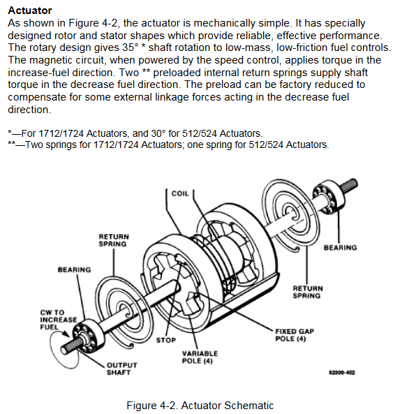
K-WANG


Woodward EPG electric speed regulator
Woodward EPG electric speed regulator
Overview
This manual covers models 512/524 and 1712/1724 of Woodward EPG (Electrically Powered Governor) electric governors, including synchronous models, covering installation, operation, calibration, troubleshooting, and other content. It is suitable for speed control of diesel, gas, and gasoline engines as well as gas turbines.
General information
Application scenario: Used to control the speed of diesel, gas, gasoline engines and gas turbines, suitable for prime movers of mechanical loads and generator loads. Parallel generator sets require additional equipment and Woodward generator load sensors.
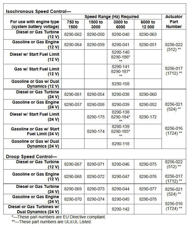
Model selection: 512/1712 models are used for 12V systems, and 524/1724 models are used for 24V systems. The speed controller has four frequency ranges for magnetic and electric sensors, suitable for different engine types. The actuator has a dual end output shaft that can rotate clockwise or counterclockwise to increase fuel consumption. You can also choose to activate functions such as fuel limit and dual dynamic characteristics, and select compatible speed controllers and actuators according to the model selection table.
Attachment: Includes generator load sensor (for parallel generator applications), ramp generator (for slowing down acceleration and deceleration), external capacitor (providing exponential ramp), etc.
Reference materials: Relevant publications can be obtained from authorized Woodward distributors or AISF, and can also be viewed on the Woodward website.
Installation, inspection, and calibration
Installation of speed controller: The working temperature range is -40 to+75 ° C (-40 to+167 ° F), and it should be installed in a location with adjustment and wiring space, avoiding exposure to radiant heat sources, close to actuators and batteries to meet wire length requirements, and ensuring good ventilation.
Installation of actuator and linkage device: The operating temperature range of the actuator is -40 to+93 ° C (-40 to+200 ° F), avoiding exposure to excessive heat sources. Suitable linkage devices need to be selected to match the rotation direction of the actuator and fuel control, ensuring that the linkage device moves flexibly, without friction or clearance. The actuator includes a reset spring, which does not require additional addition.
Installation of magneto electric sensor: Installed through the shell or rigid bracket, ensure that the detected gear is made of magnetic material, and the gap between the sensor and the outer diameter of the gear is about 1.0 millimeter (0.04 inch) at the closest point. The gap can be set in a specific way and the anti loosening nut can be tightened.
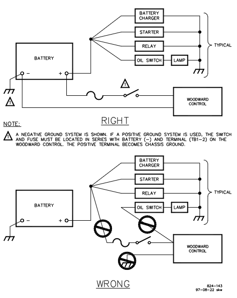
Wiring instructions: Use a specific wiring diagram for wiring, and use insulated terminals for all connections. The wiring to the actuator and battery should be as short as possible, and different models have different maximum wiring lengths. Fuses and switches or circuit breakers should be located in non grounded battery leads, and the connection between the battery and the speed controller terminal should come directly from the terminal, without passing through the distribution point. Attention should also be paid to the shielding layer connection and the installation of varistors required by EMC.
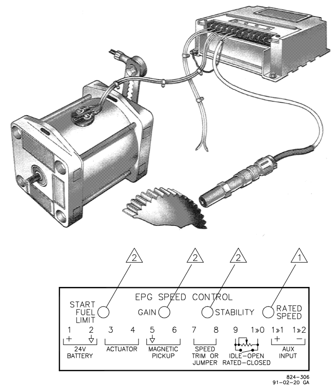
Installation inspection: including checking electrical connections, installation of magneto electric sensors, fastening of actuators and linkage devices, testing battery voltage, terminal voltage, preset rated speed and idle speed, adjusting gain and stability, setting starting fuel limits, etc. There are additional inspection steps for different application scenarios (such as applications with 2500 ramp generators and parallel generators).
Operate
The governor needs to be powered on at startup and powered off at shutdown (if the fuel control is in the minimum fuel position, power off will cause shutdown). The application of parallel generators requires synchronous and parallel operation. In droop mode, parallel operation requires adjusting the speed and fine tuning potentiometer to set the power generation. The EPG design is suitable for unmanned operation, and the idle rated switch can be controlled by multiple devices. When using the Woodward SPM synchronizer for parallel generator applications, equivalent automation operation can be achieved. The ramp generator can be used to provide adjustable speed change time between rated and idle.
Describe
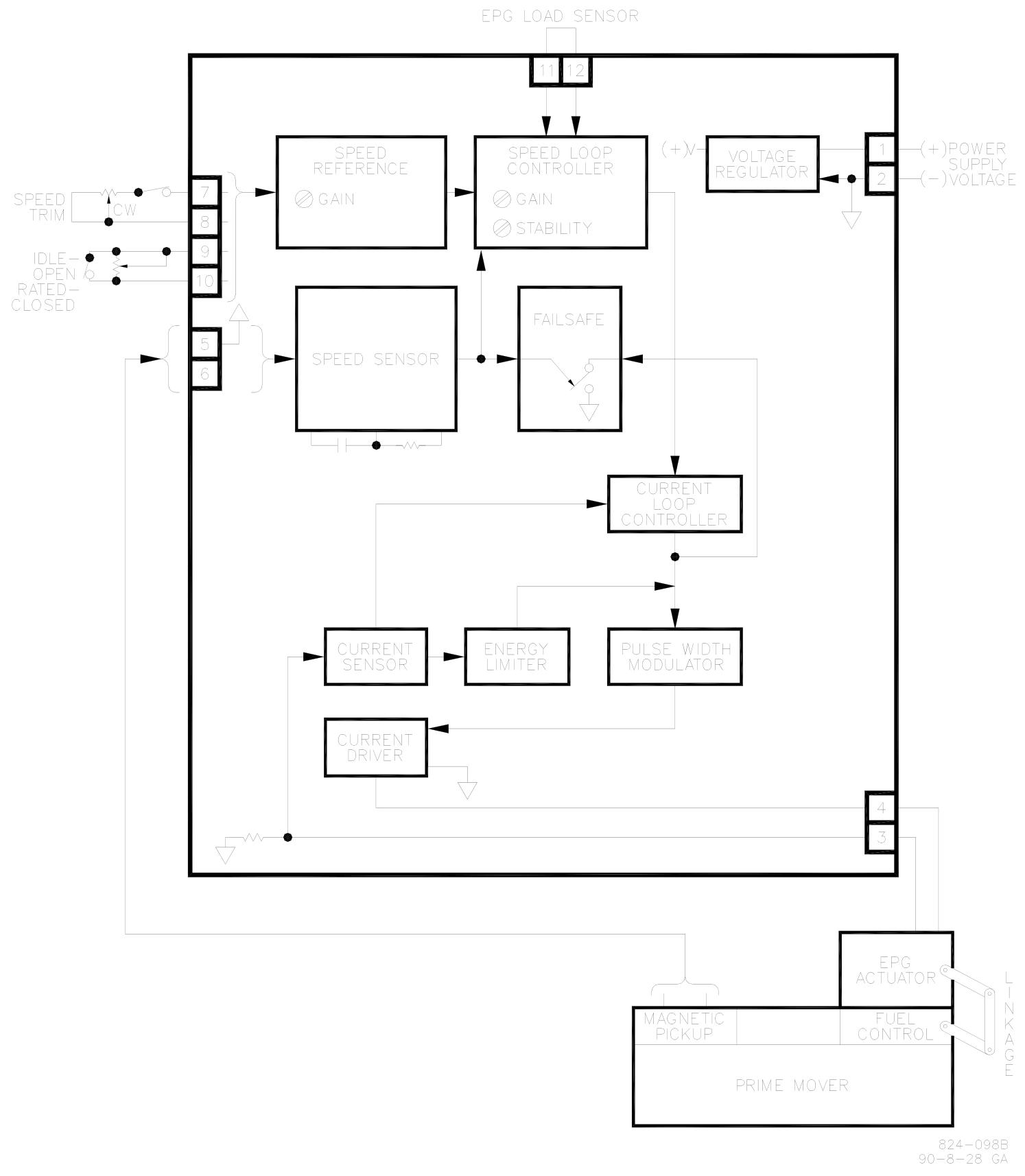
Speed control application: The basic speed control components include magneto electric sensors, speed controllers, and actuators, with two control loops: speed loop and current loop. The speed loop controller compares the expected speed with the actual speed, calculates the error signal, and adjusts the gain and stability to customize the governor response; The current loop ensures the correct driving of the actuator, including relevant circuits and protection mechanisms.
Executor: The mechanical structure is simple, with specially designed rotors and stators. The rotating design enables low-quality, low friction fuel control to achieve a certain angle of shaft rotation. When the magnetic circuit is energized, it provides torque in the direction of fuel increase, and the internal reset spring provides shaft torque in the direction of fuel decrease.
Application of using a ramp generator: slows down the speed change between idle and rated speed, without affecting steady-state speed, and controls the rate of change through acceleration and deceleration potentiometers.
Parallel generator application: Load sensors are used for synchronous or droop parallel connection. When isolating the bus, synchronous load distribution is usually selected. When parallel connected with infinite bus or incompatible electric speed controllers, droop operation is required.
Troubleshooting process
When there is a problem with the operation of the prime mover, it is necessary to first determine whether the fault is caused by the governor. The following methods can be used to troubleshoot:
Component replacement: Replace suspected faulty components with known normal ones.
System simplification: Gradually remove optional components and observe the performance changes after each removal.
Component testing: Test the output of suspected faulty components according to the manufacturer's instructions or known input and operating conditions.
When testing EPG, you can refer to the installation inspection steps in Chapter 2, where using a signal generator with isolated output for rated speed preset is the best way to test EPG speed control capability. If it involves the application of parallel generators, it is also necessary to refer to the inspection content of load sensors in the 82313 manual mentioned in Chapter 2.
Other inspection items
Unstable speed or power output
If the prime mover remains stable at certain speeds or power outputs but oscillates in other situations, it may be due to incompatibility between the linkage device and fuel control. Please refer to the "Linkage Device Compatibility" section under "Installation of actuators and linkage devices" in Chapter 2.
If there is a low-frequency oscillation of about 1Hz in the prime mover and the gain and stability adjustments in Chapter 2 are correct, it may be due to friction in the linkage device. It is necessary to disconnect the actuator from the fuel control, manually operate the fuel control linkage device, check whether it moves flexibly without friction or clearance, and lubricate or replace components if necessary.
Unstable load distribution
Verify if the current transformers (CTs) and voltage transformers (PTs) of the load sensor are wired correctly.
Check if the droop or cross current compensation settings of the voltage regulator are correct, and if there are intermittent faults or other issues with the voltage regulator.
If the problem persists, the load gain can be appropriately reduced and the load gain potentiometers of all other load sensors in the system can be set to have the same load signal at full load. In extreme cases, the load signal may need to be reduced to 3 volts. In this case, authorized dealers or Woodward can be consulted.
Fuse or circuit breaker issues
If the fuse or circuit breaker disconnects after the prime mover is running, it may be due to high voltage spikes generated by the battery or battery charger. It is necessary to separately wire from the speed controller to the battery terminal as shown at the top of Figure 2-6.
If the fuse or circuit breaker is disconnected during initial startup, it may be a battery connection error. It is necessary to verify whether the battery connection is correct, remove the wires from terminals 1 to 4, and check whether each wire is short circuited to ground.
Differences in performance between hot and cold states
If the prime mover oscillates in the cold state and stabilizes in the hot state, the gain potentiometer can be slightly rotated counterclockwise. If stability needs to be maintained, the stability potentiometer can be slightly rotated clockwise.
- YOKOGAWA
- Reliance
- ADVANCED
- SEW
- ProSoft
- WATLOW
- Kongsberg
- FANUC
- VSD
- DCS
- PLC
- man-machine
- Covid-19
- Energy and Gender
- Energy Access
- Renewable Integration
- Energy Subsidies
- Energy and Water
- Net zero emission
- Energy Security
- Critical Minerals
- A-B
- petroleum
- Mine scale
- Sewage treatment
- cement
- architecture
- Industrial information
- New energy
- Automobile market
- electricity
- Construction site
- HIMA
- ABB
- Rockwell
- Schneider Modicon
- Siemens
- xYCOM
- Yaskawa
- Woodward
- BOSCH Rexroth
- MOOG
- General Electric
- American NI
- Rolls-Royce
- CTI
- Honeywell
- EMERSON
- MAN
- GE
- TRICONEX
- Control Wave
- ALSTOM
- AMAT
- STUDER
- KONGSBERG
- MOTOROLA
- DANAHER MOTION
- Bentley
- Galil
- EATON
- MOLEX
- Triconex
- DEIF
- B&W
- ZYGO
- Aerotech
- DANFOSS
- KOLLMORGEN
- Beijer
- Endress+Hauser
- schneider
- Foxboro
- KB
- REXROTH
- YAMAHA
- Johnson
- Westinghouse
- WAGO
- TOSHIBA
- TEKTRONIX
- BENDER
- BMCM
- SMC
- HITACHI
- HIRSCHMANN
- XP POWER
- Baldor
- Meggitt
- SHINKAWA
- Other Brands
- UniOP
- KUKA
- IBA
- Beckhoff
-
ADLINK PCI-7433 - switch value acquisition card Isolated Digital Input Card
-
ADLINK PCI-9112 - 51-12252-0D20 Multi-Function Data Acquisition Card
-
ADLINK NUPRO-A301 REV:1.4 - industrial control motherboard PICMG Full-Size SBC
-
ADLINK 51-18502-0A10 - Frame Grabber Image Acquisition Interface Card
-
ADLINK PCI-7296 - 51-12009-0A50 PCB-I-E-925=6DX1 96-CH Parallel Digital I/O Board
-
ADLINK PCI-8132 GP A2 - Motion Control Card 2-Axis Servo & Stepper Controller
-
ADLINK PCI-7442 - switch quantity card data acquisition card 64-CH Isolated Card
-
ADLINK HPX-13S4 - baseboard PICMG 1.3 Passive Backplane Chassis Baseplate
-
ADLINK NuPRO-590 / NTC-567-ZM-F36 - Single Board Computer PCB-I-E-1853=9L21 Half-Size SBC
-
ADLINK PCIe-8332 - 16-axis plate Motion Control Hardware Card
-
ADLINK NuPRO-775 REV.B1 - motherboard Pentium 4 Full-Size PICMG SBC
-
ADLINK PXI-3920 - Embedded Controller 3U PXI cPCI System Intelligence Board
-
ADLINK PCI-8134 - driver card motion control card 4-Axis Controller Board
-
ADLINK HSL-DI32-M-N-011 / HSL-TB32-M-DIN - Digital Input & Base Module PLC Distributed I/O System
-
ADLINK PCI-6216V-206 / PCI-208V 009 - 16 CH 16bit analog output card
-
ADLINK NuPro-E330 - 51-41805-0A20 PCB Single Board Computer Host Board
-
ADLINK PCI-1622C - Card 8-Port RS-232/422/485 PCI Serial Communication Board
-
ADLINK PCIe-7432 - 51-18402-0A10 Carte PCIe Avec Plage D'Entrée Élevée Isolated DIO Card
-
ADLINK PCI-7250 - PCI Acquisition Card 8-CH Relay Output Isolated DI Card
-
ADLINK PCI-7230 - 32-CH Isolated Digital I/O Card
-
ADLINK PCI-8164 - PCB 4-Axis Motion Controller Card
-
ADLINK PCI-7854 - Collection card High-Speed Link Distributed Motion Controller
-
ADLINK NuPRO-935A/LV - industrial control computer motherboard Full-Size PICMG SBC
-
ADLINK IMB-M40H - motherboard IH61-AA4 1155 LGA1155 Micro-ATX Mainboard
-
ADLINK PCI-7248 - Linhua 51-12006-0A40 48-CH Parallel Digital I/O Card
-
ADLINK HPCI-14S12U - Linhua industrial computer baseboard Passive Backplane
-
ADLINK PCI-8132 Rev.A2 - 2-Axis Servo & Stepper Motion Controller Card
-
ADLINK ACL-8111 - ISA card Multi-Function DAQ Card
-
ADLINK ACL-8111 - ISA card Multi-Function Data Acquisition Board
-
ADLINK PCI-7200 REV.A3 - Digital I/O card 12MB/s High-Speed Parallel Digital I/O
-
ADLINK PCI-7296 REV.A3 - 96-CH High-Density Opto-Isolated DIO Card
-
ADLINK PCI-7434 - 64-CH Isolated Digital Output Card
-
ADLINK M-342 - atx motherboard Industrial PC Mainboard
-
ADLINK NuPRO-935ADV (A) 1.9 - CPU Board Intel Core 2 Quad CPU Q9500 2.83GHz PICMG Board
-
ADLINK NUPRO-935A/DV - motherboard dual network port 51-41802-0A10 CPU Board
-
ADLINK PCI-RTV24 - image capture card Analog Video Frame Grabber Board
-
ADLINK HPX-13S4 - device baseboard PICMG 1.3 Passive Backplane Chassis Baseplate
-
ADLINK PCI-8134A - control card 4-Axis Motion Controller Card
-
ADLINK ACL-7130 REV. B2 - industrial control capture card Isolated Digital I/O Board
-
ADLINK EBP-13E2 - Industrial Backplane Board Passive Backplane Baseboard
-
ADLINK NuPRO-935ADV (A) 1.9 - CPU Board Intel Core 2 Quad CPU Q9500 2.83GHz PICMG SBC
-
ADLINK PCI-8134A - motion control card 4-Axis Pulse-Train Controller Card
-
ADLINK PCI-9112 REV A.1 - Multi Function DA&C Board Data Acquisition Card
-
ADLINK 51-12001-0C20 - Circuit Board Multi-Function Data Acquisition Hardware
-
ADLINK PCI-7300A - 80-CH High-Speed Digital I/O Card
-
ADLINK PCI-7230 - 16-CH Isolated Digital Input Output Card
-
ADLINK DIN-814-GP - motion control module Interface Terminal Block
-
ADLINK NUPRO-A40H - 51-41807-1A20 Industrial Control Motherboard LGA1155
-
ADLINK PCI-7433 rev A2 - Isolated Digital Input Card
-
ADLINK NuPRO-780 - Pentium III 800 512 MB SBC NuPRO780 51-41309-0B2 Single Board Computer
-
ADLINK PCI-7853 / PCI-7854 - Acquisition card High-Speed Link Control Card
-
ADLINK NUPRO-852 / NUPRO-852LV - Industrial motherboard Full-Size PICMG CPU Board
-
ADLINK NuPRO-842LV/P - 51-41360-0B30 Industrial Motherboard Half-Size PICMG SBC
-
ADLINK PCI-FIW64 - 4/2 Channel IEEE1394B Image Capture Card Frame Grabber
-
ADLINK PCI-7851 Rev A1.1 - HSL system card High-Speed Link Master Controller
-
ADLINK PCI-7230 - 51-12003-0A50 card 32-CH Isolated Digital I/O Card
-
ADLINK NuPRO-841REV:1.0 - Industrial CPU Board Mainboard
-
ADLINK NuPRO-841 REV:1.0 - motherboard Industrial Control PC Mainboard
-
ADLINK PCI-8256 - 8-Axis Advanced Motion Control PCI Board
-
ADLINK PCI-6S / PCI6S - Backplane 6-Slot Passive Backplane Board
-
ADLINK PCI-7234 REV B3 - 32-CH Isolated Digital Output PCI Card
-
ADLINK PCI-8213 - HannStar MV-4 51-45003-0b4 Board
-
ADLINK PCI-7233 - 51-12004-0a20 board PCI7233 32-CH Isolated Digital Input Card
-
ADLINK PCI-7851 - 006 51-24003-0B20 High-Speed Link Master Motion Control Card
-
ADLINK PCI-7432 - 64-CH Isolated Digital I/O PCI Cards
-
ADLINK LPCI-3488 - Card Low Profile IEEE-488 GPIB Interface Card
-
ADLINK HPCI14S REV.B1 - industrial control computer base plate Passive Backplane
-
ADLINK NEON-1020 - Industrial camera Smart Camera Vision System
-
ADLINK PCI-7432 - Isolated Digital I/O PCI Card 64-CH
-
ADLINK Pcm-7250+ - 8-Ch Relay Outputs & 8-Ch Isolated DI Module PC/104
-
ADLINK CPCI-7841 - DUAL-PORT ISOLATED CAN INTERFACE CARD CompactPCI
-
ADLINK PCI-3488 / PCI-GPIB - PCI IEEE-488 GPIB Interface Card
-
ADLINK PCI-1711U - Card Multi-Function Data Acquisition Board
-
ADLINK NUPRO-A301 - REV:1.1 1.2 1.4 PICMG Full-Size Single Board Computer
-
Adlink DIN-50S-01 - PLOTECH 51-14024-0A40 50-pin Wiring Terminal Board
-
Chroma 52962 / 58183 - PXI Optical Spectrometer carrier adapter Card
-
ADLINK PCI-6208V - PCI DATA ACQUISITION & RECORDING CARD 8-CH Analog Output
-
ADLINK HSL-DI32-DB-N - Industrial Control Board Distributed Digital Input Module
-
ADLINK HSL-AO4-U - 4-CH HIGH SPEED LINK ANALOG OUTPUT MODULE Distributed I/O
-
ADLINK PCI-7396 - 0050 GP 51-12012-0B20 96-CH High-Speed Digital I/O Card
-
ADLINK NUPRO-935A/DV - 51-41802-0A10 motherboard Industrial CPU Single Board Computer
-
ADLINK PCI-9111 DG - Industrial Acquisition Card Multi-Function DAQ Card
-
ADLINK NuPRO-E315 - industrial computer motherboard Intel Atom SHB SBC
-
ADLINK NUPRO-406 REV:B1 - Industrial Control Motherboard Full-Size PICMG CPU Board
-
ADLINK NuPRO-E330 - motherboard Industrial Control System Host Board PICMG 1.3
-
ADLINK ACL-6128A 103 - 51-11002-1A4 2-CH Isolated Analog Output Card
-
XTRAMUS cPS-H325/AC - POWER SUPPLY NUSTREAMS 600 NETWORK TESTING EQUIPMENT Power Module
-
ADLINK DIN-814P-A4 - 51-14056-0A10 Terminal Block Motion Control Breakout Board
-
ADLINK TB-24P/24-01 - 24-Channel Card Terminal Breakout Board
-
ADLINK PCI-7251 - 51-12008-0A30 PCI7251 8-CH Relay Output Isolated Digital Input Card
-
Basler Electric DECS-250-CN1SN1N Automatic Voltage Regulator for Generator Excitation Control
-
ADLINK CPCI-6860A - 51-31310-OB10 industrial motherboard CompactPCI SBC
-
ADLINK AmITX-SL-G-H110 - 51-7A104-0A30 Mini-ITX Industrial Motherboard
-
ADLINK PXI-2005-003 - CPCI Industrial PC Data Acquisition Card Multi-Function DAQ
-
ADLINK DININ-814M - 51-14032-0A3D SCSI-100P cable connection Interface Terminal Board
-
ADLINK CPCI-3920NA/C2D15/M1G - 3U CompactPCI Intel Core 2 Duo Single Board Computer
-
ADLINK PCIE-8560 - 51-18014-0A20 Communication Card High Speed DAQ
-
ADLINK PCI-C154+ - Motion Control Card 4-axis Motion Controller Board
-
ADLINK PCI-RTV24 - image capture card Analog Video Frame Grabber
-
ADLINK NuPRO-842LV/P - 51-41360-0B30 Industrial Motherboard CPU Board
-
ADLINK cBP-3208/3208R - CPCI Board 3U 8-Slot CompactPCI Backplane
-
ADLINK PCI-8164 - 4-Axis Motion Controller PCI Card 51-12406-0A40
-
ADLINK PCIe-GIE64+ - 4-CH GigE Vision PoE+ Frame Grabber Video Capture Card
-
ADLINK CPCI-6860 / 6860A - CompactPCI Dual Xeon Single Board Computer
-
ADLINK IEC-915GV - REV 1.1 Industrial motherboard CPU Board
-
ADLINK ND-6520 - Technology RS-232 to RS-422RS-485 Converter NuDAM Module
-
ADLINK RTV-24 / PCI-MP4S - 51-12519-1C30 4-Channel Real Time Video Capture Board
-
ADLINK cPCI-6910 / cPCI-6910AM/M1G - cPCI-6910AM/DXL16/M1G/S80G(G)-3120 BOARD CompactPCI SBC
-
ADLINK NUPRO-A40H - Linghua 51-41807-1A30 Industrial Control Computer Motherboard
-
ADLINK USB-3488A - USB to GPIB INTERFACE USB-3488A(G) Controller Module
-
ADLINK PCI-8134A - motion control card 4-Axis Controller Card
-
ADLINK PCI-7432 - Board 32-Channel input / 32-output Isolated Digital I/O PCI Card
-
ADLINK PCI-8134A - 51-12421-0A10 motion controller card tested
-
ADLINK LPCIe-7230 - 32 CH Isolated Input/output Card 2 Interrupts Low Profile PCIe
-
ADLINK NuPRO-E340 - industrial computer motherboard 51-47807-0A30 PICMG 1.3 SHB
-
ADLINK PCI-7434 - High-speed Digital Acquisition Card 64-CH Isolated DO Card
-
ADLINK NuPRO-E330 - 51-41805-0A20 Indsutrial Board SHB Single Board Computer
-
ADLINK PCI-7248 - OPTO-22 48 CHANNEL DIO DIGITAL TTL/DTL I/O 51-12006-0A40 GP
-
ADLINK PCI-8134 - Motion control card 4-Axis Controller Card
-
ADLINK AMP-208C - Movimiento Control Tarjeta 51-12420-1A20 W/Expansión & Breakout
-
ADLINK PCI-8164 - 51-12406-0A40 PCB Board 4-Axis Motion Controller Card
-
ADLINK DIN-68Y-SGII / DIN-68M-J3A - Terminal Board Connector Interface Block
-
ADLINK PCIe-7432 - Technology 51-18402-0A10 PCIe Card With High Input Range
-
ADLINK PCI-8144 / PCI-8144N - Motion control card 4-Axis Stepper Controller Card
-
ADLINK HSL-HUB3/REPEATER - HIGH SPEED LINK EXTENSION MODULES Distributed Hub Module
-
ADLINK ND-6017 - Data Logging + Acquisition 8CH A/D input Mod NuDAM Module
-
ADLINK LPCIe-7250 - data acquisition card Low Profile 8-CH Relay Output Card
-
ADLINK PCI-7432 - I/O card 64-CH Isolated Digital Input Output PCI Card

K-JIANG

Add: Jimei North Road, Jimei District, Xiamen, Fujian, China
Tell:+86-15305925923