
K-WANG


WAGO I/O System 750/753 Series Distributed Automation System
Applicable scenarios: Indoor dry environments in the field of industrial automation, suitable for ordinary industrial areas, and certified for special scenarios such as marine, nearshore, explosion-proof (Ex i), functional safety, etc.
Installation requirements: As an open device, it needs to be installed in an additional enclosure and operated by professional electrical personnel according to standards such as EN 50110-1/-2 and IEC 60364.
WAGO I/O System 750/753 Series Distributed Automation System
Core positioning and purpose of the system
Core function: Receive digital/analog signals from sensors, control actuators, communicate with higher-level controllers through fieldbus interfaces, and support signal preprocessing.
Applicable scenarios: Indoor dry environments in the field of industrial automation, suitable for ordinary industrial areas, and certified for special scenarios such as marine, nearshore, explosion-proof (Ex i), functional safety, etc.
Installation requirements: As an open device, it needs to be installed in an additional enclosure and operated by professional electrical personnel according to standards such as EN 50110-1/-2 and IEC 60364.
System hardware structure and characteristics
1. Classification and functions of core components
Specific classification of component types and key characteristics
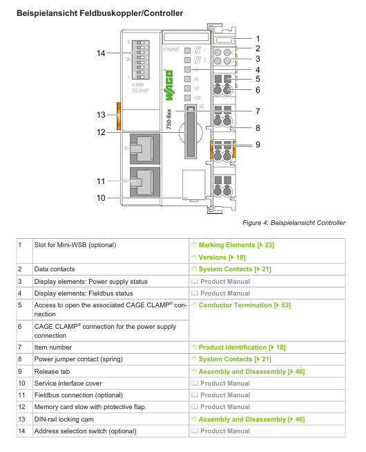
Head Stations' fieldbus couplers, controllers, and PFCs provide fieldbus interfaces (such as PROFINET and ETHERNET) to manage I/O module communication and power supply, with reset keys, status indicator lights, and service interfaces
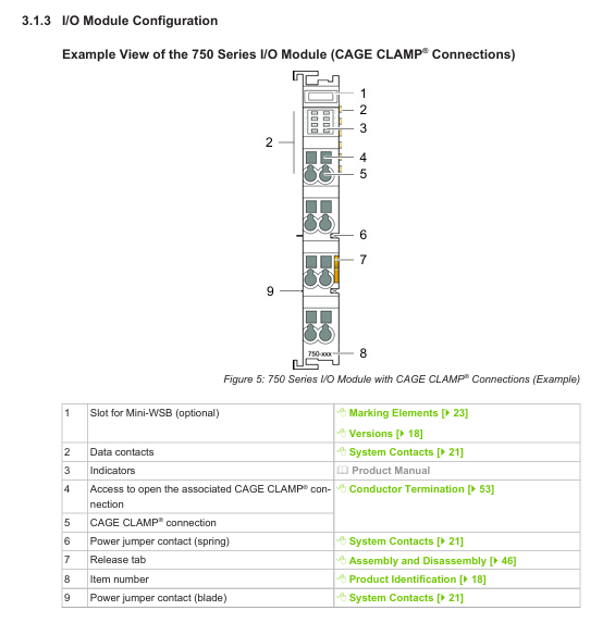
I/O module analog input/output module supports voltage and current signal acquisition and output, distinguished by color coding (green=analog input, blue=analog output)
The digital input/output module is adapted to switch signals, with color codes of yellow (input) and red (output)
Functional/technical modules include relay module, communication module, filtering module, and transparent shell identification
The power/segment module provides system/on-site power supply, supports potential partitioning, and can interrupt or switch power supply links
The auxiliary component end module is used for node end sealing to ensure mechanical stability
Distance module (750-616) is used to increase creepage distance in explosion-proof scenarios, with a width of 12mm
2. Module physics and connection characteristics
Appearance and coding:
Types of shell color differentiation: light gray (standard module), blue (Ex i explosion-proof), signal yellow (functional safety), dark gray (750 XTR).
Marking information: including product model, wire cross-section, production data, DataMatrix code, CE/UL/Ex certification identification, etc. The head station serial number is marked on the service interface cover plate.
Connection technology:
CAGE CLAMP ®: It needs to be opened with operating tools and supports solid, multi strand, and thin multi strand conductors (0.08-4mm ²).
Push-in CAGE CLAMP ®: Tool free direct insertion (multi strand/thin multi strand conductors with cold pressed ends, solid conductors), other conductors require tool assistance.
Mechanical parameters:
Module width: 12mm, 24mm, 48mm, maximum node length (from head station to end module) ≤ 768mm.
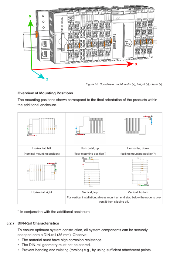
Installation adaptation: 35mm DIN rail, fixed by locking cam, supports horizontal (left/right/up/down) and vertical (up/down) installation posture.
3. Electrical structure and power supply
Potential level:
System level: including system power supply (24VDC), local bus signals, and electrical isolation from other levels.
On site level: including on-site power supply (24VDC/230VAC, etc.), I/O signals, and can be divided into multiple potential zones.
Fieldbus level: independent of the first two, voltage/current depends on the fieldbus standard.
Power supply requirements:
System power supply: SELV/PELV power supply is required, and the total current of a single node should not exceed the rated value of the module. It is recommended to use the same voltage source for power supply.
On site power supply: configured according to the load, supporting different voltages in multiple areas (such as 24VDC, 230VAC), and requiring overcurrent protection (integrated fuse power module or external fuse).
Buffer requirements: When meeting the IEC 61131-2 standard, an external buffer module (such as UPS, capacitor buffer) is required.
System Planning and Installation Specification
1. Core requirements for node planning
Node composition: It should include at least one head station, one power module, one I/O module, and one end module, and support up to 250 addressable I/O modules.
Security planning:
In hazardous voltage scenarios, DIN rails must be grounded (PE) to ensure electrical connection with the enclosure/frame.
Control lines, signal lines, and power lines need to be spatially separated to avoid electromagnetic interference.
Data security: control the isolation of the network from the Internet/office network, close useless ports, change passwords regularly, and adopt the "defense in depth" mechanism.
Installation gap:
Both sides of the node should be ≥ 20mm, and the top and bottom should be ≥ 35mm (if the top is a heating component, it should be ≥ 65mm), to avoid blocking heat dissipation.
2. Installation and disassembly steps
Installation process:
Head station installation: The buckle is fixed on the DIN rail, and the locking cam is rotated with a tool to engage.
I/O module installation: Assemble from left to right in sequence, press until the buckle is locked. The 753 series requires fixing the module before connecting the wiring interface.
Encoding configuration: The 753 series module prevents accidental insertion by encoding the key (753-150), with 2 keys supporting 16 encoding combinations.
Dismantling process:
Power outage confirmation: Disconnect the system from the on-site power supply and verify that there is no voltage before operation.
Head station disassembly: Unlock the locking cam with the tool, pull the release buckle to detach from the guide rail.
I/O module disassembly: 750 series, directly pull the orange release buckle; The 753 series first separates the wiring interface (pull the locking latch), and then pull the release buckle.
3. Wiring operation specifications
Conductor requirements:
Supports copper and aluminum conductors (aluminum conductors need to be cleaned and coated with "Alu Plus" contact paste), with only one conductor connected to a single clamping unit.
The cross-sectional area of the wire needs to match the current load, and larger cross-sectional conductors should be selected in high current scenarios to reduce temperature rise.
Wiring steps:
CAGE CLAMP ®: Insert the tool into the rectangular opening to open the fixture → Insert the conductor → Pull out the tool lock.
Push-in CAGE CLAMP ®: Direct insertion adapter conductor; Non compatible conductors require tools to be tilted and inserted into the opening after opening the fixture.
Special scenario application configuration
1. Marine and nearshore scenarios (DNV certified)
Classification requirements:
Class A: Suitable for non bridge and non outdoor deck areas; Class B: Suitable for the entire area (including the bridge and outdoor deck).
Power supply configuration:
A high isolation (HI) filtering module is required for 24VDC power supply: the 750-626 series is used for system power supply, and the 750-624 series is used for on-site power supply.
Isolation monitoring scenarios require the use of HI version filtering modules (such as 750-624/020-000, 750-626/020-000).
Exception: Non 24VDC on-site power supply does not require additional filtering modules.
2. Explosion proof (Ex i) scenarios
Power supply requirements:
Only use Ex i dedicated bus power supply module (750-606 with diagnosis, 750-625/000-001 without diagnosis).
Distance requirement:
The Ex i power supply module needs to be connected in series in front of the Ex i module area, and four distance modules (750-616) need to be connected behind the area; If the subsequent module is the bus extension end module (750-627), only one distance module is required; If it is a regular end module (750-600), no distance module is required.
Operation restrictions: It is prohibited to plug or unplug components, connect wires, operate switches, or replace fuses in explosive environments.
3. Functional safety scenarios
Power supply protection:
The system and on-site power supply (24VDC) require the configuration of filtering modules (750-626 series for the system and 750-624 series for the site) to meet the surge protection requirements of EN 61326-3-1.
Module requirements: Use I/O modules with Functional Safety Identification (FS) and configure redundancy or isolation measures according to safety levels.
4. UL certification scenario requirements
Ordinary area:
The 24VDC system requires an external slow melting fuse (maximum 2A, minimum 30VDC) for power supply.
24VDC on-site power supply requires external slow melting fuses (maximum 10A, minimum 30VDC); ≤ 250VAC/DC on-site power supply fuse, maximum 10A.
Dangerous Area (Class I, Division 2):
It needs to be installed in the shell unlocked by the tool, and can only be operated after power off or confirming that there is no risk of explosion in the area.
Specific modules (such as 750-439, 750-538) are only allowed to be used in conjunction with Ex i power supply modules (750-606/750-625).
Safety and compliance requirements
1. General safety regulations
Personnel qualifications: Installation, operation, and maintenance must be carried out by professional electrical personnel who comply with EN 50110-1/-2 and IEC 60364 standards.
Electrical safety:
Disconnect all power supplies before operation and verify that there is no voltage; SELV/PELV circuits need to be safely isolated from hazardous voltage circuits.
To avoid electrostatic discharge (ESD), take protective measures according to DIN EN 61340-5-1/-3 (such as anti-static wristbands).
Mechanical and thermal safety:
Do not open the product casing and avoid touching live contacts; The shell may generate heat and needs to be cooled before touching in high temperature environments.
Do not use cleaning agents that contain penetrant/insulating properties (such as silicone, glycerin). Isopropanol can be used for cleaning.
2. Certification and Compliance
International certifications: including CSA, KEMA/KEUR, ABS (Classification Society), UL, ATEX, EAC, CCC, RCM and other certifications.
Following standards: EN 60947, UL 1059, IEC 61010-1, WEEE (Waste Disposal), etc.
Intellectual Property: The content of the document is protected by copyright and may not be copied or distributed without written permission from WAGO; Third party trademarks and patents belong to the corresponding party.
3. Disposal and Recycling
Disposal requirements: Classify and recycle electrical and electronic waste according to local regulations, and do not mix it with household waste.
Preprocessing: Remove memory cards and batteries (such as lithium batteries and lead-acid batteries), clear stored data, and operate with protective equipment.
Packaging recycling: B2B transportation packaging can be recycled for free through the Interseroh system.
Supporting tools and accessories
1. Configuration and debugging tools
COCKPIT: integrates hardware configuration, programming, simulation, visualization, and debugging functions, supporting fully automated processes.
WAGO Smart Designer: 3D configuration tool that can design node structures and calculate power requirements.
WAGO-I/O-CHECK: Used for testing 750/753/XTR series nodes, supporting input/output control and status monitoring.
2. Essential Attachment List
Attachment Type Model Example Function
DIN rail 210-1xx series steel/copper material, 35mm specification, galvanized/chrome plated treatment
Operating tool 210-722 insulated handle, compatible with CAGE CLAMP ® wiring
Test probes 735-500, 859-500 1mm diameter, supporting 30VAC/60VDC, CAT0 level
Code key 753-150 753 series module anti misplacement, providing 16 different codes
Marking part 2009-145 Mini WSB Inline marking, roll up 1500 pieces, stretchable 5-5.2mm
End block 249-1xx series screw free end block, compatible with 35mm DIN rail
Shielding connection system 790 series enhances cable shielding grounding effect and reduces electromagnetic interference
Buffer module 787 series capacitor buffer ensures power supply stability
- YOKOGAWA
- Reliance
- ADVANCED
- SEW
- ProSoft
- WATLOW
- Kongsberg
- FANUC
- VSD
- DCS
- PLC
- man-machine
- Covid-19
- Energy and Gender
- Energy Access
- Renewable Integration
- Energy Subsidies
- Energy and Water
- Net zero emission
- Energy Security
- Critical Minerals
- A-B
- petroleum
- Mine scale
- Sewage treatment
- cement
- architecture
- Industrial information
- New energy
- Automobile market
- electricity
- Construction site
- HIMA
- ABB
- Rockwell
- Schneider Modicon
- Siemens
- xYCOM
- Yaskawa
- Woodward
- BOSCH Rexroth
- MOOG
- General Electric
- American NI
- Rolls-Royce
- CTI
- Honeywell
- EMERSON
- MAN
- GE
- TRICONEX
- Control Wave
- ALSTOM
- AMAT
- STUDER
- KONGSBERG
- MOTOROLA
- DANAHER MOTION
- Bentley
- Galil
- EATON
- MOLEX
- Triconex
- DEIF
- B&W
- ZYGO
- Aerotech
- DANFOSS
- KOLLMORGEN
- Beijer
- Endress+Hauser
- schneider
- Foxboro
- KB
- REXROTH
- YAMAHA
- Johnson
- Westinghouse
- WAGO
- TOSHIBA
- TEKTRONIX
- BENDER
- BMCM
- SMC
- HITACHI
- HIRSCHMANN
- XP POWER
- Baldor
- Meggitt
- SHINKAWA
- Other Brands
- UniOP
- KUKA
- IBA
- Beckhoff
-
ADLINK CPCI-6860A - 51-31310-OB10 industrial motherboard CompactPCI SBC
-
ADLINK AmITX-SL-G-H110 - 51-7A104-0A30 Mini-ITX Industrial Motherboard
-
ADLINK PXI-2005-003 - CPCI Industrial PC Data Acquisition Card Multi-Function DAQ
-
ADLINK DININ-814M - 51-14032-0A3D SCSI-100P cable connection Interface Terminal Board
-
ADLINK CPCI-3920NA/C2D15/M1G - 3U CompactPCI Intel Core 2 Duo Single Board Computer
-
ADLINK PCIE-8560 - 51-18014-0A20 Communication Card High Speed DAQ
-
ADLINK PCI-C154+ - Motion Control Card 4-axis Motion Controller Board
-
ADLINK PCI-RTV24 - image capture card Analog Video Frame Grabber
-
ADLINK NuPRO-842LV/P - 51-41360-0B30 Industrial Motherboard CPU Board
-
ADLINK cBP-3208/3208R - CPCI Board 3U 8-Slot CompactPCI Backplane
-
ADLINK PCI-8164 - 4-Axis Motion Controller PCI Card 51-12406-0A40
-
ADLINK PCIe-GIE64+ - 4-CH GigE Vision PoE+ Frame Grabber Video Capture Card
-
ADLINK CPCI-6860 / 6860A - CompactPCI Dual Xeon Single Board Computer
-
ADLINK IEC-915GV - REV 1.1 Industrial motherboard CPU Board
-
ADLINK ND-6520 - Technology RS-232 to RS-422RS-485 Converter NuDAM Module
-
ADLINK RTV-24 / PCI-MP4S - 51-12519-1C30 4-Channel Real Time Video Capture Board
-
ADLINK cPCI-6910 / cPCI-6910AM/M1G - cPCI-6910AM/DXL16/M1G/S80G(G)-3120 BOARD CompactPCI SBC
-
ADLINK NUPRO-A40H - Linghua 51-41807-1A30 Industrial Control Computer Motherboard
-
ADLINK USB-3488A - USB to GPIB INTERFACE USB-3488A(G) Controller Module
-
ADLINK PCI-8134A - motion control card 4-Axis Controller Card
-
ADLINK PCI-8134 - 51-12403-0B20 PCB Board Motion Controller Card
-
ADLINK LPCI-3488A - PCI Card 51-12801-0A30 Low Profile IEEE-488 GPIB Card
-
ADLINK NUPRO-900A - industrial computer motherboard Single Board Computer
-
ADLINK cPCI-6840V - industrial control motherboard CompactPCI SBC
-
ADLINK M-342 - industrial motherboard ATX Mainboard
-
ADLINK NUPRO-935A/LV - industrial control motherboard
-
ADLINK cPCI-3538 - CompactPCI Async Serial Communications Module
-
ADLINK PCI-1610 - Card 4-Port RS-232 PCI Serial Communication Card
-
ADLINK HSL-DI32-DB-N - Distributed I/O Module 32-CH Digital Input
-
ADLINK CPCI-6860A - motherboard E7501 CompactPCI Single Board Computer
-
ADLINK PCI-8134A - 4-Axis Motion Control Card PCB Board
-
ADLINK EURESYS LINK - grabbers Video Capture Card Frame Grabber
-
ADLINK NuPRO-965DV - motherboard Industrial Control Board
-
Thermo Fisher Scientific 80100-60500 - 80000-61010R 80000-21000R 80000-60457 Spectrum System Controller ADLINK Components
-
ADLINK PCI-7296 - IO card High Density 96-CH Opto-Isolated DIO Card
-
ADLINK MXC-6322D - Matrix Industrial Computer Fanless Embedded PC
-
ADLINK DIN-825-GP4 - connector board Terminal Block Interface
-
ADLINK AMP-208C - Motion Control Card DSP-based 8-axis
-
ADLINK PCIe-GIE72 - 51-18531-0A10 2-CH GigE Vision Frame Grabber PoE+ Card
-
ADLINK PXIS-3320 - PXI/PXIe Chassis 15-slot 6U PXI/CompactPCI SEM-I-1518=9N41
-
ADLINK MI-965 - Industrial CPU Motherboard
-
ADLINK M-302 - Industrial control motherboard
-
ADLINK PCI-6308V - 51-12202-0A50 Isolated Analog Output Card PCB-I-E-1813=ZA03
-
ADLINK NUPRO-935A - Industrial Mother Board CPU Board
-
ADLINK PCI-7434 - PLOTECH Digital Output Card PCB-I-E-1182=6EX2
-
ADLINK PCI-7432 - 64 Channel Isolated Digital I/O PCI CARD
-
ADLINK NUPRO-935A/DV - 51-41802-0A10 motherboard Industrial Control Board
-
ADLINK PCIe-GIE72 - 51-18531-0A10 2-CH GigE Vision Frame Grabber PoE+ Card
-
ADLINK HSL-DI16DO16-M-NN - HSL-DI16DO16-M-NN(G)-0280 Discrete I/O Module Distributed I/O
-
ADLINK cPCI-6760D / cPCI-6840V - cPCI Single Board Computer Industrial Motherboard
-
ADLINK NuPRO-A301 - Motherboard IPC Motherboard
-
ADLINK NuPRO-935A/LV - motherboard Industrial Control Board
-
ADLINK NUPRO-E320LV - motherboard Industrial Control Board
-
ADLINK NuPRO-E42 - Industrial Control Board Motherboard
-
ADLINK M-342 - ATX Motherboard Industrial PC Mainboard
-
ADLINK CPCI-6860 / 6860A - Industrial Control Motherboard CompactPCI SBC
-
ADLINK AmITX-SL-G-Q170/GEHC(EA)-021E - 51-7A104-0A20 Industrial Motherboard w/ DDR4
-
ADLINK NUPRO-852 / NUPRO-852LV - industrial control motherboard
-
ADLINK DAQ-2006-004 - Multi-Function DAQ Cards Data Acquisition
-
ADLINK PCIe-RTV24 - Frame Grabbers Video Capture Cards PCI-e x1 4-CH 120fps
-
ADLINK PCI-8134 - 51-12403-0B20 4-Axis Motion Controller Card
-
ADLINK PCI-8132 - 2-Axis Motion Controller Card
-
ADLINK cBP-6402 - Backplane Passive Backplane
-
ADLINK cPCI-6760D - cPCI Single Board Computer Industrial Control Motherboard
-
ADLINK DIN-825-4PO(G)-0030 - Terminal Board Motion Control Breakout Board
-
ADLINK M-322 - Industrial Motherboard
-
ADLINK ABX-1301 - 51-63808-0A20 Industrial Motherboard
-
ADLINK PCI-7433 - 64-CH Isolated Digital Input Card
-
ADLINK AMP-208C - Motion Control card
-
ADLINK DIN-50S-01 - TECHNOLOGY TERMINAL BLOCK INTERFACE MODULES W/ DIN RAIL
-
ADLINK PCI-8134 - 51-12403-0B20 4-Axis Motion Controller Card
-
ADLINK MXE-201/MSSD64G - Technology Automation Computer Fanless Embedded System
-
ADLINK USB-3488A (G) - USB to GPIB CARD Controller Interface
-
ADLINK cPCI-3720L2 - SBC Single Board Computer PCB AMAT 0190-14599
-
ADLINK PCI-7251 - Relay Output Board Expansion Module
-
ADLINK PCI-8124-C - PCB Board 4-CH Encoder Trigger Card
-
ADLINK HD636 - Industrial Computer Board PCB-I-E-2200=9L32-2 Main Board
-
ADLINK USB-3488A - THERMOTRON INDUSTRIES IEEE 488 CPU INTERFACE WITH USB/GPIB
-
ADLINK MI-965 - motherboard Industrial CPU Board
-
ADLINK LPCIe-7250 - Technology Digital IO card Low Profile PCIe Relay Output
-
ADLINK NuPro-720/SCOPUS - Technology With 256MB Industrial MotherBoard
-
ADLINK NuPR0-840 - industrial control motherboard
-
ADLINK M-342 - Motherboard ATX PC Mainboard
-
ADLINK MI-965 - motherboard Industrial CPU Board
-
ADLINK CPCI-6530V/4402E/M4G - AMAT CPCI-6503VED/4402E/M4-0/SD64G-2550 Universal SBC
-
ADLINK IMB-M43-IRV - Industrial Motherboard ATX PC Board
-
ADLINK 52983 / 58183 - Chroma PXI I/O Input/Output Card + Carrier Adapter
-
ADLINK PXI-3920 - PXI 3U cPCI Industrial Controller w/ RAM SSD Embedded CPU
-
ADLINK NuPRO-842LV/P - motherboard Industrial Control PC Board
-
ADLINK PCI-7442 - 64-Channel Datalogging Acquisition Switch Card
-
ADLINK PCIe-RTV24 - Cadre Agrippeurs Vidéo de Capture Cartes Pci-E x1 4-CH
-
ADLINK ACL-7122A - TECHNOLOGY 51-11004-1A1 CIRCUIT BOARD 96-CH DIO Card
-
ADLINK PCIe-RTV24 - 51-18016-0A20 Image Acquisition Video Capture Card
-
ADLINK AMP-204C - DSP-Based 4-Axis Advanced Pulse-Train Motion Controller
-
ADLINK 52981 / 58183 - Chroma PXI Digital I/O DIO Input/Output Card + Carrier Adapter
-
ADLINK PCI-8102 - motion control card 2-Axis
-
ADLINK NuPRO-E320LV - industrial computer motherboard
-
ADLINK PCI-RTV24 - card Analog Video Capture Frame Grabber
-
ADLINK M-302 - Motherboard P/N: 08GSAQ96501102
-
ADLINK NEON-1020 - Smart camera Industrial Machine Vision
-
ADLINK AMP- 208C - card DSP-based 8-axis Motion Controller
-
ADLINK PCI-9114DG - Multi-Function Daq Card Data Acquisition
-
ADLINK MXC-6322D/BE_FanG) - Matrix PM2-MXC Fanless Embedded Computer
-
ADLINK DIN-825-4P0 - Terminal Board Motion Control Breakout Board
-
ADLINK HPCI-8S4 REV.B2 - Industrial Control Base Plate Passive Backplane
-
ADLINK HSL-DI32-DB-N - Distributed I/O Module 32-CH Digital Input
-
ADLINK NuPRO-935A/DV - industrial control motherboard
-
ADLINK PCI-7442 - Switch card 64-CH Datalogging Acquisition Card
-
ADLINK NuPRO-E42 - motherboard 51-41808-0A30 Industrial Motherboard
-
ADLINK CPCI-3610D/N45/M1G(G)-10B0 - CompactPCI Intel Atom Single Board Computer CPU Board
-
ADLINK LPCI-7250 - GP Output Isolated Digital Input Card PCB 51-12803-0A10
-
ADLINK PCI-7250 - 51-12007-0A40 PCI7250 8-CH Relay Output & 8-CH Isolated DI Card
-
ADLINK STC-1005 - 10.4inch touch panel PC E3845 CPU
-
ADLINK PCI-FIW64 - image card FireWire Frame Grabber
-
ADLINK NuPRO-935A/LV - industrial computer motherboard
-
ADLINK PCI-8164 00B0 - Centralized Motion Controller 4-axis PCB-I-E-1179=6EX2
-
ADLINK ACLD-9137F REV A1 - 51-14006-101 Screw Termination Board
-
ADLINK PCI-7248 - 51-12006-0A40 Control Card Digital I/O
-
ADLINK HPCI-8S4 - Technology Backplane PCB GaSonics 3500 Asher Passive Backplane
-
ADLINK NuPRO-E320LV - Cpu Board 51-41804-0A20 Industrial Motherboard
-
ADLINK HPX-13S4 - device baseboard Passive Backplane
-
ADLINK M-322 - industrial motherboard
-
ADLINK NuPRO-865 REV :3.0 - industrial motherboard
-
ADLINK DIN-68S-01 - Terminal Block Interface Module Cable Connection
-
ADLINK ETX-IM266-C100Z - motherboard ETX CPU Module
-
ADLINK NuPRO-E320LV - motherboard Industrial Control Board
-
ADLINK NuPRO-841 REV:2.0 - motherboard Industrial PC Board
-
ADLINK ETX-AT-N270-18 - N270 Board ASH-EAT-18/S512 ET Mainboard

K-JIANG

Add: Jimei North Road, Jimei District, Xiamen, Fujian, China
Tell:+86-15305925923