
K-WANG


HIMA X-CPU 01 processor module
Can handle up to 32 user programs
Perform all central functions, including communication
Use up to 3 additional processor modules to handle redundancy
Process communication through secure Ethernet.
Create and store CPU events.
Store events created by I/O modules.
HIMA X-CPU 01 processor module
Product description
The data processing within the HIMax system absolutely requires the X-CPU 01 processor module. The processor module is used for:
Can handle up to 32 user programs
Perform all central functions, including communication
Use up to 3 additional processor modules to handle redundancy
Process communication through secure Ethernet.
Create and store CPU events.
Store events created by I/O modules.
This module has obtained T Ü V's safety related application certification, with a maximum of SIL 3 (IEC 61508, IEC 61511, and IEC 62061), Cat. 4 (EN 954-1) and PL e (EN ISO 13849-1).
The security function of the module
The security features of the processor module include the following:
Processing user program. -If a malfunction occurs: Stop the user program and reset the variable to its initial value - If a malfunction occurs: Reset the processor module to a safe state and report to the CPU
status
Use safety related Ethernet protocols for secure communication between HIMA controllers (HIMax, HIMatrix, and remote I/O modules).
The data is transmitted through the Ethernet interface of the processor module itself or the Ethernet interface of the COM module.
Safety functions are executed according to SIL 3.
The following elements also contribute to achieving security features:
Hardware self-test
Secure communication with I/O modules
Reaction when a malfunction occurs
If a fault is detected in the test harness, the processor module will enter the ERROR STOP state and restart. Diagnostic information can be used to investigate the cause of the malfunction.
Start after error stop
If the cause of the malfunction still exists, the processor module will avoid restarting and repeating erroneous stops:
After the first error stop, the processor module restarts normally and switches to its system operation.
After the second error stop, the user must restart the system using PADT after resolving the issue.
Once the processor module runs for approximately one minute in system operation, the next error stop that occurs is considered the first error stop.
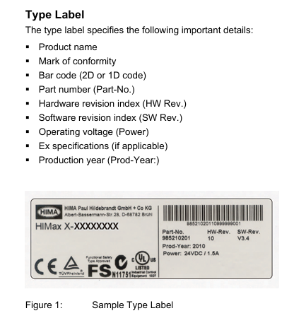
Type label
The type label specifies the following important details:
Product Name
Qualification mark
Barcode (QR code or one-dimensional code)
Part Number (Part Number)
Hardware Revision Index (HW Rev.)
Software Revision Index (SW Rev.)
Working voltage (power)
Explosion proof specifications (if applicable)
Production Year (Production Year:)
Security related processor system
The security related processor module is a 1oo2 processor system. Continuous self inspection ensures safety related operations.
Features:
Two synchronous microprocessors
Specific DDRAM memory for each microprocessor
Testable hardware comparator for data bus
Watchdog (WD)
Gold capacitors for buffering date/time
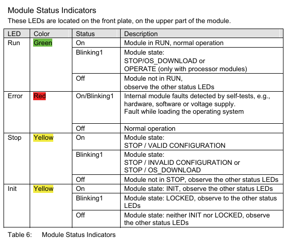
LED used to indicate system status
Mode switch used to configure module behavior when voltage is turned on
The processor module compares data between two processors and triggers an interrupt if the following conditions occur Fault occurred.
The monitor monitors two processors. The self check of the module will also check the watchdog.
system controller
The entire data transmission between various components of the system controller processing module:
Security related processor system
System bus A and B
Ethernet switch with connection interface
memory
This module has RAM and non-volatile memory. Non volatile memory is protected by CRC.
Non volatile memory contains the following programs and information:
operating system
User project
Enable switch, watchdog time, safety time
Online modification
Variables with RETAIN attribute
Production data, if necessary, trim data
Fault status history
event
At startup, the system transfers program code from non-volatile memory to redundant program and data storage.
Alarm and Events
The processor module records alarms and other events in its non-volatile memory.
An event is a change in the state of a variable executed by a factory or controller, with a timestamp provided.
An alert is an event that indicates an increase in potential risk.
The HIMax system records state changes as events at a specified point in time. The X-OPC server transfers events to other systems that display or evaluate events, such as control systems.
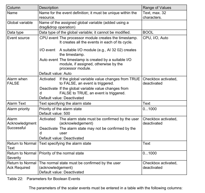
HIMax distinguishes between Boolean events and scalar events.
Boer Event:
The variation of Boolean variables, such as the variation of numerical inputs.
Alarm and normal states: They can be arbitrarily assigned to variable states.
Scalar event:
Exceeding the limit value defined for scalar variables.
Scalar variables have numerical data types, such as INT and REAL.
Two upper limits and two lower limits are possible.
For the limit value, the following conditions must be met:
Maximum limit ≥ upper limit ≥ normal area ≥ lower limit ≥ minimum limit.
Lag may be effective in the following situations: - if the value is below the upper limit. If the value exceeds the lower limit.
Lag is defined as avoiding unnecessary large events when the global variable oscillates strongly near the limit.
Create Event
Both processor modules and certain types of I/O modules are capable of creating events. at
In the following sections, these I/O modules are referred to as SOE modules.
Create events on the processor module
The processor module creates events using global variables and stores them in a buffer, please refer to Chapter 3.4.7. The event is created during the user program cycle.
Create events on the SOE module
The SOE module can create events using input states. The event is created within the SOE module loop.
The SOE module stores events in the intermediate buffer used by the processor module to read them. The intermediate buffer is a part of volatile memory, so if the power is turned off, events will be lost.
Every event that has been read can be overwritten by a new event.
system event
In addition to recording events related to changes in global variables or input signals, the processor and SOE module also create the following types of system events:
Overflow: Due to buffer overflow, some events were not stored. The timestamp of the overflow event corresponds to the timestamp of the event that caused the overflow.
Initialization: The event buffer has been initialized.
Operation mode stop: SOE module changes its operation mode to stop.
Operation mode 'Run': The SOE module changes its operation mode to 'Run'.
Establish communication: Communication between the processor module and SOE module has begun.
Lost Communication: Communication between Processor Module and SOE Module
Terminated.
The system event contains the SRS identifier of the module that caused the event.
state variable
State variables provide the state of scalar events for user programs. Each of the following states is connected to a state variable that can be assigned a BOOL type global variable:
Normal.
Exceeding the lower limit.
The minimum limit has been exceeded.
Exceeding the upper limit.
The maximum limit has been exceeded.
When the corresponding state is reached, the assigned state variable becomes TRUE.
Recording events
Processor module collects events:
Created by I/O module
Created by the processor module itself
The processor module stores all events in its buffer. A buffer is a part of non-volatile memory with a capacity of 5000 events.
The processor module arranges events from different sources based on their arrival time, rather than sorting them by timestamp.
If the event buffer is full, as long as no other events are read and marked as overwritten, new events cannot be stored.
OPC servers can read events and provide them to external systems for evaluation and storage.
Mode Switch
The mode switch defines the behavior of the processor module when it restarts.
The processor module will restart in the following situations:
Automatic: - When connected to working voltage - After severe malfunction - After loading the operating system
During the operation, use the corresponding commands on PADT.
The mode switch has three different switch positions:
initialization
stop
run
The switch position during normal operation is in operation.
Switch position: initialization
The Init switch position is used to set the processor module to LOCKED state. In this state, the settings previously configured for the module cannot be accessed anymore. For example, if the administrator password is unknown, this operation may need to be performed.
In the locked state, the module is reset to factory settings:
Default SRS, slot number depends on the slot used
Default IP address and IP settings
Only administrator user accounts with empty passwords can access
Enable the switch set to default value
The modified settings in this state will overwrite the factory settings and all previously used settings!
If the settings remain unchanged, the previously saved settings (switch not set to Init) will be used when restarting the module.
start
To start the processor module, insert it into the allowed motherboard slot. If the substrate is already running, the processor module will start and adopt the operating state set through its configuration and mode switch position. If the substrate is not working, please connect the power supply voltage.
install
When installing the processor module, please pay attention to the following points:
This module is designed for use with HIMax substrates. For more information about the bottom plate structure, please refer to the corresponding system documentation.
Operate the processor module only in the expected slot
Only the forced cooling (X-FAN) operation module can be used.
Only use appropriate connector boards to operate the module.
The effect of removing and inserting modules:
When disassembling the module, the connector board remains in the HIMax substrate.
Since all external interfaces are connected through the module's connector board, the module can be replaced without affecting the external interfaces
The SRS of the module is stored on the connector board and becomes SRS after the module is inserted.
The effect of removing the plug
Pulling out the plug will interrupt external communication.
Take appropriate grounding measures.
User Program
The application program functions that PES should execute are specified in the user program. PADT is used to create and compile project configurations using user programs, and load them into processor modules.
Start processor module
The processor module can be started as follows:
Insert it into the substrate that provides working voltage
Open the working voltage of the substrate for inserting the module.
The behavior at module startup depends on:
Position of mode switch
There are additional redundant processor modules present
There are valid project configurations (including user programs) in non-volatile memory
When the switch is set to stop or run, the processor module will check if there are any other processor modules present
If there are no other processor modules, the module will start running separately.
If there is at least one additional processor module, the module attempts to automatically start operating using the configuration of the existing processor module. Maintain a safety rope.
- YOKOGAWA
- Reliance
- ADVANCED
- SEW
- ProSoft
- WATLOW
- Kongsberg
- FANUC
- VSD
- DCS
- PLC
- man-machine
- Covid-19
- Energy and Gender
- Energy Access
- Renewable Integration
- Energy Subsidies
- Energy and Water
- Net zero emission
- Energy Security
- Critical Minerals
- A-B
- petroleum
- Mine scale
- Sewage treatment
- cement
- architecture
- Industrial information
- New energy
- Automobile market
- electricity
- Construction site
- HIMA
- ABB
- Rockwell
- Schneider Modicon
- Siemens
- xYCOM
- Yaskawa
- Woodward
- BOSCH Rexroth
- MOOG
- General Electric
- American NI
- Rolls-Royce
- CTI
- Honeywell
- EMERSON
- MAN
- GE
- TRICONEX
- Control Wave
- ALSTOM
- AMAT
- STUDER
- KONGSBERG
- MOTOROLA
- DANAHER MOTION
- Bentley
- Galil
- EATON
- MOLEX
- Triconex
- DEIF
- B&W
- ZYGO
- Aerotech
- DANFOSS
- KOLLMORGEN
- Beijer
- Endress+Hauser
- schneider
- Foxboro
- KB
- REXROTH
- YAMAHA
- Johnson
- Westinghouse
- WAGO
- TOSHIBA
- TEKTRONIX
- BENDER
- BMCM
- SMC
- HITACHI
- HIRSCHMANN
- XP POWER
- Baldor
- Meggitt
- SHINKAWA
- Other Brands
- UniOP
- KUKA
- IBA
- Beckhoff
-
ADLINK CPCI-6860A - 51-31310-OB10 industrial motherboard CompactPCI SBC
-
ADLINK AmITX-SL-G-H110 - 51-7A104-0A30 Mini-ITX Industrial Motherboard
-
ADLINK PXI-2005-003 - CPCI Industrial PC Data Acquisition Card Multi-Function DAQ
-
ADLINK DININ-814M - 51-14032-0A3D SCSI-100P cable connection Interface Terminal Board
-
ADLINK CPCI-3920NA/C2D15/M1G - 3U CompactPCI Intel Core 2 Duo Single Board Computer
-
ADLINK PCIE-8560 - 51-18014-0A20 Communication Card High Speed DAQ
-
ADLINK PCI-C154+ - Motion Control Card 4-axis Motion Controller Board
-
ADLINK PCI-RTV24 - image capture card Analog Video Frame Grabber
-
ADLINK NuPRO-842LV/P - 51-41360-0B30 Industrial Motherboard CPU Board
-
ADLINK cBP-3208/3208R - CPCI Board 3U 8-Slot CompactPCI Backplane
-
ADLINK PCI-8164 - 4-Axis Motion Controller PCI Card 51-12406-0A40
-
ADLINK PCIe-GIE64+ - 4-CH GigE Vision PoE+ Frame Grabber Video Capture Card
-
ADLINK CPCI-6860 / 6860A - CompactPCI Dual Xeon Single Board Computer
-
ADLINK IEC-915GV - REV 1.1 Industrial motherboard CPU Board
-
ADLINK ND-6520 - Technology RS-232 to RS-422RS-485 Converter NuDAM Module
-
ADLINK RTV-24 / PCI-MP4S - 51-12519-1C30 4-Channel Real Time Video Capture Board
-
ADLINK cPCI-6910 / cPCI-6910AM/M1G - cPCI-6910AM/DXL16/M1G/S80G(G)-3120 BOARD CompactPCI SBC
-
ADLINK NUPRO-A40H - Linghua 51-41807-1A30 Industrial Control Computer Motherboard
-
ADLINK USB-3488A - USB to GPIB INTERFACE USB-3488A(G) Controller Module
-
ADLINK PCI-8134A - motion control card 4-Axis Controller Card
-
ADLINK PCI-8134 - 51-12403-0B20 PCB Board Motion Controller Card
-
ADLINK LPCI-3488A - PCI Card 51-12801-0A30 Low Profile IEEE-488 GPIB Card
-
ADLINK NUPRO-900A - industrial computer motherboard Single Board Computer
-
ADLINK cPCI-6840V - industrial control motherboard CompactPCI SBC
-
ADLINK M-342 - industrial motherboard ATX Mainboard
-
ADLINK NUPRO-935A/LV - industrial control motherboard
-
ADLINK cPCI-3538 - CompactPCI Async Serial Communications Module
-
ADLINK PCI-1610 - Card 4-Port RS-232 PCI Serial Communication Card
-
ADLINK HSL-DI32-DB-N - Distributed I/O Module 32-CH Digital Input
-
ADLINK CPCI-6860A - motherboard E7501 CompactPCI Single Board Computer
-
ADLINK PCI-8134A - 4-Axis Motion Control Card PCB Board
-
ADLINK EURESYS LINK - grabbers Video Capture Card Frame Grabber
-
ADLINK NuPRO-965DV - motherboard Industrial Control Board
-
Thermo Fisher Scientific 80100-60500 - 80000-61010R 80000-21000R 80000-60457 Spectrum System Controller ADLINK Components
-
ADLINK PCI-7296 - IO card High Density 96-CH Opto-Isolated DIO Card
-
ADLINK MXC-6322D - Matrix Industrial Computer Fanless Embedded PC
-
ADLINK DIN-825-GP4 - connector board Terminal Block Interface
-
ADLINK AMP-208C - Motion Control Card DSP-based 8-axis
-
ADLINK PCIe-GIE72 - 51-18531-0A10 2-CH GigE Vision Frame Grabber PoE+ Card
-
ADLINK PXIS-3320 - PXI/PXIe Chassis 15-slot 6U PXI/CompactPCI SEM-I-1518=9N41
-
ADLINK MI-965 - Industrial CPU Motherboard
-
ADLINK M-302 - Industrial control motherboard
-
ADLINK PCI-6308V - 51-12202-0A50 Isolated Analog Output Card PCB-I-E-1813=ZA03
-
ADLINK NUPRO-935A - Industrial Mother Board CPU Board
-
ADLINK PCI-7434 - PLOTECH Digital Output Card PCB-I-E-1182=6EX2
-
ADLINK PCI-7432 - 64 Channel Isolated Digital I/O PCI CARD
-
ADLINK NUPRO-935A/DV - 51-41802-0A10 motherboard Industrial Control Board
-
ADLINK PCIe-GIE72 - 51-18531-0A10 2-CH GigE Vision Frame Grabber PoE+ Card
-
ADLINK HSL-DI16DO16-M-NN - HSL-DI16DO16-M-NN(G)-0280 Discrete I/O Module Distributed I/O
-
ADLINK cPCI-6760D / cPCI-6840V - cPCI Single Board Computer Industrial Motherboard
-
ADLINK NuPRO-A301 - Motherboard IPC Motherboard
-
ADLINK NuPRO-935A/LV - motherboard Industrial Control Board
-
ADLINK NUPRO-E320LV - motherboard Industrial Control Board
-
ADLINK NuPRO-E42 - Industrial Control Board Motherboard
-
ADLINK M-342 - ATX Motherboard Industrial PC Mainboard
-
ADLINK CPCI-6860 / 6860A - Industrial Control Motherboard CompactPCI SBC
-
ADLINK AmITX-SL-G-Q170/GEHC(EA)-021E - 51-7A104-0A20 Industrial Motherboard w/ DDR4
-
ADLINK NUPRO-852 / NUPRO-852LV - industrial control motherboard
-
ADLINK DAQ-2006-004 - Multi-Function DAQ Cards Data Acquisition
-
ADLINK PCIe-RTV24 - Frame Grabbers Video Capture Cards PCI-e x1 4-CH 120fps
-
ADLINK PCI-8134 - 51-12403-0B20 4-Axis Motion Controller Card
-
ADLINK PCI-8132 - 2-Axis Motion Controller Card
-
ADLINK cBP-6402 - Backplane Passive Backplane
-
ADLINK cPCI-6760D - cPCI Single Board Computer Industrial Control Motherboard
-
ADLINK DIN-825-4PO(G)-0030 - Terminal Board Motion Control Breakout Board
-
ADLINK M-322 - Industrial Motherboard
-
ADLINK ABX-1301 - 51-63808-0A20 Industrial Motherboard
-
ADLINK PCI-7433 - 64-CH Isolated Digital Input Card
-
ADLINK AMP-208C - Motion Control card
-
ADLINK DIN-50S-01 - TECHNOLOGY TERMINAL BLOCK INTERFACE MODULES W/ DIN RAIL
-
ADLINK PCI-8134 - 51-12403-0B20 4-Axis Motion Controller Card
-
ADLINK MXE-201/MSSD64G - Technology Automation Computer Fanless Embedded System
-
ADLINK USB-3488A (G) - USB to GPIB CARD Controller Interface
-
ADLINK cPCI-3720L2 - SBC Single Board Computer PCB AMAT 0190-14599
-
ADLINK PCI-7251 - Relay Output Board Expansion Module
-
ADLINK PCI-8124-C - PCB Board 4-CH Encoder Trigger Card
-
ADLINK HD636 - Industrial Computer Board PCB-I-E-2200=9L32-2 Main Board
-
ADLINK USB-3488A - THERMOTRON INDUSTRIES IEEE 488 CPU INTERFACE WITH USB/GPIB
-
ADLINK MI-965 - motherboard Industrial CPU Board
-
ADLINK LPCIe-7250 - Technology Digital IO card Low Profile PCIe Relay Output
-
ADLINK NuPro-720/SCOPUS - Technology With 256MB Industrial MotherBoard
-
ADLINK NuPR0-840 - industrial control motherboard
-
ADLINK M-342 - Motherboard ATX PC Mainboard
-
ADLINK MI-965 - motherboard Industrial CPU Board
-
ADLINK CPCI-6530V/4402E/M4G - AMAT CPCI-6503VED/4402E/M4-0/SD64G-2550 Universal SBC
-
ADLINK IMB-M43-IRV - Industrial Motherboard ATX PC Board
-
ADLINK 52983 / 58183 - Chroma PXI I/O Input/Output Card + Carrier Adapter
-
ADLINK PXI-3920 - PXI 3U cPCI Industrial Controller w/ RAM SSD Embedded CPU
-
ADLINK NuPRO-842LV/P - motherboard Industrial Control PC Board
-
ADLINK PCI-7442 - 64-Channel Datalogging Acquisition Switch Card
-
ADLINK PCIe-RTV24 - Cadre Agrippeurs Vidéo de Capture Cartes Pci-E x1 4-CH
-
ADLINK ACL-7122A - TECHNOLOGY 51-11004-1A1 CIRCUIT BOARD 96-CH DIO Card
-
ADLINK PCIe-RTV24 - 51-18016-0A20 Image Acquisition Video Capture Card
-
ADLINK AMP-204C - DSP-Based 4-Axis Advanced Pulse-Train Motion Controller
-
ADLINK 52981 / 58183 - Chroma PXI Digital I/O DIO Input/Output Card + Carrier Adapter
-
ADLINK PCI-8102 - motion control card 2-Axis
-
ADLINK NuPRO-E320LV - industrial computer motherboard
-
ADLINK PCI-RTV24 - card Analog Video Capture Frame Grabber
-
ADLINK M-302 - Motherboard P/N: 08GSAQ96501102
-
ADLINK NEON-1020 - Smart camera Industrial Machine Vision
-
ADLINK AMP- 208C - card DSP-based 8-axis Motion Controller
-
ADLINK PCI-9114DG - Multi-Function Daq Card Data Acquisition
-
ADLINK MXC-6322D/BE_FanG) - Matrix PM2-MXC Fanless Embedded Computer
-
ADLINK DIN-825-4P0 - Terminal Board Motion Control Breakout Board
-
ADLINK HPCI-8S4 REV.B2 - Industrial Control Base Plate Passive Backplane
-
ADLINK HSL-DI32-DB-N - Distributed I/O Module 32-CH Digital Input
-
ADLINK NuPRO-935A/DV - industrial control motherboard
-
ADLINK PCI-7442 - Switch card 64-CH Datalogging Acquisition Card
-
ADLINK NuPRO-E42 - motherboard 51-41808-0A30 Industrial Motherboard
-
ADLINK CPCI-3610D/N45/M1G(G)-10B0 - CompactPCI Intel Atom Single Board Computer CPU Board
-
ADLINK LPCI-7250 - GP Output Isolated Digital Input Card PCB 51-12803-0A10
-
ADLINK PCI-7250 - 51-12007-0A40 PCI7250 8-CH Relay Output & 8-CH Isolated DI Card
-
ADLINK STC-1005 - 10.4inch touch panel PC E3845 CPU
-
ADLINK PCI-FIW64 - image card FireWire Frame Grabber
-
ADLINK NuPRO-935A/LV - industrial computer motherboard
-
ADLINK PCI-8164 00B0 - Centralized Motion Controller 4-axis PCB-I-E-1179=6EX2
-
ADLINK ACLD-9137F REV A1 - 51-14006-101 Screw Termination Board
-
ADLINK PCI-7248 - 51-12006-0A40 Control Card Digital I/O
-
ADLINK HPCI-8S4 - Technology Backplane PCB GaSonics 3500 Asher Passive Backplane
-
ADLINK NuPRO-E320LV - Cpu Board 51-41804-0A20 Industrial Motherboard
-
ADLINK HPX-13S4 - device baseboard Passive Backplane
-
ADLINK M-322 - industrial motherboard
-
ADLINK NuPRO-865 REV :3.0 - industrial motherboard
-
ADLINK DIN-68S-01 - Terminal Block Interface Module Cable Connection
-
ADLINK ETX-IM266-C100Z - motherboard ETX CPU Module
-
ADLINK NuPRO-E320LV - motherboard Industrial Control Board
-
ADLINK NuPRO-841 REV:2.0 - motherboard Industrial PC Board
-
ADLINK ETX-AT-N270-18 - N270 Board ASH-EAT-18/S512 ET Mainboard

K-JIANG

Add: Jimei North Road, Jimei District, Xiamen, Fujian, China
Tell:+86-15305925923