
K-WANG


ABB AC500 Series PLC Module Wiring Guide Manual
ABB AC500 Series PLC Module Wiring Guide Manual
The ABB AC500 series PLC module wiring guide focuses on the wiring, installation, and safety specifications of various IO modules in this series of PLCs, covering multiple types of modules such as switch quantity, analog quantity, hybrid module, position module, bus interface module, CPU integrated IO, and communication card. It clarifies the terminal allocation, electrical connection method, power requirements, and anti-interference measures of each module, emphasizes safety points such as power-off operation, correct grounding, and cable selection, and details core concepts such as source/drain type differences and analog wiring system differences, providing comprehensive wiring technical support for PLC system construction.
Document Overview
Basic positioning
The document is a module wiring guide for ABB AC500 series PLC, with the core goal of standardizing the wiring and installation process of various IO modules to ensure stable system operation.
The target audience needs to have basic knowledge of AC500 system and Control Builder Plus/CoDeSys programming, and practical applications need to be adjusted according to the on-site situation.
core principle
Safety priority: All operations must be powered off to avoid overvoltage, short circuit, and grounding circuit risks.
Compatibility: The module supports source/drain input/output, multiple communication protocols, and adapts to different scene requirements.
Anti interference: Reduce the impact of electromagnetic interference through cable selection, wiring specifications, and grounding design.
Core Basic Concepts
(1) Interference processing and wiring
Interference type protection measures
The distance between strong and weak electrical interference is ≥ 20cm (220V/10A or above ≥ 60cm), and weak electrical interference is located below the cable trench
Separate installation of interference PLC and high-voltage electrical appliances inside the cabinet, and separate routing of IO lines and high-power lines in separate slots
RC filter for signal line interference and differential mode interference, differential amplifier+shielded wire for common mode interference
Frequency converter interference, isolation transformer, filter, and output reactor installed nearby
(2) Grounding specifications
Safe grounding: The grounding terminal of the power cord is connected to the cabinet to prevent electric shock and injury.
System grounding: The controller and the controlled equipment have the same potential, and the grounding resistance is ≤ 4 Ω.
Signal grounding: Switching quantities do not require grounding, analog quantities require single point grounding; Shielded wire can be grounded on one side (high-frequency can be grounded on both ends).
Communication grounding: GND grounding for non isolated 485 communication, single point grounding for isolated communication, using shielded twisted pair cables.
(3) Source leakage type and analog line system
Difference between source and drain types
Leakage type (NPN): When the signal is triggered, OUT and GND are conductive, and the COM terminal is connected to the positive pole of the power supply.
Source type (PNP): When the signal is triggered, OUT and VCC are conductive, and the COM terminal is connected to the negative terminal of the power supply.
Analog line system
Two wire system: The power supply and signal share two wires, and the sensor is passive and powered by the module.
Three wire system: Short circuit the power supply negative wire to the signal negative wire, with a power greater than that of the two wire system, and cannot be explosion-proof.
Four wire system: Two wires each for power and signal, active sensors, high measurement accuracy.
Discrimination method: Disassemble the module wires and measure the current with a multimeter. If there is a signal, it is a four wire system; if there is no signal, it is a two wire system.
Core parameters and wiring of various modules
(1) Switching module
Module type represents model, core specifications, wiring points
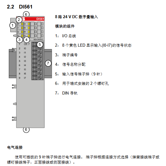
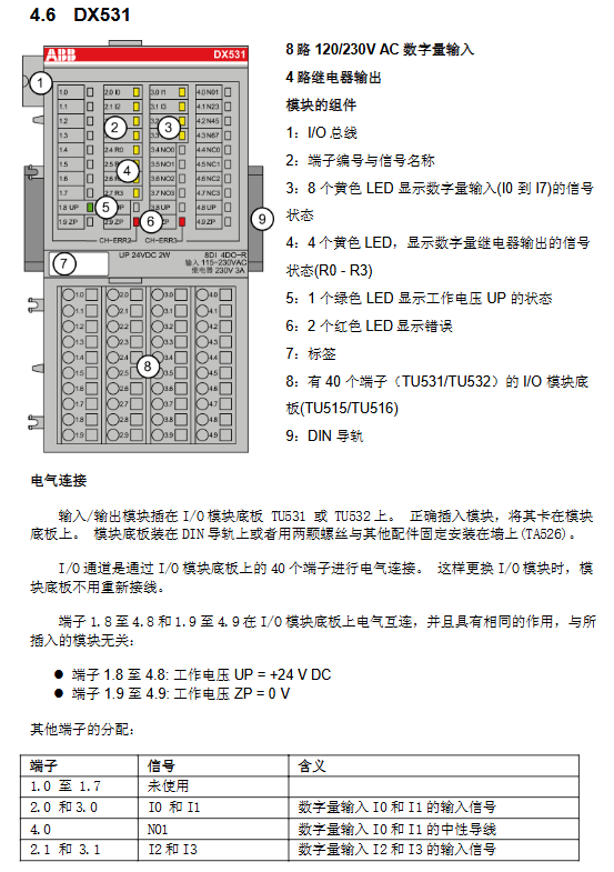
Input module DI524 32 channel 24V DC terminal 1.8-4.8 connected to UP (24V), 1.9-4.9 connected to ZP (0V)
Output module DO561 8-channel 24V DC transistor (0.5A) external power supply connected to UP/ZP, requiring 3A fast melting protection
Combination module DC522 16 channel configurable IO supports sensor power output (24V DC/0.5A)
(2) Analog quantity module
Core parameters
Resolution: AI523 (12 bits+sign bit), AI531 (15 bits+sign bit), AO561 (11/12 bits).
Support signals: voltage (0-10V, -10~+10V), current (4-20mA, 0-20mA), thermistor (Pt100/Pt1000), thermocouple (J/K/S type).
Wiring requirements
Analog signals require shielded cables, with both ends of the shielding layer grounded.
The three wire system of thermal resistance requires the occupation of two adjacent channels, with the same cross-sectional area of the wires.
Passive sensors are supplied with constant current by modules, while active sensors require independent power supply.
(3) Bus interface and communication card components
Module model, protocol type, core function, bus speed
CI501-PNIO PROFINET 4AI+2AO+8DI+8DO -
CI541-DP PROFIBUS 4AI+2AO+8DI+8DO -
CM572-DP PROFIBUS DP main station communication up to 12MBit/s
CM575-DN DeviceNet main station communication up to 500kBit/s
(4) CPU integrated IO module
Model, Digital Input, Digital Output, Analog Input, Analog Output
PM554 8-way 24V DC 6-way (transistor/relay) --
PM564 6 channels 24V DC (expandable to 8 channels) 6 channels (transistors/relays) 2 channels (0-10V) 1 channel (0-10V/4-20mA)
Safety operation standards
General Requirements
Before all wiring and module replacement operations, the power supply voltage and operating voltage must be turned off.
The module terminal can carry a maximum voltage of 240V AC, and it is necessary to avoid the risk of electric shock. Before operation, confirm that the power is turned off.
protective measures
The IO channel has protection against reverse connection, inversion, short circuit, and continuous overvoltage (up to 30V DC).
The output module does not have built-in short-circuit/overload protection and requires an external 3A (transistor output) or 5A (relay output) fast melting fuse.
Grounding and shielding
The signal line needs to have a unique reference ground to avoid forming a ground loop.
Shielded cables need to be grounded locally or at a single point in the control room in situations where conductive interference may occur.
- YOKOGAWA
- Reliance
- ADVANCED
- SEW
- ProSoft
- WATLOW
- Kongsberg
- FANUC
- VSD
- DCS
- PLC
- man-machine
- Covid-19
- Energy and Gender
- Energy Access
- Renewable Integration
- Energy Subsidies
- Energy and Water
- Net zero emission
- Energy Security
- Critical Minerals
- A-B
- petroleum
- Mine scale
- Sewage treatment
- cement
- architecture
- Industrial information
- New energy
- Automobile market
- electricity
- Construction site
- HIMA
- ABB
- Rockwell
- Schneider Modicon
- Siemens
- xYCOM
- Yaskawa
- Woodward
- BOSCH Rexroth
- MOOG
- General Electric
- American NI
- Rolls-Royce
- CTI
- Honeywell
- EMERSON
- MAN
- GE
- TRICONEX
- Control Wave
- ALSTOM
- AMAT
- STUDER
- KONGSBERG
- MOTOROLA
- DANAHER MOTION
- Bentley
- Galil
- EATON
- MOLEX
- Triconex
- DEIF
- B&W
- ZYGO
- Aerotech
- DANFOSS
- KOLLMORGEN
- Beijer
- Endress+Hauser
- schneider
- Foxboro
- KB
- REXROTH
- YAMAHA
- Johnson
- Westinghouse
- WAGO
- TOSHIBA
- TEKTRONIX
- BENDER
- BMCM
- SMC
- HITACHI
- HIRSCHMANN
- XP POWER
- Baldor
- Meggitt
- SHINKAWA
- Other Brands
- UniOP
- KUKA
- IBA
- Beckhoff
-
LTI SC52.0040.0012.0000.0 - Servo Drive
-
Lti SC52.0040.0012.0000.0 - Servo Drive
-
Milton Industries LTI Tool By Milton LT1240 - 1/2" Drive Lugnut Remover
-
LTi Drives SO84.200.P030.0000.0-W - Servo Spindle Drive
-
LTI DRIVES LSP08-035-320-30-B0R1PY170 - Servo Motor
-
LTI DRIVES SE84.200.SC00.0001.0-W - Servo Drive
-
Lust CDE34.005.W2.2 - Lti Drives Controller
-
LTi SO84.012.0030.0011.2 - ServoOne Servo Drive
-
LTi Drives SO CM-P.0010.11.00.0 - Servo Drive Controller
-
LTi CDE34.017.W3.0 - Servo Drive
-
LTI Drives CDB32.004, C2.0,SH - Positioning Controller
-
LUST CM-CAN1 - LTi DRIVES Communication Module
-
LTi SO84.012.1030.0000.2 - Servo Drive
-
LTI MOOG CDE54.044 - PITCHMASTER FREQUENCY CONVERTER 181-01019
-
MOOG LTI 181-01019 CDE54.044 - PITCHMASTER FREQUENCY CONVERTER
-
Lust LTi Drives CDE34.010,D2.0 - Servo Drive Controller
-
LTI SO84.032.0003.0101.2 - Servo Drive
-
Seagate 9CC132-302 Harris LTI-CS IRT-34-0021-01 - Hard Drive 160GB
-
LTI SO84.032.0003.0001.2 - Servo Drive
-
LTI SO24.007.0070.0000.1 - SERVO CONTROLLER
-
LTi drive CDA32.003.C3.0.H05-01.PC1 - Servo Drive
-
LTI SO84.016.0030.0000.2 - SERVO CONTROLLER
-
LUST LTI CD A34.008,W1.4, BR - SERVO DRIVE
-
MOOG LTI 181-01019 CDE54.044 - PITCHMASTER FREQUENCY CONVERTER
-
LTI MOOG 181-01019 - PITCH Master Servo Drive CDE54.044
-
LTI SERVO ONE SO84.045.0030.0001.2-W - Drive
-
LUST LTi SO84.032.0040.0000.2 - SERVO ONE DRIVE
-
LTi Drives LSH-074-2-30-3 20/T1,G6.1M - SERVO MOTOR
-
LTI SO84.016.0000.0101.2 - servo drive
-
LTI SA54.0550.0033.0000.0 - Servo Drive
-
LTI SA54.0550.0033.0000.0 - Servo Drive
-
LTI LT 4850 - 3/8" Drive 3-Pc Twist Socket Transmission Drain Plug Removal System
-
LTI Tools LT4400-30 Lock Technology - 3/4" Twist Socket 1/2" Drive Lugnut Remover
-
LTI Tools LT-1400C - 1/2 Drive Wheel Torque Extension Tool
-
LTI Tools LT1250 - 1/2" Drive Dual Sided Socket Lug Nut Remover Tool
-
LTI SO84.032.0003.0101.2 - Servo Drive
-
LTI MOOG 181-01019 - PITCH Master Servo Drive CDE54.044
-
MOOG LTI 181-01019 CDE54.044 - PITCHMASTER FREQUENCY CONVERTER
-
MOOG LTI 181-01019 CDE54.044 - PITCHMASTER FREQUENCY CONVERTER
-
MOOG LTI 181-01019 CDE54.044 - PITCHMASTER FREQUENCY CONVERTER
-
LTI SA54.0550.0033.0000.0 - Servo Drive
-
LTI Tools LT-4800 - 7 Piece Twist Socket 3/8" Drive Oil Drain Plug Removal Set
-
LTI SA54.0550.0033.0000.0 - Servo Drive
-
LTI Drive SO24.007.00300000.0 - Servo Drive
-
LTI TOOLS LTI 1400-I - Drive Wheel Torque Extension
-
LTI Tools LT4400-3 - 3/4" 19mm Twist Socket 1/2" Drive Lugnut
-
LTI TOOLS LTI 1400-BB - Drive Wheel Torque Extension
-
LTI SO84.032.0003.0101.2 - Servo Drive
-
LTI Tools LT-4512 - 3/8" Drive 12mm Twist Socket
-
LTI MOTION Luster SO84.032.0003.0001.2 - Servo Drive
-
LTI Tool By Milton LT1600P - 1" Drive Torx Stick
-
LTI Lust VF1424L,HF,OP2,S56 - Variable Frequency Drive
-
LUST CDA32.004,C1.4,H08,B0 - SERVO DFRIVE CM-CAN1 Module
-
LTI SO84.045.0002.0001.2-W - Drive
-
LTI Lust VF1404M,C9,PT1,BR1 - Inverter Type VF1404M
-
LTI SA54.0550.0033.0000.0 - Servo Drive
-
LTI Tools LT-1400C - 1/2" Drive Wheel Torque Extension
-
Lust LTI DRiVES CDA32.006, C3.0, H09 - Variateur De Fr茅quence Frequency Inverter
-
LTI MOOG CDE54.044 - PITCH master SERVO DRIVE
-
LTI MOOG CDE54.044 - PITCH master SERVO DRIVE
-
LTI SO84.143.0020.0101.2-W - servo drive
-
LTI MOTION SC34.0200.0011.0000.0 - Servo drives
-
LTI SO84.032.0003.0001.2 - Servo Drive
-
LTI DRIVES GmbH MS100 - Assembly Set Mounting Kit
-
LTI SO84.032.0003.0001.2 - Servo Drive
-
LTI SO84.032.0003.0001.2 - Servo Drive
-
LTI MOTION SO84.032.0003.0101.2 - servo drive
-
LTI SO84.032.0003.0101.2 - Servo Drive
-
LTI MOOG CDE54.044 - PITCH master SERVO DRIVE
-
LTI MOTION CDE32.004.C2.4 - Servo drives
-
LTI CDD34.032锛學x.x锛孊R锛孭C1 - Servo Drive
-
Lust LTI DRiVES CDA32.006, C3.0, H09 - Inversor De Frecuencia Frequency Inverter
-
Lust SO84.008.0030.1000.0 - Servo One LTi Drive
-
LTI MOTION SO84.032.0003.0101.2 - Servo drives
-
LUST LTi CDA32.004,C1.4 - SERVO DRIVE
-
LTI MOOG CDE54.044 - PITCH Master SERVO DRIVE
-
LTI KEBA CDB32.004 C2.7, SH - PN: 08673530 Frequency Inverter
-
LTI Tools LT-1400C - 1/2" Drive Wheel Torque Extension
-
LTI LT1400-E - 1/2" Drive Wheel Torque Extension
-
LTI MOOG 181-01019 - PITCH master SERVO DRIVE CDE54.044
-
LTI LSN-097-0510-30-560/T1 - Actuator Motor
-
LTI Tools LT 4800 - 7 Piece 3/8" Drive Twist Socket Oil Drain Plug Removal System
-
LTI DRIVES GmbH MS100 - MONTAGESET Assembly Set Mounting Kit
-
Lti SC52.0040.0012.0000.0 - Servo Drive
-
LTI DRIVES GmbH MS100 - Juego De Montaje Assembly Set Mounting Kit
-
LTi DSM4-14.2-21R83-200 - Drives servomoteur Servo Motor
-
MOOG CDE 54.044.GDA - Pitch Master Industrielle Turbine Lti Drive
-
LTI SO24.004.0030.1000.0 - Servo Drive Controller
-
Lti MOOG CDE54.044 - Pitch Master Servo Drive
-
Lust LTI DRiVES CDA32.006, C3.0, H09 - Inverter
-
LTI MOTION GMBH CDB34.006,W3.0,PC1,H39 - Frequency inverter
-
LTI SO84.032.0003.0001.2 - Servo Drive
-
MOOG CDE 54.044.D - Pitch Master Industrielle Turbine Lti Drive
-
LTI TOOLS LT-1460 - 1/2" DRIVE WHEEL TORQUE EXTENSION KIT 5 PIECE SET
-
Lust Cdb32.003, C2.4 - Lti Drives Servoregulador Frecuencia Servo Controller Inverter
-
Lust LTI DRIVES CDA32.006, C3.0, H09 - Frequency Inverter
-
Lust Lti SO82.004.0030.0000.2 - Servo Drive
-
LTI MOTION SC34.0200.0011.0000.0-SL - Servo drives
-
LTI MOTION SA54.0075.0033.0000.0 - Servo drives
-
LTI MOTION SC32.0075.1011.0000.0 - Servo drives
-
LTI Servo-One Junior SO22.006.0080.1000.0 - Servo Controller Servoregler
-
LUST CDA32.004, C1.4, H08, B0 - Servo Drive & LTI CM-CAN1 Module
-
LTI DRIVES LSP08-035-320-30-B0R1PY170 - Servo Motor
-
LUST LTI CDA32.004,C1.4.H08.B0 - SERVO CONTROLLER DRIVES
-
LUST LTi DRiVES CDS44.072LC1.2 - Servo Drive
-
Lti Servo-One Junior SO22.006.0082.1000.0 - Servo Controller Servoregler
-
LUST CDA32.008,C2.0,HF - Lti DRIVES Spindle Drive Inverter
-
LTI SO22.003.0082.0000.0 - Servo Drives One junior Servo Controller Servoregler
-
Lust Lti Drives CM-CAN1 - Communication Module
-
LUST Lti Drives Vf1202s, G8, I6 - Frequency Inverter Drive
-
LTI DRIVES BR-090.03.540.UR.H38 - Bremswiderstand Brake Resistor
-
LTi DRIVES PM-E40.2DRA054P - Wind Turbine Pitch Control Inverter
-
LTi Drives GmbH br-110.01.540-UR - Brake Resistor
-
LTI Drives LSN-097-0960-30-0560/T1,S4,B - Servo Motor
-
LUST CDA34.006.C2.0 - LTI Drives Servoregler
-
LUST LTI DRIVES SERVO ONE JUNIOR SO24.002.0020.0000.1 - Servo Drive Controller
-
LTI MOTION SO84.032.0003.0001.2 - Servo drives
-
LTI DDTD750V2-120 - IBOP ACTUATOR CYLINDER FOR TOP DRIVE
-
LTI CDE32.004, C2.4 - SERVO DRIVE
-
LUST LTI DRIVES CDD34.017 W3.4PC1 - Servo Drive Controller
-
LTI CDA3208,C3,0,HF - AC SERVO DRIVE
-
LUST LTI DRIVES LSH-074-3-30-560/T1,G6.1S - SERVO MOTOR
-
LUST Lti CDB32.004.C2.4.SH - AC Servo Drive
-
LTi CDA32.006, C3.0, H09 - Servo Drive
-
LTI SO22.003.0010.0000.0 - Servo Drive Servo one junior Servoregler Controller
-
LTi Drives DSM4-14.2-21R83-200 - Servo Motor
-
LUST Lti Drives Lsh-097-1-30-560/T1, 1R - Servomotor
-
LTI 1237 - 7 Piece 1/2" Drive Flip Socket Set

K-JIANG

Add: Jimei North Road, Jimei District, Xiamen, Fujian, China
Tell:+86-15305925923