
K-WANG


Johnson AE55/NIE55 Installation Guide
Johnson AE55/NIE55 Installation Guide
Equipment Overview and Application Scenarios
core positioning
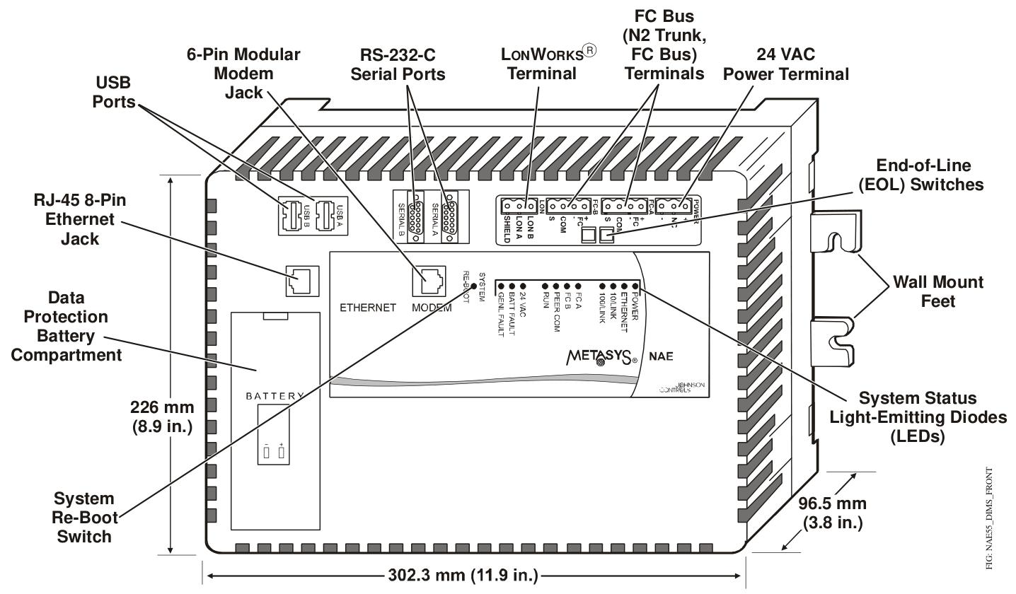
NAE (Network Automation Engine) and NIE (Network Integration Engine) are monitoring devices that support web access and are based on Ethernet. Their core functions are to monitor and control on-site building automation equipment, HVAC equipment, and lighting systems. Unless otherwise specified in the document, the MS-NAE55xx-x and MS-NIE55xx-x series are collectively referred to as NAE55.
Emission compliance requirements
United States: Compliant with FCC Part 15 Class A digital device restrictions, only applicable to commercial environments. If interference occurs in residential environments, users need to resolve it themselves.
Canada: Meets the requirements of the Canadian Interference Equipment Regulations (R è glement sur le mat é riel brouilleur du Canada).
Preparation before installation
Package contains components
1 NAE55 host
1 data protection battery (individually packaged)
1 installation manual
Required materials and specialized tools
4 fasteners for compatible mounting surfaces (M4 screws for Europe, # 8 screws for North America)
2 sections of DIN rails 36 centimeters (14 inches) and above (only for DIN rail installation scenarios)
1 small flathead screwdriver (used to fix the communication cable of the terminal block)
Installation environment requirements
Stay away from corrosive gases and follow the environmental restrictions specified in the technical specifications.
Avoid installing on surfaces that are prone to vibration (such as pipelines) or near electromagnetic interference sources (to prevent interference with communication).
Reserve sufficient space for wiring and terminal connections (refer to size requirements in Figure 2).
The power supply should not be installed below NAE55.
When installing panels/enclosures, it is necessary to avoid sealing the enclosure and ensure that the enclosure walls or transformers do not obstruct the equipment ventilation openings.
Devices that cause the temperature of the NAE55 processor to exceed 77 ° C (171 ° F) must not be added inside the casing (embedded temperature sensor data must be viewed through diagnostic tags).
Installation process
Installation method selection
NAE55 supports three installation methods: wall mounting, DIN rail mounting, and shell mounting. The core operations are as follows:
1. Wall installation (vertical surface)
Mark the four installation hole positions on the wall according to the dimensions in Figure 3 (horizontal installation hole spacing of 317.5mm, vertical installation hole spacing of 63.5mm) or directly using the host as a template.
After drilling, if anchor bolts need to be fixed, they should be inserted into the holes. First, screw the screws into the top two holes, leaving enough space to accommodate the installation feet.
When installing horizontally, hang the top mounting foot of the host on the screw; When installing vertically, the host needs to be held in a fixed position.
Insert the screws into the two holes at the bottom, being careful not to tighten them too tightly (to avoid damaging the mounting feet or housing).
2. DIN rail installation
Install two sections of DIN rails horizontally, with a center to center distance of 125 millimeters (4.9 inches).
Pull the DIN buckle at the bottom of the host to the outer position.
Hang the DIN rail hook on the back of the host onto the rail.
Push the DIN buckle back to its original position and secure the host.
Disassembly steps: First, move the DIN buckle to the outside, and then remove the host from the guide rail.
3. Shell installation
Install the casing according to the manufacturer's instructions.
Following the "Installation Environment Requirements" and the above installation specifications, fix NAE55 inside the casing.
Special installation requirements
The UL 864 certified models (MS-NAE5510-0U and MS-NIE5510-0U) must be installed inside a lockable housing.
Wiring operation
Precautions before wiring
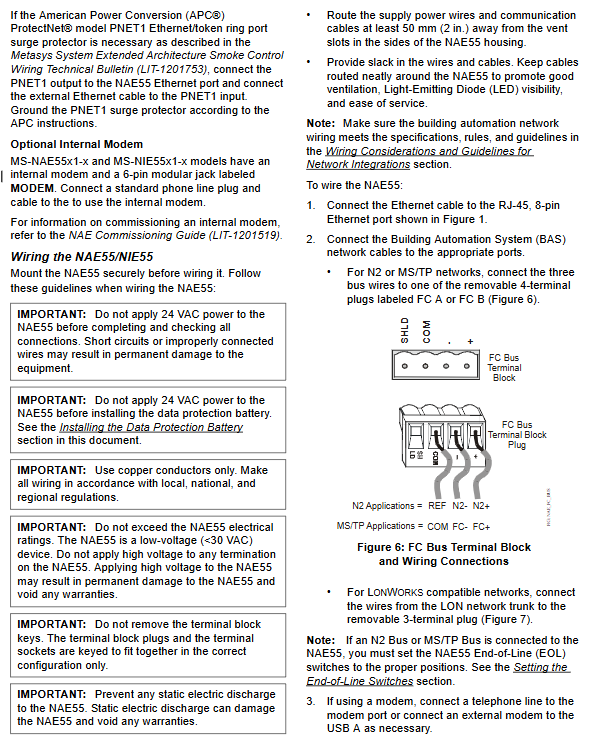
Before wiring, a data protection battery must be installed (see "Settings and Adjustments" section), and a 24VAC power supply must not be connected.
Only copper conductors are used, and wiring must comply with local, national, and regional regulations.
Do not exceed the electrical rating of the equipment (NAE55 is a low-voltage equipment,<30VAC), and do not connect to high voltage (otherwise the equipment will be damaged and the warranty will be invalidated).
The terminal block key must not be removed, and the terminal plug and socket are designed to be foolproof and can only be correctly connected.
Prevent electrostatic discharge (avoid damaging equipment and void warranty).
The power cord and communication cable should be kept at least 50 millimeters (2 inches) away from the ventilation duct on the side of the equipment.
Reserve a certain degree of slack in the cables, and arrange the wiring neatly to ensure ventilation, LED visibility, and maintenance convenience.
Core wiring steps
Ethernet connection: Insert the Ethernet cable into an 8-pin RJ-45 Ethernet port (supporting 10/100 Mbps).
Building Automation System (BAS) Network Connection:
N2 or MS/TP network: Connect three bus lines to a 4-terminal plug labeled FC A or FC B (Figure 6).
LONWorks compatible network: Connect the bus line to a 3-terminal plug (Figure 7), and there is no polarity requirement for the network wiring.
Note: The N2 and BACnet MS/TP bus protocols are different and cannot be connected to the same FC bus port; If connecting to N2 or MS/TP bus, an End of Life (EOL) switch needs to be set up (see "Settings and Adjustments" section).
Modem connection: If needed, connect the phone line to the MODEM port (built-in modem model), or connect an external modem to the USB A port.
RS-232 serial port connection (if required): Use a 9-pin male to male null modem cable to directly connect to a computer, only for point-to-point protocol (PPP) network connection (Serial A port) or obtaining an IP address (Serial B port).
Power connection: Connect the power cord of the 24VAC transformer to the power terminal block (Figure 8) to ensure that the transformer phases of all network devices are consistent (reducing interference and grounding loop issues).
Different network topology wiring specifications
Core limitations and requirements for network types
The N2 network supports 100 devices on a single bus, with a maximum cable length of 1500 meters without repeaters; Recommended 1.5mm ² (18 AWG) 3-core wire,+/- bus must be twisted pair
BACnet MS/TP network supports 100 devices on a single FC bus, with a cable length of 1500 meters without repeaters; Recommended 0.6mm (22 AWG) 3-core shielded twisted pair cable
Ethernet network star topology (requiring network hub/switch), with a maximum of 100 devices connected to a single site
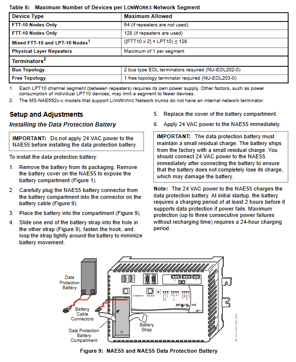
LONWorks network bus topology stub cable with a maximum length of 3 meters; FTT-10 nodes can have a maximum of 64 (without repeaters) or 128 (with repeaters); Install corresponding terminators according to topology type
Settings and Adjustments
Install data protection battery
Remove the battery and open the battery compartment cover on the device (Figure 1).
Connect the connector of the battery cable to the connector inside the battery compartment.
Place the battery in the compartment and secure it with a battery strap (pass through the hole and fasten to reduce movement).
Cover the cabin and immediately connect the 24VAC power supply (to avoid battery depletion and damage).
Attention: The battery can only provide data protection in the event of a power outage after at least 2 hours of initial charging. Full charging (24 hours) can support three consecutive power outages for protection; The battery model is MS-BAT1010-0, with a service life of 3-5 years (at 21 ° C).
Set End Connection (EOL) switch
The devices at both ends of the FC bus section need to be set as network termination devices, and each FC port of NAE55 corresponds to a set of EOL switches:
If NAE55 is an FC bus termination device, set both sets of EOL switches for the corresponding ports to the ON position (default factory ON).
If it is not a terminating device, turn the switch to positions 1 and 2.
Startup and shutdown operations
boot process
Confirm that all wiring is correct and the battery is installed.
Connect the 24VAC power supply, and the device will take up to 5 minutes to start.
Startup completion indicator: The green RUN LED is constantly on, and the red GEN FAULT LED is off.
LED test sequence at startup
After the power is turned on, the PEER COM, RUN, GENL FAULT LEDs (NAE55 also includes FC A, FC B) light up, indicating that the operating system is started.
The above LED is off and the RUN LED is flashing, indicating that the device software is loading.
The LED displays the running status of the device, and if the RUN LED is constantly on, it indicates that the device is ready.
Shutdown process
Disconnect the 24VAC power supply (unplug the power terminal block plug).
The device is powered by a data protection battery and continues to operate for 1-8 minutes (backup volatile data) until the POWER LED goes out.
If the power outage exceeds 48 hours, the data protection battery should be removed after the POWER LED is turned off (to avoid battery depletion and damage).
System restart switch
The System Re Boot switch (Figure 1) can only be pressed when the device is unresponsive and cannot be accessed through the user's device. Restarting will lose the data saved last time (including alarm, trend, and audit tracking data), and other troubleshooting methods should be attempted first.
Troubleshooting
LED status indication (core reference)
Meaning and handling suggestions for abnormal LED names in normal states
POWER (green) constantly on and off indicates that the device is turned off; Always on indicates power supply from battery or 24VAC
ETHENET (green) flashing off indicates no Ethernet traffic, possibly due to network failure or poor connection
FC A/FC B (green) flashing constantly indicates that the port has defined a controller but there is no communication; Extinguish indicates no controller definition (NIE55 does not have this port)
BATT FAULT (red) is off and constantly on, indicating a battery fault (not connected, unable to charge). If it still lights up after 48 hours, check the connection or replace the battery
GENL FAULT (red) off and constantly on indicates general faults (such as high CPU/memory usage, high temperature, battery failure, etc.)
Common problem handling
Battery failure: Check the battery connection. If the connection is normal but still reports an error, replace the MS-BAT1010-0 model battery.
Communication failure: Confirm that the cable connection is correct, the topology meets specifications, the EOL switch setting is correct, and stay away from electromagnetic interference sources.
High temperature: Check the equipment combination inside the casing to ensure that there are no excessive heating devices and good ventilation.
Technical specifications and ordering information
Core technical parameters
Power requirements: Dedicated 24VAC power supply (North American Class 2, European SELV), 50/60Hz, input voltage 20-30VAC
Maximum power consumption of 50 VA
Working environment 0-50 ° C (32-122 ° F), 10-90% RH (dew point ≤ 30 ° C)
Storage environment -40-70 ° C (-40-158 ° F), ≤ 95% RH (dew point ≤ 30 ° C)
Processor MS-NAE5510-0U/NIE5510-0U uses 300MHz Geode GX1; Other models use 400MHz Geode GX533
512MB Flash non-volatile memory, 256MB DRAM
Dimensions (height x width x depth) 226 x 332 x 96.5mm (8.9 x 13.1 x 3.8 inches)
Protection level IP20 (IEC 60529)
Product and accessory ordering
Core product models (partial)
Product code description
MS-NAE5510-1 supports 2 N2 or BACnet MS/TP buses
MS-NAE5510-0U UL 864 8th edition certification, suitable for smoke control
MS-NAE5520-1 supports 1 LONWorks bus and 2 N2/MS/TP buses
MS-NAETUNL-8 N2 Tunnel Function Enabling Tool
Key components
Product code description
MS-BAT1010-0 Data Protection Battery (Replacement)
AS-XFR100-1 24VAC power transformer (with casing)
MS-SECVT-0 Serial to Ethernet Converter (N2 Tunnel Application)
Note: Add "G" after the product code for the US version, "E" for the European version, and "-701" for repair parts.
Maintenance and Compliance Information
Equipment replacement and registration
After replacing the NAE or adding new devices, it is necessary to update the site registration to ensure that the devices are recognized and communicate properly (refer to the NAE Debugging Guide LIT-1201519).
Compliance certification
United States: UL 916 certification, FCC Part 15 Class A, UL 864 smoke control certification (specific models).
Europe: CE mark, compliant with EMC Directive 89/336/EEC.
Australia/New Zealand: C-Tick logo.
International: BACnet BTL 135-2004 certification (B-BC level).
- YOKOGAWA
- Reliance
- ADVANCED
- SEW
- ProSoft
- WATLOW
- Kongsberg
- FANUC
- VSD
- DCS
- PLC
- man-machine
- Covid-19
- Energy and Gender
- Energy Access
- Renewable Integration
- Energy Subsidies
- Energy and Water
- Net zero emission
- Energy Security
- Critical Minerals
- A-B
- petroleum
- Mine scale
- Sewage treatment
- cement
- architecture
- Industrial information
- New energy
- Automobile market
- electricity
- Construction site
- HIMA
- ABB
- Rockwell
- Schneider Modicon
- Siemens
- xYCOM
- Yaskawa
- Woodward
- BOSCH Rexroth
- MOOG
- General Electric
- American NI
- Rolls-Royce
- CTI
- Honeywell
- EMERSON
- MAN
- GE
- TRICONEX
- Control Wave
- ALSTOM
- AMAT
- STUDER
- KONGSBERG
- MOTOROLA
- DANAHER MOTION
- Bentley
- Galil
- EATON
- MOLEX
- Triconex
- DEIF
- B&W
- ZYGO
- Aerotech
- DANFOSS
- KOLLMORGEN
- Beijer
- Endress+Hauser
- schneider
- Foxboro
- KB
- REXROTH
- YAMAHA
- Johnson
- Westinghouse
- WAGO
- TOSHIBA
- TEKTRONIX
- BENDER
- BMCM
- SMC
- HITACHI
- HIRSCHMANN
- XP POWER
- Baldor
- Meggitt
- SHINKAWA
- Other Brands
- UniOP
- KUKA
- IBA
- Beckhoff
-
LTI SC52.0040.0012.0000.0 - Servo Drive
-
Lti SC52.0040.0012.0000.0 - Servo Drive
-
Milton Industries LTI Tool By Milton LT1240 - 1/2" Drive Lugnut Remover
-
LTi Drives SO84.200.P030.0000.0-W - Servo Spindle Drive
-
LTI DRIVES LSP08-035-320-30-B0R1PY170 - Servo Motor
-
LTI DRIVES SE84.200.SC00.0001.0-W - Servo Drive
-
Lust CDE34.005.W2.2 - Lti Drives Controller
-
LTi SO84.012.0030.0011.2 - ServoOne Servo Drive
-
LTi Drives SO CM-P.0010.11.00.0 - Servo Drive Controller
-
LTi CDE34.017.W3.0 - Servo Drive
-
LTI Drives CDB32.004, C2.0,SH - Positioning Controller
-
LUST CM-CAN1 - LTi DRIVES Communication Module
-
LTi SO84.012.1030.0000.2 - Servo Drive
-
LTI MOOG CDE54.044 - PITCHMASTER FREQUENCY CONVERTER 181-01019
-
MOOG LTI 181-01019 CDE54.044 - PITCHMASTER FREQUENCY CONVERTER
-
Lust LTi Drives CDE34.010,D2.0 - Servo Drive Controller
-
LTI SO84.032.0003.0101.2 - Servo Drive
-
Seagate 9CC132-302 Harris LTI-CS IRT-34-0021-01 - Hard Drive 160GB
-
LTI SO84.032.0003.0001.2 - Servo Drive
-
LTI SO24.007.0070.0000.1 - SERVO CONTROLLER
-
LTi drive CDA32.003.C3.0.H05-01.PC1 - Servo Drive
-
LTI SO84.016.0030.0000.2 - SERVO CONTROLLER
-
LUST LTI CD A34.008,W1.4, BR - SERVO DRIVE
-
MOOG LTI 181-01019 CDE54.044 - PITCHMASTER FREQUENCY CONVERTER
-
LTI MOOG 181-01019 - PITCH Master Servo Drive CDE54.044
-
LTI SERVO ONE SO84.045.0030.0001.2-W - Drive
-
LUST LTi SO84.032.0040.0000.2 - SERVO ONE DRIVE
-
LTi Drives LSH-074-2-30-3 20/T1,G6.1M - SERVO MOTOR
-
LTI SO84.016.0000.0101.2 - servo drive
-
LTI SA54.0550.0033.0000.0 - Servo Drive
-
LTI SA54.0550.0033.0000.0 - Servo Drive
-
LTI LT 4850 - 3/8" Drive 3-Pc Twist Socket Transmission Drain Plug Removal System
-
LTI Tools LT4400-30 Lock Technology - 3/4" Twist Socket 1/2" Drive Lugnut Remover
-
LTI Tools LT-1400C - 1/2 Drive Wheel Torque Extension Tool
-
LTI Tools LT1250 - 1/2" Drive Dual Sided Socket Lug Nut Remover Tool
-
LTI SO84.032.0003.0101.2 - Servo Drive
-
LTI MOOG 181-01019 - PITCH Master Servo Drive CDE54.044
-
MOOG LTI 181-01019 CDE54.044 - PITCHMASTER FREQUENCY CONVERTER
-
MOOG LTI 181-01019 CDE54.044 - PITCHMASTER FREQUENCY CONVERTER
-
MOOG LTI 181-01019 CDE54.044 - PITCHMASTER FREQUENCY CONVERTER
-
LTI SA54.0550.0033.0000.0 - Servo Drive
-
LTI Tools LT-4800 - 7 Piece Twist Socket 3/8" Drive Oil Drain Plug Removal Set
-
LTI SA54.0550.0033.0000.0 - Servo Drive
-
LTI Drive SO24.007.00300000.0 - Servo Drive
-
LTI TOOLS LTI 1400-I - Drive Wheel Torque Extension
-
LTI Tools LT4400-3 - 3/4" 19mm Twist Socket 1/2" Drive Lugnut
-
LTI TOOLS LTI 1400-BB - Drive Wheel Torque Extension
-
LTI SO84.032.0003.0101.2 - Servo Drive
-
LTI Tools LT-4512 - 3/8" Drive 12mm Twist Socket
-
LTI MOTION Luster SO84.032.0003.0001.2 - Servo Drive
-
LTI Tool By Milton LT1600P - 1" Drive Torx Stick
-
LTI Lust VF1424L,HF,OP2,S56 - Variable Frequency Drive
-
LUST CDA32.004,C1.4,H08,B0 - SERVO DFRIVE CM-CAN1 Module
-
LTI SO84.045.0002.0001.2-W - Drive
-
LTI Lust VF1404M,C9,PT1,BR1 - Inverter Type VF1404M
-
LTI SA54.0550.0033.0000.0 - Servo Drive
-
LTI Tools LT-1400C - 1/2" Drive Wheel Torque Extension
-
Lust LTI DRiVES CDA32.006, C3.0, H09 - Variateur De Fr茅quence Frequency Inverter
-
LTI MOOG CDE54.044 - PITCH master SERVO DRIVE
-
LTI MOOG CDE54.044 - PITCH master SERVO DRIVE
-
LTI SO84.143.0020.0101.2-W - servo drive
-
LTI MOTION SC34.0200.0011.0000.0 - Servo drives
-
LTI SO84.032.0003.0001.2 - Servo Drive
-
LTI DRIVES GmbH MS100 - Assembly Set Mounting Kit
-
LTI SO84.032.0003.0001.2 - Servo Drive
-
LTI SO84.032.0003.0001.2 - Servo Drive
-
LTI MOTION SO84.032.0003.0101.2 - servo drive
-
LTI SO84.032.0003.0101.2 - Servo Drive
-
LTI MOOG CDE54.044 - PITCH master SERVO DRIVE
-
LTI MOTION CDE32.004.C2.4 - Servo drives
-
LTI CDD34.032锛學x.x锛孊R锛孭C1 - Servo Drive
-
Lust LTI DRiVES CDA32.006, C3.0, H09 - Inversor De Frecuencia Frequency Inverter
-
Lust SO84.008.0030.1000.0 - Servo One LTi Drive
-
LTI MOTION SO84.032.0003.0101.2 - Servo drives
-
LUST LTi CDA32.004,C1.4 - SERVO DRIVE
-
LTI MOOG CDE54.044 - PITCH Master SERVO DRIVE
-
LTI KEBA CDB32.004 C2.7, SH - PN: 08673530 Frequency Inverter
-
LTI Tools LT-1400C - 1/2" Drive Wheel Torque Extension
-
LTI LT1400-E - 1/2" Drive Wheel Torque Extension
-
LTI MOOG 181-01019 - PITCH master SERVO DRIVE CDE54.044
-
LTI LSN-097-0510-30-560/T1 - Actuator Motor
-
LTI Tools LT 4800 - 7 Piece 3/8" Drive Twist Socket Oil Drain Plug Removal System
-
LTI DRIVES GmbH MS100 - MONTAGESET Assembly Set Mounting Kit
-
Lti SC52.0040.0012.0000.0 - Servo Drive
-
LTI DRIVES GmbH MS100 - Juego De Montaje Assembly Set Mounting Kit
-
LTi DSM4-14.2-21R83-200 - Drives servomoteur Servo Motor
-
MOOG CDE 54.044.GDA - Pitch Master Industrielle Turbine Lti Drive
-
LTI SO24.004.0030.1000.0 - Servo Drive Controller
-
Lti MOOG CDE54.044 - Pitch Master Servo Drive
-
Lust LTI DRiVES CDA32.006, C3.0, H09 - Inverter
-
LTI MOTION GMBH CDB34.006,W3.0,PC1,H39 - Frequency inverter
-
LTI SO84.032.0003.0001.2 - Servo Drive
-
MOOG CDE 54.044.D - Pitch Master Industrielle Turbine Lti Drive
-
LTI TOOLS LT-1460 - 1/2" DRIVE WHEEL TORQUE EXTENSION KIT 5 PIECE SET
-
Lust Cdb32.003, C2.4 - Lti Drives Servoregulador Frecuencia Servo Controller Inverter
-
Lust LTI DRIVES CDA32.006, C3.0, H09 - Frequency Inverter
-
Lust Lti SO82.004.0030.0000.2 - Servo Drive
-
LTI MOTION SC34.0200.0011.0000.0-SL - Servo drives
-
LTI MOTION SA54.0075.0033.0000.0 - Servo drives
-
LTI MOTION SC32.0075.1011.0000.0 - Servo drives
-
Lust Cdb32.003, C2.4 - Lti Drives Servo Controller Frequency Inverter
-
LTI MOOG CDE54.044 - PITCH master SERVO DRIVE
-
Lust Lti Cde34.006,W2.0,Br - Servo Drive
-
Lust LTi MOTION CDE34.044,W2.4,H13 - Servo Drive
-
Lust LTi Drives Cde32.008, W2.2.br - Positionierregler Posici贸n Mando Positioning Controller
-
LTI MOOG CDE54.044 - PITCH master SERVO DRIVE
-
LUST Antriebstechnik B-DS 125.1 - LTi DRiVES Accessories Drive Component
-
LTi LSMM13-100-4N-001 - servo motor
-
Lti CDA32.004 C1.4, H08, B0 - PN: 3084456 Frequency Inverter
-
LTI MOTION CDE34.006.WXX.PC1 - Servo drives
-
LTI MOTION SO24.007.0030.1000.0 - Servo drives
-
Lust CDD34.005.C2.1 - LTI Drive
-
Lti SC52.0040.0012.0000.0 - Servo Drive
-
LTI Tools LT4400-30 - 1/2" Drive 19mm 3/4" Twist Socket
-
Lust LTi Drives Cde32.008, W2.2.br - Positionierregler Posici贸n Mando Positioning Controller
-
LTI MOOG CDE54.044 - PITCH master SERVO DRIVE
-
LUST Antriebstechnik B-DS 125.1 - LTi DRiVES Accessories Drive Component
-
LTI DRIVES GmbH MS100 - MONTAGESET Assembly Set Mounting Kit
-
Lust LTi SO84.032.0043.0000.2 - Servo one Drive
-
LUST LTi Drives CM-CAN1 - Modulo Di Comunicazione Communication Module
-
LTI drive CDF 30.008.C3.6 - Servo Drive
-
LTI MOOG 181-01019 - PITCH master SERVO DRIVE
-
LTI CDB34.014,W2.4,BR,SH - Servo Driver
-
Lti SC52.0040.0012.0000.0 - Servo Drive
-
LTi Drive CDF30.002 - Power Supply Fuse
-
LTI Tools LT-4621-D - Deep Well Twist Socket 3/8" Drive 1/2"
-
LTI MOOG PITCH master CDE54.044 - SERVO DRIVE Frequency Converter
-
LTI SO84.076.S030.0001.2-W - Servo One Drive

K-JIANG

Add: Jimei North Road, Jimei District, Xiamen, Fujian, China
Tell:+86-15305925923