
K-WANG


Watlow Series 96 Temperature Controller
Watlow Series 96 Temperature Controller
Product Core Overview
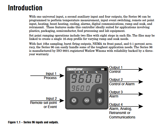
The Watlow Series 96 is a 1/16 DIN sized microprocessor based temperature controller with universal input, multi output configuration, and flexible control capabilities, designed specifically for scenarios such as plastic processing, packaging, semiconductors, food processing, and laboratory equipment. The product has high stability and multifunctional scalability as its core advantages, supporting single/dual PID control, curve programming (Ramp/Soak), remote set point retransmission and other functions. Combined with NEMA 4X front panel protection and 0.1% measurement accuracy, it can meet the precise temperature control requirements of harsh industrial environments.
Core features:
Input/output flexibility: 1 universal input (compatible with thermocouples, RTDs, process signals), 1 auxiliary input (event/remote set point), 4 configurable outputs (relay/SSR/switch DC/process retransmission), suitable for multiple types of sensors and actuators.
Control capability: Supports On Off, P, PI, PID control modes, built-in Auto tune and Burst Fire functions, curve programming supports 2 files, 8 steps per file, and can be linked and extended to 16 step continuous curves.
Convenient operation: The patented Custom Menu can add 16 commonly used parameters, dual 4-digit LED display, support ° C/° F/process unit switching, intuitive button operation, and can be quickly mastered by both new and expert users.
Communication and Expansion: Optional EIA/TIA-232/485 communication (Modbus RTU protocol), supports remote configuration and data retransmission, and some models have event input triggering functions (such as start/pause curves, reset alarms).
Product model and core configuration
(1) Model coding rules
The model consists of 12 characters, and the key dimensions are defined as follows. The complete model format is 96 [power] [input 2] [output 1] [output 2] [output 3] [output 4] [software/display]:
Encoding position meaning optional configuration
Power supply (3rd position) Power supply type A=100-240V AC/DC, B=24-28V AC/DC
Input 2 (4th digit) Auxiliary input function 0=None, 1=Event input+Remote set point (0-5V/4-20mA)
Output 1-4 (bits 5-8) Output type C=switch DC/open collector, D=electromechanical relay (2A), F=process output (0-10V/4-20mA), K=SSR (0.5A), A=none
Software/Display (bits 9-12) Function and Display 00=Standard Software, AA=Curve Programming Software; RR/RG/GR/GG=red/green dual display combination
(2) Core hardware specifications
Category detailed parameters
Input Characteristics - General Input: Thermocouples (J/K/T/N/E/R/S/B, etc.), RTDs (2/3-wire 100 Ω platinum resistors), process signals (0-10V/4-20mA, etc.).
-Input accuracy: ± 0.1% range ± 1 ° C (standard conditions), sampling rate 10Hz (single input)/5Hz (dual input).
-Auxiliary input: Event input supports dry contact or 3-36V DC voltage, remote set point supports 4-20mA/0-10V signal.
Output capability - Relay output: Form C contact, 2A@250V AC/30V DC, The mechanical lifespan is 100000 cycles.
-SSR/DC switch: SSR output 0.5A@20-280V AC, Switch DC maximum 200mA@42V DC。
-Process output: 0-10V (minimum 1k Ω load) or 4-20mA (maximum 800 Ω load), accuracy ± 15mV/± 30 μ A.
Environment and Protection - Operating Temperature: 0-65 ° C (non condensing), Relative Humidity: 0-90% (non condensing).
-Protection level: front panel NEMA 4X, enclosure IP4X.
-Power consumption: Maximum 7VA, supports power-off data storage (non-volatile memory).
Installation and wiring specifications
(1) Installation requirements
Panel opening and fixing
Hole size: 52mm × 52mm (2.05in × 2.05in), panel thickness 1.5-9.7mm (0.06-0.38in).
Installation steps: Confirm that the front panel sealing ring is in place → Insert the controller from the front of the panel → Install the fixing ring and buckle → Tighten the screws (with a maximum gap of 0.025 inches) to ensure a leak proof seal.
Attention: Avoid excessive tightening of screws that may cause damage to the panel. When installing multiple units in parallel, a heat dissipation distance of ≥ 30mm should be reserved and kept away from corrosive gases and strong vibration environments.
Power supply and wiring safety
Power wiring: For high-power models (A), connect L1/L2 terminals (100-240V AC/DC), and for low-power models (B), connect+/- terminals (24-28V AC/DC), matching the power type indicated on the model label.
Wiring specification: Wire specification 12-22 AWG, terminal torque 5.0 in lb, analog input and power/digital signals need to be isolated and wired to avoid ground loop interference.
Safety compliance: Following NEC wiring standards, explosion-proof switches are required for hazardous environments, and sensor wiring must match the type (thermocouple extension wire material is consistent, 3-wire RTD lead resistance is balanced).
(2) Key wiring example
Sensor wiring
Thermocouple: The negative electrode (usually red) should be connected to the S1 terminal, and the extension wire should match the thermocouple material (such as K-type wire) to avoid errors caused by mixing.
When wiring RTD with a 3-wire system, the resistance of the three leads should be consistent (≤ 20 Ω), and S1 should be connected to a white lead to compensate for the effect of lead resistance through wiring.
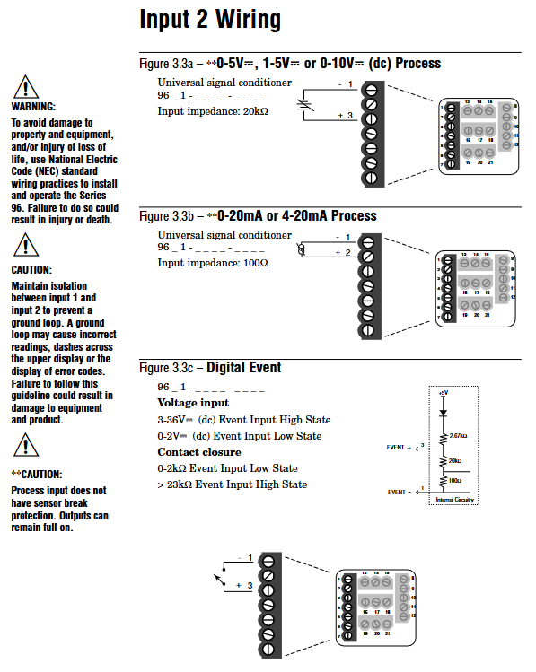
Process signal: 4-20mA signal connected to+R1/- S1 terminal (input impedance of 100 Ω), 0-10V signal connected to+T1/- S1 terminal (input impedance of 20k Ω), requiring separate shielded wiring.
Output and communication wiring
Relay output (D-type): When connecting to an AC load, an RC suppressor (Watlow model 0804-0147-0000) should be connected in series to avoid arcing damage to the contacts due to power failure of inductive loads.
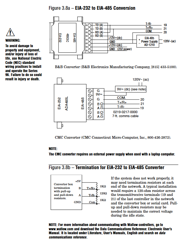
Communication wiring: EIA-485 uses twisted pair cables, with T+/R+connected to terminal B and T -/R - connected to terminal A. A 120 Ω terminal resistor needs to be added at the end of the bus, and it can support up to 32 devices in a network (with extension relays up to 247).
Event input: The dry contact is connected to the EVENT+/- terminal, with an active state resistance of<2k Ω and an inactive state resistance of>23k Ω. The voltage input supports 3-36V DC, with an active state resistance of>3V and an inactive state resistance of<2V.
Operating interface and core functions
(1) User interface
Keys and Display
Key functions: up/down arrow keys (parameter adjustment/menu scrolling), forward key (confirm/enter submenu), infinite key (return to home page/start/pause curve).
Display mode: The process value/error code is displayed on the upper screen, and the set value/parameter name is displayed on the lower screen. The indicator lights include output activation (1-4), manual mode (%), and profile mode.
Custom menu: Press and hold the forward key+infinite key for 6 seconds to enter the factory page, where you can add commonly used parameters (such as set points, PID parameters, alarm thresholds), up to 16 items, for quick access without the need for layer by layer navigation.
Menu Structure
Home Page: Display process values and set points, allowing for direct adjustment of commonly used parameters.
Operations page: including monitoring, users PID1/2、 Alarm menu, configurable control mode, automatic setting, alarm threshold.
Setup page: Configure input types, output functions, global parameters (units, fault modes, etc.).
Factory page: Customize menu, lock, diagnostic, calibration functions (permission required).
(2) Core function operation
PID control and automatic tuning
Automatic tuning: Enter "Operations - Auto tune" and select "tune". The controller aims to achieve 90% of the current set point and calculates the optimal PID parameters by crossing the target value multiple times. During the tuning period, it outputs 100% power and ensures load safety.
Control mode switching: On Off control (proportional band set to 0), PI/PID control (adjusting proportional band/integral/derivative parameters), in dual PID mode, output 1 corresponds to heating, output 2 corresponds to cooling, and a dead zone can be set to avoid antagonism.
Burst Fire: Suitable for resistive loads, reduces electromagnetic interference (RFI) through zero crossing switching, requires the "Burst" function to be enabled in the PID menu, with a cycle time of 0.1-60 seconds.
Curve Programming (Ramp/Soak)
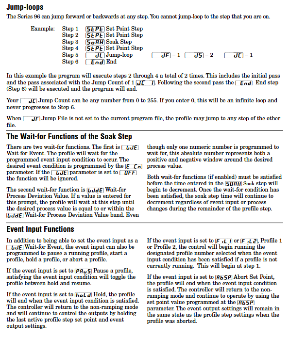
Curve configuration: Supports 2 files (File1/File2), with 8 steps per file. The step types include Set Point, Soak, Jump Loop, and End. Event output can be set (such as starting an external device).
Operation: Press the infinite key from the homepage to enter the pre run menu, select the file and start steps, and then press the infinite key to start; Press the infinite key to pause during operation, and the pause step can be restored through the "resU" parameter.
Waiting function: The insulation step supports "Wait for Event" (event input trigger) and "Wait for Deviation" (process value entering deviation zone trigger), and timing can only start after meeting the conditions.
Alarm and fault handling
Alarm configuration: 4-channel alarms can be set as process alarms (fixed threshold) or deviation alarms (relative to the set point), supporting high/low alarms, locking/non locking, and mute functions. Hysteresis can be set to 1-9999 units to avoid false triggering.
Fault diagnosis: Input error (sensor open circuit/over range), system error (RAM/ROM fault), open-loop detection (100% output without process value change), locate the problem through the error code on the display screen (such as Err1-Err16), refer to the appendix for troubleshooting.
Fault mode: When the sensor fails, it can be set to Bumpless, Manual mode, or Off output mode. Bumpless switching can maintain the output power before the fault and avoid process fluctuations.
Communication and Remote Configuration
(1) Communication parameter settings
Protocol and hardware: Supports Modbus RTU protocol, optional EIA-232 (model including "R") or EIA-485 (model including "U") communication module, wiring needs to distinguish T+/R+/T -/R-terminals.
Configuration steps: Enter "Setup - Output4- Baud Rate" to set the baud rate (1200/2400/4800/9600/19200), and set the device address (1-247) in "Address" to ensure consistency with the parameters of the upper computer (PLC/PC).
Data retransmission: Output 4 can be configured as a retransmission function (model includes "M"), supporting retransmission process values, setpoints, or output power. The signal range is calibrated through "Scale Low/High" and "Range Low/High" (such as 4-20mA corresponding to 0-100 ° C).
(2) Remote operation example
The upper computer reads the process value (register 100), set point (register 300), and alarm status (register 106) through Modbus.
Remote start curve: By writing the Modbus command register (40001=1 to start File140002=1 to start Step1).
Remote parameter modification: Write the set point to register 300 and write the PID parameter to the corresponding register (such as proportional band 500), ensuring communication write permission (non-volatile memory disable requires closing register 24).
Maintenance and troubleshooting
(1) Daily maintenance
Regular inspection: Clean the sealing ring and heat dissipation area of the front panel on a monthly basis, tighten the terminals quarterly (to avoid cold flow loosening), and calibrate the input/output annually (through the "Factory Calibration" menu, a standard signal source is required).
Parameter backup: Save commonly used parameter configurations or record key parameters (input type, PID parameters, alarm thresholds) through the "Factory Custom Menu" to avoid reconfiguration after faults.
Calibration process: Input calibration requires providing high and low point standard signals (such as thermocouple 0mV/50mV), calculating the correction value through "Electrical Input Slope/Offset", and outputting calibration in the same way (such as 4-20mA signal calibration).
(2) Common fault handling
Possible causes and solutions for the fault phenomenon
No display/output power supply not connected, fuse burned out, safety interlock activated. Check the power supply voltage and fuse (Slot C terminal 98/99), confirm the interlock switch status, and re tighten the power supply wiring
The process value deviation is large. The sensor wiring is incorrect, the calibration offset is not set, and the input type does not match. Check the sensor wiring (thermocouple positive and negative poles/RTD leads), adjust the "Calibration Offset", and confirm that the "Input Type" is consistent with the sensor
Communication failure: baud rate/address mismatch, reversed wiring, no terminal resistor added. Unify device communication parameters, check the correspondence between T+/R+and A/B terminals, and add a 120 Ω resistor at the end of the bus
The alarm cannot be cleared. The alarm condition has not been lifted and the alarm lockout confirmation process value has returned to the safe range (including the hysteresis area). Press the infinite key to clear the lockout alarm and check the "Latching" parameter setting
The curve cannot be started and has not entered the pre run mode. The step type configuration is incorrect. Press the infinite key to enter the pre run menu, select the file and step, and confirm that there is no "Jump" loop error in the curve step (such as jumping to the current step)
- YOKOGAWA
- Reliance
- ADVANCED
- SEW
- ProSoft
- WATLOW
- Kongsberg
- FANUC
- VSD
- DCS
- PLC
- man-machine
- Covid-19
- Energy and Gender
- Energy Access
- Renewable Integration
- Energy Subsidies
- Energy and Water
- Net zero emission
- Energy Security
- Critical Minerals
- A-B
- petroleum
- Mine scale
- Sewage treatment
- cement
- architecture
- Industrial information
- New energy
- Automobile market
- electricity
- Construction site
- HIMA
- ABB
- Rockwell
- Schneider Modicon
- Siemens
- xYCOM
- Yaskawa
- Woodward
- BOSCH Rexroth
- MOOG
- General Electric
- American NI
- Rolls-Royce
- CTI
- Honeywell
- EMERSON
- MAN
- GE
- TRICONEX
- Control Wave
- ALSTOM
- AMAT
- STUDER
- KONGSBERG
- MOTOROLA
- DANAHER MOTION
- Bentley
- Galil
- EATON
- MOLEX
- Triconex
- DEIF
- B&W
- ZYGO
- Aerotech
- DANFOSS
- KOLLMORGEN
- Beijer
- Endress+Hauser
- schneider
- Foxboro
- KB
- REXROTH
- YAMAHA
- Johnson
- Westinghouse
- WAGO
- TOSHIBA
- TEKTRONIX
- BENDER
- BMCM
- SMC
- HITACHI
- HIRSCHMANN
- XP POWER
- Baldor
- Meggitt
- SHINKAWA
- Other Brands
- UniOP
- KUKA
- IBA
- Beckhoff
-
LTI SC52.0040.0012.0000.0 - Servo Drive
-
Lti SC52.0040.0012.0000.0 - Servo Drive
-
Milton Industries LTI Tool By Milton LT1240 - 1/2" Drive Lugnut Remover
-
LTi Drives SO84.200.P030.0000.0-W - Servo Spindle Drive
-
LTI DRIVES LSP08-035-320-30-B0R1PY170 - Servo Motor
-
LTI DRIVES SE84.200.SC00.0001.0-W - Servo Drive
-
Lust CDE34.005.W2.2 - Lti Drives Controller
-
LTi SO84.012.0030.0011.2 - ServoOne Servo Drive
-
LTi Drives SO CM-P.0010.11.00.0 - Servo Drive Controller
-
LTi CDE34.017.W3.0 - Servo Drive
-
LTI Drives CDB32.004, C2.0,SH - Positioning Controller
-
LUST CM-CAN1 - LTi DRIVES Communication Module
-
LTi SO84.012.1030.0000.2 - Servo Drive
-
LTI MOOG CDE54.044 - PITCHMASTER FREQUENCY CONVERTER 181-01019
-
MOOG LTI 181-01019 CDE54.044 - PITCHMASTER FREQUENCY CONVERTER
-
Lust LTi Drives CDE34.010,D2.0 - Servo Drive Controller
-
LTI SO84.032.0003.0101.2 - Servo Drive
-
Seagate 9CC132-302 Harris LTI-CS IRT-34-0021-01 - Hard Drive 160GB
-
LTI SO84.032.0003.0001.2 - Servo Drive
-
LTI SO24.007.0070.0000.1 - SERVO CONTROLLER
-
LTi drive CDA32.003.C3.0.H05-01.PC1 - Servo Drive
-
LTI SO84.016.0030.0000.2 - SERVO CONTROLLER
-
LUST LTI CD A34.008,W1.4, BR - SERVO DRIVE
-
MOOG LTI 181-01019 CDE54.044 - PITCHMASTER FREQUENCY CONVERTER
-
LTI MOOG 181-01019 - PITCH Master Servo Drive CDE54.044
-
LTI SERVO ONE SO84.045.0030.0001.2-W - Drive
-
LUST LTi SO84.032.0040.0000.2 - SERVO ONE DRIVE
-
LTi Drives LSH-074-2-30-3 20/T1,G6.1M - SERVO MOTOR
-
LTI SO84.016.0000.0101.2 - servo drive
-
LTI SA54.0550.0033.0000.0 - Servo Drive
-
LTI SA54.0550.0033.0000.0 - Servo Drive
-
LTI LT 4850 - 3/8" Drive 3-Pc Twist Socket Transmission Drain Plug Removal System
-
LTI Tools LT4400-30 Lock Technology - 3/4" Twist Socket 1/2" Drive Lugnut Remover
-
LTI Tools LT-1400C - 1/2 Drive Wheel Torque Extension Tool
-
LTI Tools LT1250 - 1/2" Drive Dual Sided Socket Lug Nut Remover Tool
-
LTI SO84.032.0003.0101.2 - Servo Drive
-
LTI MOOG 181-01019 - PITCH Master Servo Drive CDE54.044
-
MOOG LTI 181-01019 CDE54.044 - PITCHMASTER FREQUENCY CONVERTER
-
MOOG LTI 181-01019 CDE54.044 - PITCHMASTER FREQUENCY CONVERTER
-
MOOG LTI 181-01019 CDE54.044 - PITCHMASTER FREQUENCY CONVERTER
-
LTI SA54.0550.0033.0000.0 - Servo Drive
-
LTI Tools LT-4800 - 7 Piece Twist Socket 3/8" Drive Oil Drain Plug Removal Set
-
LTI SA54.0550.0033.0000.0 - Servo Drive
-
LTI Drive SO24.007.00300000.0 - Servo Drive
-
LTI TOOLS LTI 1400-I - Drive Wheel Torque Extension
-
LTI Tools LT4400-3 - 3/4" 19mm Twist Socket 1/2" Drive Lugnut
-
LTI TOOLS LTI 1400-BB - Drive Wheel Torque Extension
-
LTI SO84.032.0003.0101.2 - Servo Drive
-
LTI Tools LT-4512 - 3/8" Drive 12mm Twist Socket
-
LTI MOTION Luster SO84.032.0003.0001.2 - Servo Drive
-
LTI Tool By Milton LT1600P - 1" Drive Torx Stick
-
LTI Lust VF1424L,HF,OP2,S56 - Variable Frequency Drive
-
LUST CDA32.004,C1.4,H08,B0 - SERVO DFRIVE CM-CAN1 Module
-
LTI SO84.045.0002.0001.2-W - Drive
-
LTI Lust VF1404M,C9,PT1,BR1 - Inverter Type VF1404M
-
LTI SA54.0550.0033.0000.0 - Servo Drive
-
LTI Tools LT-1400C - 1/2" Drive Wheel Torque Extension
-
Lust LTI DRiVES CDA32.006, C3.0, H09 - Variateur De Fr茅quence Frequency Inverter
-
LTI MOOG CDE54.044 - PITCH master SERVO DRIVE
-
LTI MOOG CDE54.044 - PITCH master SERVO DRIVE
-
LTI SO84.143.0020.0101.2-W - servo drive
-
LTI MOTION SC34.0200.0011.0000.0 - Servo drives
-
LTI SO84.032.0003.0001.2 - Servo Drive
-
LTI DRIVES GmbH MS100 - Assembly Set Mounting Kit
-
LTI SO84.032.0003.0001.2 - Servo Drive
-
LTI SO84.032.0003.0001.2 - Servo Drive
-
LTI MOTION SO84.032.0003.0101.2 - servo drive
-
LTI SO84.032.0003.0101.2 - Servo Drive
-
LTI MOOG CDE54.044 - PITCH master SERVO DRIVE
-
LTI MOTION CDE32.004.C2.4 - Servo drives
-
LTI CDD34.032锛學x.x锛孊R锛孭C1 - Servo Drive
-
Lust LTI DRiVES CDA32.006, C3.0, H09 - Inversor De Frecuencia Frequency Inverter
-
Lust SO84.008.0030.1000.0 - Servo One LTi Drive
-
LTI MOTION SO84.032.0003.0101.2 - Servo drives
-
LUST LTi CDA32.004,C1.4 - SERVO DRIVE
-
LTI MOOG CDE54.044 - PITCH Master SERVO DRIVE
-
LTI KEBA CDB32.004 C2.7, SH - PN: 08673530 Frequency Inverter
-
LTI Tools LT-1400C - 1/2" Drive Wheel Torque Extension
-
LTI LT1400-E - 1/2" Drive Wheel Torque Extension
-
LTI MOOG 181-01019 - PITCH master SERVO DRIVE CDE54.044
-
LTI LSN-097-0510-30-560/T1 - Actuator Motor
-
LTI Tools LT 4800 - 7 Piece 3/8" Drive Twist Socket Oil Drain Plug Removal System
-
LTI DRIVES GmbH MS100 - MONTAGESET Assembly Set Mounting Kit
-
Lti SC52.0040.0012.0000.0 - Servo Drive
-
LTI DRIVES GmbH MS100 - Juego De Montaje Assembly Set Mounting Kit
-
LTi DSM4-14.2-21R83-200 - Drives servomoteur Servo Motor
-
MOOG CDE 54.044.GDA - Pitch Master Industrielle Turbine Lti Drive
-
LTI SO24.004.0030.1000.0 - Servo Drive Controller
-
Lti MOOG CDE54.044 - Pitch Master Servo Drive
-
Lust LTI DRiVES CDA32.006, C3.0, H09 - Inverter
-
LTI MOTION GMBH CDB34.006,W3.0,PC1,H39 - Frequency inverter
-
LTI SO84.032.0003.0001.2 - Servo Drive
-
MOOG CDE 54.044.D - Pitch Master Industrielle Turbine Lti Drive
-
LTI TOOLS LT-1460 - 1/2" DRIVE WHEEL TORQUE EXTENSION KIT 5 PIECE SET
-
Lust Cdb32.003, C2.4 - Lti Drives Servoregulador Frecuencia Servo Controller Inverter
-
Lust LTI DRIVES CDA32.006, C3.0, H09 - Frequency Inverter
-
Lust Lti SO82.004.0030.0000.2 - Servo Drive
-
LTI MOTION SC34.0200.0011.0000.0-SL - Servo drives
-
LTI MOTION SA54.0075.0033.0000.0 - Servo drives
-
LTI MOTION SC32.0075.1011.0000.0 - Servo drives
-
Lust Cdb32.003, C2.4 - Lti Drives Servo Controller Frequency Inverter
-
LTI MOOG CDE54.044 - PITCH master SERVO DRIVE
-
Lust Lti Cde34.006,W2.0,Br - Servo Drive
-
Lust LTi MOTION CDE34.044,W2.4,H13 - Servo Drive
-
Lust LTi Drives Cde32.008, W2.2.br - Positionierregler Posici贸n Mando Positioning Controller
-
LTI MOOG CDE54.044 - PITCH master SERVO DRIVE
-
LUST Antriebstechnik B-DS 125.1 - LTi DRiVES Accessories Drive Component
-
LTi LSMM13-100-4N-001 - servo motor
-
Lti CDA32.004 C1.4, H08, B0 - PN: 3084456 Frequency Inverter
-
LTI MOTION CDE34.006.WXX.PC1 - Servo drives
-
LTI MOTION SO24.007.0030.1000.0 - Servo drives
-
Lust CDD34.005.C2.1 - LTI Drive
-
Lti SC52.0040.0012.0000.0 - Servo Drive
-
LTI Tools LT4400-30 - 1/2" Drive 19mm 3/4" Twist Socket
-
Lust LTi Drives Cde32.008, W2.2.br - Positionierregler Posici贸n Mando Positioning Controller
-
LTI MOOG CDE54.044 - PITCH master SERVO DRIVE
-
LUST Antriebstechnik B-DS 125.1 - LTi DRiVES Accessories Drive Component
-
LTI DRIVES GmbH MS100 - MONTAGESET Assembly Set Mounting Kit
-
Lust LTi SO84.032.0043.0000.2 - Servo one Drive
-
LUST LTi Drives CM-CAN1 - Modulo Di Comunicazione Communication Module
-
LTI drive CDF 30.008.C3.6 - Servo Drive
-
LTI MOOG 181-01019 - PITCH master SERVO DRIVE
-
LTI CDB34.014,W2.4,BR,SH - Servo Driver
-
Lti SC52.0040.0012.0000.0 - Servo Drive
-
LTi Drive CDF30.002 - Power Supply Fuse
-
LTI Tools LT-4621-D - Deep Well Twist Socket 3/8" Drive 1/2"
-
LTI MOOG PITCH master CDE54.044 - SERVO DRIVE Frequency Converter
-
LTI SO84.076.S030.0001.2-W - Servo One Drive

K-JIANG

Add: Jimei North Road, Jimei District, Xiamen, Fujian, China
Tell:+86-15305925923