
K-WANG


Yokogawa AFV40S/AFV40D Field Control Unit (FCU)
Differentiated design: AFV40S is a single configuration unit suitable for non safety critical scenarios; AFV40D is a dual redundant configuration (with redundant power supply, processor, and communication bus), suitable for critical control circuits that require extremely high reliability, such as reactor temperature control and emergency shutdown systems.
Yokogawa AFV40S/AFV40D Field Control Unit (FCU)
Product positioning
Core role: AFV40S/AFV40D is the core component of the CENTUM VP Field Control Station (FCS), responsible for "field signal acquisition, control logic operation, equipment linkage control" functions, adapted to FIO (Field Input/Output) systems, supports remote I/O node expansion, and is widely used in process industries such as petrochemicals, power, and pharmaceuticals.
Differentiated design: AFV40S is a single configuration unit suitable for non safety critical scenarios; AFV40D is a dual redundant configuration (with redundant power supply, processor, and communication bus), suitable for critical control circuits that require extremely high reliability, such as reactor temperature control and emergency shutdown systems.
Core technical specifications
(1) General basic parameters
Power outage data protection
The main memory is equipped with battery backup, with a maximum power-off protection time of 72 hours and a battery charging time of at least 48 hours, ensuring that control programs and configuration parameters are not lost after power failure and do not need to be reloaded after re powering on.
READY contact output: 3 terminals (NC normally closed, NO normally open, C common terminal), switch contact state in case of FCU fault (such as NC opening and NO closing in case of fault), contact rated parameters: maximum 250V AC/30V DC voltage, 2A current, 125VA power, can be connected to external alarm or monitoring equipment.
communication interface
Vnet/IP interface: Dual redundancy design (AFV40S can provide single/dual power supply, AFV40D requires dual redundancy), used for communication with the operator station (HIS) and other control units of the CENTUM VP system, in compliance with industrial Ethernet standards, ensuring reliable data transmission.
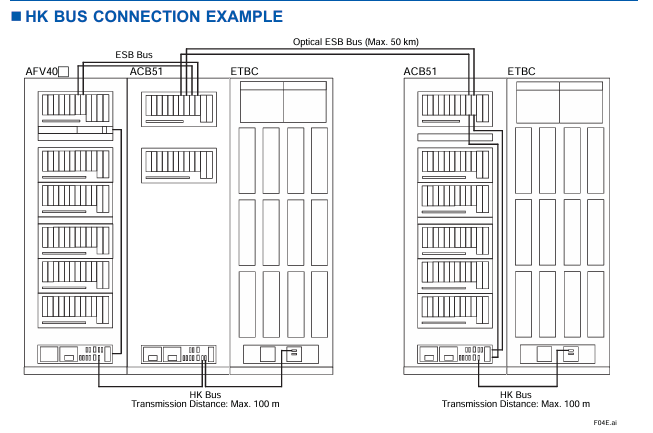
ESB bus interface: AFV40S supports single configuration or dual redundancy, AFV40D enforces dual redundancy and is used to connect FIO node units (ANB10 series) or optical ESB bus relay modules (ANT401/ANT411), expanding on-site I/O access capabilities.
Environmental monitoring (HK function)
Built in HKU (House Keeping Unit) monitors the environmental status of the connected cabinet (such as temperature and fan operation status) through the HK bus or optical ESB bus, and displays the HKU operation status on the HIS (Human Machine Interface), supporting system alarm output.
HK bus parameters: Supports connecting HKUs to cabinets such as ACUKT1/ACUKT2/ACB51/XLCabinet, with a maximum of 9 cabinets connected to a single FCU. The total length of the HK bus cable (AKBHKU) is up to 100 meters (daisy chain connection).
(2) Equipment configuration inside the cabinet
Standard equipment
Each FCU cabinet includes: 1 FCU, 1 distribution board with built-in HKU (supporting single/dual power), 2 vertical power bus units (AEPV7D, 1 front and 1 rear), up to 4 node fan units (ANFAN, 2 front and 2 rear, depending on the number of nodes), and 4 cabinet door fan units (AIP601, 2 front and 2 rear cabinet doors).
FCU module configuration
Power module: Supports PW481/PW482/PW484, dual redundant configuration requires 2 modules of the same model to ensure seamless switching in case of power failure.
Processor module: Supports CP471 (CENTUM VP R6.05 and above) or CP461 (default standard), dual redundancy configuration requires 2 modules of the same model, and only authorized engineers from Yokogawa can perform the replacement of CP461 to CP471.
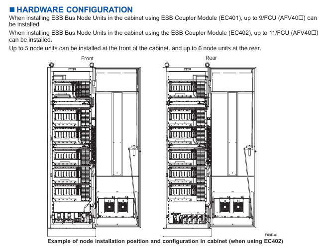
ESB bus coupler module: Supports EC401 (single/dual redundancy) or EC402 (single/dual redundancy), with two identical modules required for dual redundancy configuration to expand ESB bus nodes (EC401 supports up to 9 nodes, EC402 supports up to 11 nodes).
I/O module: Supports up to 6 non-standard I/O modules, which need to be selected according to the type of on-site signal (such as analog input, digital output) and adapted to the FIO system.
(3) Power supply and power consumption
Description of parameters AFV40S/AFV40D (maximum node configuration)
The supply voltage of 100-120V AC/220-240V AC (50/60Hz) and 24V DC should be specified through suffix codes, such as "1" representing 100-120V AC and "4" representing 24V DC
Maximum power consumption (100-120V AC) 2500VA node unit power consumption at full configuration, reduced power consumption in single node configuration
Maximum power consumption (220-240V AC) 2860VA-
Maximum power consumption (24V DC) 71A-
Power protection dual power redundancy (AFV40D mandatory, AFV40S optional) The distribution board supports dual power input and automatically switches in case of failure
(4) Mechanical and environmental parameters
Cabinet size and weight
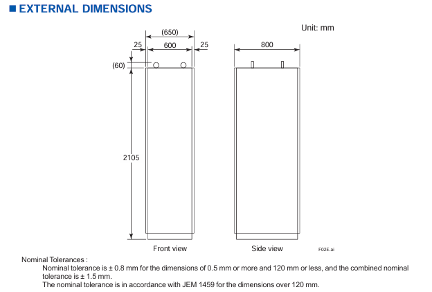
Dimensions (width x depth x height): approximately 600mm x 800mm x 2105mm (including cabinet), with dimensional tolerances in accordance with the JEM 1459 standard (± 0.8mm below 120mm, standard tolerances above 120mm).
Weight: The empty cabinet weighs about 240kg, and the maximum node configuration (11 node units) is about 360kg. During installation, it is necessary to ensure that the load-bearing bracket of the cabinet meets the load requirements.
environmental adaptability
Working temperature: -10 ℃~+50 ℃ (depending on the cabinet door fan and node fan for heat dissipation); Storage temperature: -20 ℃~+60 ℃.
Protection level: IP20 (only applicable to internal components of the cabinet, must be installed in a closed cabinet to avoid direct contact with dust and liquids).
Anti interference: Compliant with industrial electromagnetic compatibility (EMC) standards, refer to the CENTUM VP system overview document (GS33J01A10-01EN) for details.
Installation restrictions and configuration requirements
(1) Node unit expansion restrictions
Number and type of nodes
A single FCU can support up to 13 node units, including ESB bus node units (ANB10 series) and optical ESB bus relay module units (ANT10U), and can install up to 11 units in the cabinet (5 in the front and 6 in the back).
Remote node expansion: It needs to be connected through the optical ESB bus relay main module (ANT401/ANT411), and the relay module needs to be installed in slots 1-6 of the FCU (dual redundant configuration needs to be installed in pairs, single configuration needs to be installed in the order of slots 1, 3, and 5). The maximum transmission distance of the optical fiber cable is 50km.
Fan unit selection rules
The number of node fan units (ANFAN) should be determined based on the total number of node units in the cabinet to ensure sufficient heat dissipation and avoid module overheating
Number of required node fan units for the total number of node units (ANB10+ANT10U) in the cabinet
0-4 1
5-9 2
10 3
11 4
(2) Hardware Installation Specification
Cabinet grounding and wiring
Power wiring: M6 screw terminals are used, supporting dual power systems (main/backup power needs to be distinguished), and the input voltage should be consistent with the suffix code (such as 100-120V AC or 24V DC).
Grounding requirements: Use M8 screw terminals, with a protective grounding (PE) resistance of ≤ 4 Ω, to ensure the safety of personnel and equipment in case of leakage.
READY contact wiring: M4 screw terminals are used, and NC/NO contacts need to be selected according to the requirements of external alarm devices.
Module installation sequence
The node units inside the cabinet need to be installed in the order of "ANB10 series (ESB bus nodes) first, then ANT10U (optical ESB relay units)" to avoid communication conflicts.
The dual redundant modules (power supply, processor, ESB coupler) need to be installed in adjacent slots to ensure synchronization of redundant switching signals.
Cable restrictions
HK bus cable (AKBHKU): total length ≤ 100 meters. When connecting multiple cabinets in a daisy chain, the length of each cable segment needs to be included in the total length.
ESB bus cable (YCB301): The pre wiring inside the cabinet has been completed, but the cable between ANB10 and ANT10U needs to be connected on site, and parallel laying with power cables should be avoided (spacing ≥ 300mm) to reduce electromagnetic interference.
Model code and configuration options
(1) AFV40S (Single Field Control Unit) Model Code
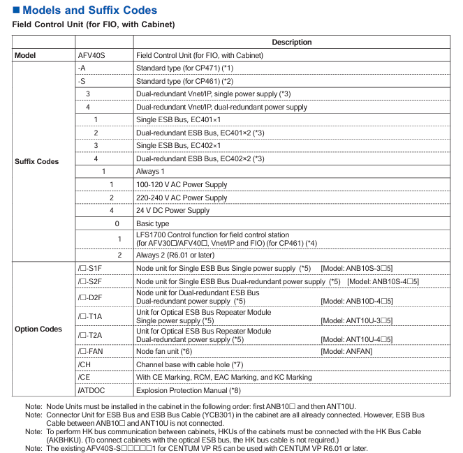
Model format: AFV40S - [suffix code 1] [suffix code 2] [suffix code 3] [suffix code 4] [suffix code 5] [suffix code 6] [suffix code 7]+option code Core suffix code meaning:
Description of optional values for suffix code bits
1 (Type) A/S A=compatible with CP471 processor (R6.05 and above); S=Compatible with CP461 processor (default)
2 (Vnet/IP) 3/4 3=dual redundant Vnet/IP+single power supply; 4=Dual redundant Vnet/IP+dual power supply
3 (ESB bus) 1/2/3/4 1=single ESB (EC401 × 1); 2=Dual redundant ESB (EC401 × 2); 3=Single ESB (EC402 × 1); 4=Dual redundant ESB (EC402 × 2)
5 (power type) 1/2/4 1=100-120V AC; 2=220-240V AC; 4=24V DC
Option code (optional as needed):
/ - S1F: Single ESB bus node unit (single power supply, model ANB10S-3 5), is the number of units (1-9/A=10/B=11).
/ - FAN: Node Fan Unit (ANFAN), is the number of fans (1-4, determined by the total number of nodes).
/CH: Channel base with cable holes (rear 300 × 40mm hole, factory equipped with filling plate), but CE/RCM/EMC/KC certification cannot be selected at the same time after selecting this option.
/ATDOC: Includes explosion-proof manual (compliant with ATEX directive, applicable to potentially explosive environments).
(2) AFV40D (Dual Redundant Field Control Unit) Model Code
Model format: AFV40D - [suffix code 1] [suffix code 2] [suffix code 3] [suffix code 4] [suffix code 5] [suffix code 6] [suffix code 7]+Option code Core difference: AFV40D requires dual redundancy configuration, suffix code 2 is fixed as "4" (dual redundant Vnet/IP+dual power supply), suffix code 3 is fixed as "2/4" (dual redundant ESB bus), and option code only supports dual redundant node units (such as/ - D2F, dual redundant ESB node units).
Software requirements and compatible systems
software license
AFV40S/AFV40D require separate purchase of software license, core dependencies:
VP6F1700 Field Control Station Control Function License (GS33J15C10-01EN): Supports the control logic operation of CP461/CP471 processors.
VP6F3100 Project I/O License (GS33J15A10-01EN): Supports I/O node expansion and signal acquisition for FIO systems.
Event Sequence Manager (SEM) compatibility
If SEM functions (event collection, timestamp recording) are required, hardware conditions must be met (such as supporting high-precision time synchronization), please refer to the document "GS33J30D10-01EN" for details.
system compatibility
Only compatible with Yokogawa CENTUM VP integrated production control system, supporting R6.01 and above versions, with CP471 processor requiring R6.05 and above versions; Seamless integration with FIO system, optical ESB bus relay module (ANT401/ANT411), HKU compatible cabinet (ACUKT1, etc.).
Attachments and related products
Standard Appendix
Factory standard: Cabinet door filter (model T9070CB, quantity 2), used to filter the dust in the cabinet inlet air, needs to be replaced regularly to ensure heat dissipation effect.
Related Products
Cabinet Connection Kit: AKT211, used for HK bus or power connection between multiple AFV40 cabinets.
Cabinet side panel: ACB2P, 2 pieces per cabinet (1 on each side) are required for cabinet side protection and need to be ordered separately.
ESB bus cable: YCB301, pre wired in the cabinet already included, additional configuration is required for the connection between ANB10 and ANT10U.
Key application precautions
Effectiveness of redundant configuration
The dual redundancy function of AFV40D must ensure that the "power supply, processor, and ESB bus module" are all of the same model and installed in designated redundancy slots, otherwise automatic fault switching cannot be achieved.
Explosion proof environment use
If used in potentially explosive environments (such as Zone 2), select the/ATDOC option code, obtain the explosion-proof manual, and ensure that the cabinet and node units comply with ATEX/IECEX certification requirements.
Maintenance and replacement
The replacement of processor modules (CP461 → CP471) is only allowed to be operated by authorized engineers from Yokogawa. User initiated replacement will result in the warranty being invalidated; The battery needs to be replaced every 3-5 years to avoid data loss during power outages.
- YOKOGAWA
- Reliance
- ADVANCED
- SEW
- ProSoft
- WATLOW
- Kongsberg
- FANUC
- VSD
- DCS
- PLC
- man-machine
- Covid-19
- Energy and Gender
- Energy Access
- Renewable Integration
- Energy Subsidies
- Energy and Water
- Net zero emission
- Energy Security
- Critical Minerals
- A-B
- petroleum
- Mine scale
- Sewage treatment
- cement
- architecture
- Industrial information
- New energy
- Automobile market
- electricity
- Construction site
- HIMA
- ABB
- Rockwell
- Schneider Modicon
- Siemens
- xYCOM
- Yaskawa
- Woodward
- BOSCH Rexroth
- MOOG
- General Electric
- American NI
- Rolls-Royce
- CTI
- Honeywell
- EMERSON
- MAN
- GE
- TRICONEX
- Control Wave
- ALSTOM
- AMAT
- STUDER
- KONGSBERG
- MOTOROLA
- DANAHER MOTION
- Bentley
- Galil
- EATON
- MOLEX
- Triconex
- DEIF
- B&W
- ZYGO
- Aerotech
- DANFOSS
- KOLLMORGEN
- Beijer
- Endress+Hauser
- schneider
- Foxboro
- KB
- REXROTH
- YAMAHA
- Johnson
- Westinghouse
- WAGO
- TOSHIBA
- TEKTRONIX
- BENDER
- BMCM
- SMC
- HITACHI
- HIRSCHMANN
- XP POWER
- Baldor
- Meggitt
- SHINKAWA
- Other Brands
- UniOP
- KUKA
- IBA
- Beckhoff
- ADLINK
-
ADLINK HPCI-14S12U - Industrial Control Backplane 12PCI Backplane PCI-14S Passive Backplane
-
ADLINK PCIe-GIE74C - image acquisition card 4-CH GigE Vision PoE+ Frame Grabber
-
ADLINK PCI-8164 - control card 4-Axis Advanced Motion Controller Board
-
ADLINK PCIe-U304 - 4 Port USB3 PCIe Frame Grabbers USB Screw Hole Card
-
ADLINK PCI-9112 - Multi-Function Data Acquisition Card DAQ Card
-
ADLINK PCI-7432 - 51-12013-0A50 4-CH Isolated Numérique I/O PCI Cartes Digital I/O Card
-
ADLINK PCA-6106P3-0C1 REV.C1 - backplane 6-Slot Passive Backplane Board
-
ADLINK PCI-7224 - 24-CH Opto-Isolated Digital I/O PCI Board
-
ADLINK CPCI-7433R(G) - Digital Input Board Rear I/O CompactPCI Card
-
ADLINK EBP-13E4 - 51-46703-0A30 Industrial PC Backplane Passive Backplane
-
ADLINK PCIE-HDV62 - Image acquisition card High Definition Video Frame Grabber
-
ADLINK EBP-13E4 - 51-46703-0A30 Industrial Backplane Board Passive Backplane
-
ADLINK 90111-B1 / CPCI-6770 - PCB CPU MODULE CompactPCI Single Board Computer
-
ADLINK PCI-7248 - DATA ACQUISITION PCI CARD 48-CH Parallel Digital I/O Board
-
ADLINK PCI-7230 - 51-12003-0a50 board PCI7230 32-CH Isolated Digital I/O Card
-
ADLINK PCI2A000CB - 51-20000-0B30 Multi-Function DAQ Card Baseboard
-
ADLINK PCI-8134-005 - 4-Axis Motion Controller Card
-
ADLINK PCI-7224 - 24-CH Opto-Isolated Digital I/O PCI Card
-
ADLINK PCI-7434 - 64-CH Isolated Digital Output Card
-
ADLINK PCI-8132 - motion control card 2-Axis Servo & Stepper Controller
-
ADLINK PCI-8134 - Motion Controller PCI Card 4-Axis Controller Board
-
ADLINK PCI-8164 - Motion Control Card 51-12406-0A40 4-Axis Controller
-
ADLINK 51-12001-0C20 - Circuit Board Data Acquisition Interface Module Hardware
-
ADLINK NuPR0-840 - industrial control motherboard Full-Size PICMG CPU Board
-
ADLINK PCI-7444 - 51-12023-0A10 card 128-CH Isolated Digital Output Board
-
ADLINK PCI-1612B - data acquisition card 4-Port RS-232/422/485 Serial Communication Card
-
ADLINK PCI-6208V 009 - 8/16-CH 16-Bit Analog Output Cards PCB-I-E-482=6BX3
-
ADLINK NUPRO-935A/LV - industrial control motherboard Full-Size PICMG SBC Board
-
ADLINK PCI-9114DG - Multi-Function DAQ Card Data Acquisition PCI Card
-
ADLINK ACL-7130 - Data acquisition card Isolated Digital I/O Board
-
ADLINK ABX-6300D-4E1-BP - board ABX6300D4E1BP Video Interface Expansion Card
-
ADLINK CPCI-6940 - CPCI-6940/D1539/M16-0(EA)-000E 6U CompactPCI Processor Board
-
ADLINK NuPRO-760 - industrial control motherboard Half-Size PICMG SBC CPU Board
-
ADLINK IMB-M42H (G)-0020 - industrial control motherboard LGA1155 Micro-ATX Mainboard
-
ADLINK RTV-24 / PCI-MP4S - 51-12519-1C30 4-Channel Real Time Video Capture Board
-
ADLINK PCI-8134 - 4-Axis Servo & Stepper Motion Controller Card
-
ADLINK MXC-6101D - V.PC000.002.ST.00 Box PC Configurable Embedded Computer
-
ADLINK PCI-8134A - 51-12421-0A10 Motion Control Card 4-Axis Controller Card
-
ADLINK DIN-100S / DIN-100SA1 - Technology SCSI-II TB 100-PIN Terminal Block Board
-
ADLINK DIN-812M001 / DIN812M001 - 51-14034-0A1 51140340A1 Terminal Module Breakout Interface
-
ADLINK PCI-8164 - Servo motion control 4-Axis Advanced Controller Card
-
ADLINK PCIe-GIE64 - Acquisition card GigE Vision PoE+ Frame Grabber
-
ADLINK M-302 - Industrial control motherboard ATX PC Board Mainboard
-
ADLINK PCI-8134 - Motion Controller PCI Card 4-Axis Controller Board
-
ADLINK PCI-RTV24 - Image capture card Analog Video Frame Grabber
-
ADLINK PCI-8102 - Motion control card 2-Axis Servo & Stepper Controller Board
-
ADLINK PCI-9112 REV.B1 - Card Multi-Function Data Acquisition Card
-
ADLINK HSI-DI32-M-N / HSL-TB32-M-DIN - Discrete I/O MODULE Distributed Automation Module System
-
ADLINK PCI-7296 - IO card REV.A3 96-CH Parallel Digital I/O Card
-
ADLINK DIN-814P-A4 / 814Y - terminal board Motion Control Interface Block
-
ADLINK DIN-814P-A4 - 51-14056-0A10 PCB-I-E-2736=ZA01 Screw Terminal Board Breakout
-
ADLINK M-322 - motherboard Industrial Control Computer Mainboard
-
ADLINK NUPRO-406 REV:B1 - industrial control motherboard Full-Size PICMG CPU Board
-
ADLINK AMP-204C - card DSP-Based 4-Axis Advanced Pulse-Train Controller
-
ADLINK HPCI14S REV.B1 - industrial computer baseboard 14-Slot Passive Backplane
-
ADLINK PCI-7250 - 8-CH Relay Output & 8-CH Isolated DI PCI Card
-
ADLINK EBP-13E2 - baseplate Passive Backplane Industrial Computer Chassis Board
-
ADLINK LPCI-3488A - PCI-GPIB card 51-12801-0A30 acquisition card IEEE-488 Interface Board
-
ADLINK PCI-6216V-GL - 51-12201-0C30 16-CH 16-Bit Voltage Analog Output Card
-
ADLINK ACL-8454 - 16-CH Isolated Digital I/O & 4-CH Counter Card
-
ADLINK HPCI-9S7U - backplane Passive Backplane Compatible with NuPRO-A301 852 841 842
-
ADLINK DAQ-2010-007 - Simultaneous-Sampling Multi-Function Data Acquisition Card
-
ADLINK MP-C154 - 51-64205-0A10 Motion Control Card 4-Axis Controller Board
-
ADLINK MXE-202/mSSD16B/WiFi-BT - Matrix Rugged I/O Platform Embedded Fanless Computer
-
ADLINK CM-920-R-17 - PC/104-Plus Single Board Computer Module Intel Celeron M
-
ADLINK PCI-7250 NSMP - 8-CH Relay Output & 8-CH Isolated DI Card
-
ADLINK PCI-8164 - 4-Axis Motion Controller PCI Card W/ Cable and Breakout Box
-
ADLINK EMX-100 - Ethernet-based 4-axis Motion Controllers Distributed Motion Module
-
ADLINK PCI-8134A - Press control card 4-Axis Motion Controller Board
-
ADLINK M-845EG REV:3.2 - industrial motherboard Pentium 4 Socket 478 Micro-ATX
-
ADLINK PCI-9114A Rev A2 DG - card High-Resolution Multi-Function Data Acquisition Board
-
ADLINK IEC-915GV - REV 1.1 Industrial motherboard Socket 478 CPU Board
-
ADLINK PCI-9111DG(G) - Data Acquisition Card Multi-Function DAQ Card
-
ADLINK HPCI-15S10 REV:B2 - Industrial computer base plate Passive Backplane Board
-
ADLINK NuPR0-840 / NuPR0-840DV - industrial control motherboard Full-size PICMG CPU Board
-
ADLINK RTV-24 / PCI-MP4S - 51-12519-1C30 4-Channel Real Time Video Capture Board
-
ADLINK NUPRO-780 - industrial control motherboard Pentium III Single Board Computer
-
ADLINK PCI-7296 - 0050 card 96-CH Opto-Isolated Parallel DIO Card Set
-
ADLINK NUPRO-780 - industrial control motherboard PICMG Full-Size SBC
-
ADLINK PCI-7248 - 51-12006-0A3 002 Pci 7248 48-CH Parallel Digital I/O Card
-
ADLINK PCI-7230 - 32-CH Isolated Digital I/O Card
-
ADLINK AMP-204C - motion control card 4-Axis Advanced Controller Board
-
ADLINK PCI-1714UL - Card Ultra High-Speed 4-CH Simultaneous Sampling DAQ
-
ADLINK NuPRO-E330 - industrial computer equipment motherboard PICMG 1.3 SHB SBC
-
ADLINK AMP-204C - DSP-Based 4-Axis Advanced Pulse-Train Motion Controller Module
-
ADLINK PCI-7256 - 001 51-12206-0A2 REV.A2 LPCI-7256 16-CH Latching Relay Output Card
-
ADLINK ND6050 - NUDAM DIGITAL I/0 MODULE Distributed I/O Unit
-
ASEM BM100 - Box PC Embedded Fanless Industrial Computer
-
ADLINK PCI-7250 - PCI Acquisition Card 8-CH Relay Output & Isolated DI Board
-
ADLINK PCI-8164 - Servo motion control 4-Axis Controller Card
-
ADLINK NuPRO-A40H - Industrial Motherboard 51-41807-1A30 OSP LGA1155 H61
-
ADLINK ADMAX X300 SERVER - 51066010-0A30 motherboard Multi-Processor Mainboard
-
ADLINK CMe-GIE62+ - 51-32903-0A30 control card PC/104-Plus GigE Vision Frame Grabber
-
ADLINK NUPRO-780 - industrial control motherboard Full-Size PICMG SBC CPU Board
-
ADLINK ETX-AT-N270-18/GKTEL - 51-71111-OB10 motherboard ETX CPU Module Board
-
ADLINK DIN-812M - interface module Terminal Block Connection Board
-
ADLINK IMB-M42H - industrial control motherboard LGA1155 Micro-ATX Mainboard
-
ADLINK PXIS-2508 - 8-slot 3U PXI Instrument Chassis Power Hardware Assembly
-
ADLINK AMP-208C - Motion Control card DSP-Based 8-Axis Pulse-Train Controller
-
ADLINK PCI-9111 / PCI-9111DG - Multi-Function Data Acquisition Card DAQ Board
-
ADLINK IEEE-488 GPIB card - Bus Interface Controller Communication Board
-
ADLINK RTV-24 - 51-12519-1C30 image acquisition card Video Frame Grabber Card
-
ADLINK TB-24P/24-01 - Board 24 Way Screw Terminal Breakout Board
-
ADLINK HSL-DI16DO16-DB-NN - 51-23015-0A40 Distributed Discrete I/O Module Set
-
ADLINK PCI-7442 - switch quantity card data acquisition card 64-CH Isolated Card
-
ADLINK ACL-7130 REV. B2 - industrial control capture card Isolated Digital I/O PCI Card
-
ADLINK PCI-6S / PCI6S - Backplane 6-Slot Passive Backplane Chassis Board
-
ADLINK ACL-8113A - card Isolated Digital Input Card
-
ADLINK CPCI-6208V-003 - board cPCI CompactPCI 8-CH Analog Output Card
-
ADLINK DIN-100S-01(G) - SCSI 100-Pin Terminal Block Interface Board
-
ADLINK PCI-7433 - Isolated Digital Input Card 64-CH
-
ADLINK PCI-9812 - Synchronous sampling analog input card High-Speed DAQ Board
-
ADLINK PCI-7434 REV.B1 - PLOTECH PCB-I-E-1182=6EX2 64-CH Isolated Digital Output Card
-
ADLINK PCIe-RTV24 - 51-18016-0A20 4-CH Real-Time Video Capture Card PCIe Frame Grabber
-
ADLINK PCI-8144 / PCI-8144N - Motion control card 4-Axis Stepper Motor Controller
-
ADLINK DIN-68S-01 - terminal board 68-Pin Connector Terminal Block
-
ADLINK MP-C154 - Motion control card 4-Axis Advanced Controller Card
-
ADLINK PCI-7248 (G) - Motherboard 48-CH Parallel Digital I/O Card
-
ADLINK MXE-1301(G) - Intel Atom D2550+NM10 MXE 1300 Series 93-4130-0030 Embedded Computer
-
ADLINK PRO-841 Rev 2.0 / PRO-060907000670 - CPU 2.26GHz & RAM Industrial PC Board
-
ADLINK NuPRO-E330 - Industrial Motherboard System Host Board PICMG 1.3 SHB
-
ADLINK EBP-13E2 - Passive Backplane Industrial Chassis Baseboard
-
ADLINK PCI-8154 - 4-axis Motion Control Card Servo & Stepper Controller Board
-
ADLINK NuPrO-596 REV.B1 - industrial control motherboard Half-size PICMG CPU Board
-
ADLINK PCI-7852 / PCI-7851 - PLOTECH High-Speed Link Control Card Interface Board
-
ADLINK PCI-9112 - 51-12252-0D20 data acquisition card Multi-Function DAQ
-
ADLINK PCI-9112 - Circuit Board 51-12252-0C20 Multi-Function Data Acquisition Card
-
ADLINK NUPRO-761 REV:1.1 - industrial control motherboard PICMG Full-Size CPU Board

K-JIANG

Add: Jimei North Road, Jimei District, Xiamen, Fujian, China
Tell:+86-15305925923