
K-WANG


KOLLMORGEN AKD ®- N servo drive
Grounding requirements: If the leakage current is greater than 3.5mA, double PE wiring or PE cables with a cross-section greater than 10mm ² should be used, and the installation plate should be made of non painted conductive material to avoid EMC interference.
Electrostatic protection: The equipment contains electrostatic sensitive components inside, and human static electricity must be released before operation to avoid contact with insulating materials (such as synthetic clothing). The equipment should be placed on a conductive surface.
KOLLMORGEN AKD ®- N servo drive
Product Safety and Lifecycle Management
(1) Core safety warnings and compliance requirements
Electrical safety
High voltage risk: The DC bus voltage of the driver can reach up to 900V, and it takes 7 minutes for the residual voltage of the capacitor to drop below 50V after power failure. Before operation, the bus voltage must be measured (AKD-C test X14 terminal, MKD-C test X23 terminal).
Grounding requirements: If the leakage current is greater than 3.5mA, double PE wiring or PE cables with a cross-section greater than 10mm ² should be used, and the installation plate should be made of non painted conductive material to avoid EMC interference.
Electrostatic protection: The equipment contains electrostatic sensitive components inside, and human static electricity must be released before operation to avoid contact with insulating materials (such as synthetic clothing). The equipment should be placed on a conductive surface.
Mechanical safety
High temperature protection: During operation, the temperature of the drive casing may exceed 80 ℃. Before contact, it should be cooled to below 40 ℃ to avoid burns.
Automatic restart risk: When the parameter DRV. ENDEFAULT=1, automatic restart may occur after power on, voltage drop, or power failure recovery. A "Warning: Possible Automatic Startup" sign should be posted in the hazardous area of the machine.
Suspension load protection: An additional mechanical braking device (such as motor brake) should be installed on the vertical axis, and MOTOR.BRAKEIM=1 should be set to ensure that the brake is immediately applied in case of a fault to prevent the load from falling.
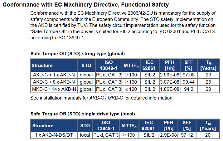
Compliance certification: Compliant with the EC Machinery Directive (2006/42/EU), Low Voltage Directive (2014/35/EU), EMC Directive (2014/30/EU), UL/cUL (document number E217428), EAC, RoHS (2011/65/EU), REACH certification, STO function meets IEC 62061 SIL 2, ISO 13849-1 PLd/CAT 3 safety level.
(2) Product Lifecycle Management
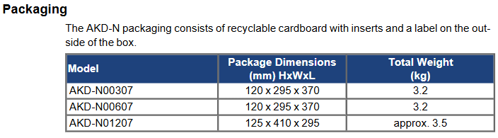
Packaging and Shipping
Packaging specifications: Recyclable cardboard packaging is used, with slight differences in size among different models (such as AKD-N00307 packaging size of 120 × 295 × 370mm, weight of 3.2kg), with a maximum stacking height of 8 boxes.
Transportation conditions: temperature -25~+70 ℃ (temperature change rate ≤ 20K/hour), relative humidity ≤ 95% (no condensation), avoid impact, and require personnel with knowledge of electrostatic protection to operate.
Storage and maintenance
Storage conditions: temperature -25~+55 ℃, relative humidity 5%~95% (no condensation), original packaging needs to be retained, maximum stacking height of 8 boxes, recommended storage period not exceeding 2 years (packaging integrity needs to be checked regularly).
Maintenance requirements: No routine maintenance is required, and the wiring tightness and shell integrity should be checked annually by professional personnel; When cleaning, the power should be turned off first, and the outer shell should be wiped with isopropanol (to avoid liquid infiltration into the interior). After cleaning, it should be left to stand for 30 minutes before being powered on.
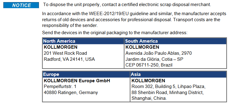
Retirement and disposal: It needs to be dismantled by electrical professionals and recycled through the designated channel of the original factory according to the requirements of the WEEE Directive (2012/19/EU) (such as being sent from China to Room 302, Building 5, Libao Plaza, No. 88 Shenbin Road, Minhang District, Shanghai). Random disposal is prohibited.
Technical parameters and hardware configuration
(1) Core technical parameters
Category parameter item AKD-N00307 AKD-N00607 AKD-N01207
Mechanical parameter weight (kg) 1.6 2.1 2.1
Dimensions (length x width x height, mm) 201 x 130 x 75 201 x 130 x 75 252 x 130 x 75
Electrical parameters Rated supply voltage (VDC) 560~680 560~680 560~680
Continuous output current (Arms, optimal cooling) 3 6 12
Peak output current (Arms, 5s) 9 18 30
Continuous output power (kW, optimal cooling) 1.3 2.6 5.0
Motor inductance range (mH) 6.3~600 3.2~300 2.5~250
Environmental parameter operating temperature (℃) -10~+40 (4%/K for+40~+55) -10~+40 (4%/K for+40~+55) -10~+40 (4%/K for+40~+55)
Protection level IP65/IP67 (UL Type 4x) IP65/IP67 (UL Type 4x) IP65/IP67 (UL Type 4x)
Vibration level IEC 60721-3-3 Class 3M5 IEC 60721-3-3 Class 3M5 IEC 60721-3-3 Class 3M5
(2) Hardware interface and cable requirements
Core interface definition
Hybrid interface (X1/X2): 7-pin M12 connector, X1 is the "hybrid input" (connected to AKD-C/MKD-C or front stage AKD-N), X2 is the "hybrid output" (connected to rear stage AKD-N), including 3 DC power supplies (± DC-ST, PE) and 4 fieldbus signals (positive and negative), with a maximum current of 18A and a voltage of 850V.
Motor interface (X4): 8-pin M23 connector, transmits motor power (U/V/W/PE), brake signal (± BR), and feedback signal (COM ±) when connected with a hybrid cable; When connected with dual cables, only the motor power and brake signal are transmitted, and the feedback signal is transmitted separately by X5. The maximum current is 15A and the voltage is 630V.
Feedback interface (X5): 17 pin M23 connector (only for DF/DS models), supporting SFD, EnDat 2.1/2.2, BiSS, HIPERFACE and other feedback types, transmitting power (+5V/0V), clock (CLK ±), data (DAT ±) and other signals, with a maximum cable length of 5m.
Digital I/O interface (X3): 8-pin M12 connector, including 3 digital inputs (2 high-speed inputs, update rate 2 μ s); 1 standard input, update rate of 250 μ s), 1 digital output (maximum 30VDC/100mA), DS/DT models additionally include 2 STO status outputs.
Optional interface (X6): 4-pin M12 connector, DF/DG model for three-level fieldbus (transceiver ±), DS/DT model for local STO input (± 24V, current 80mA).
Cable requirements: Kollmorgen original cables must be used, with the following key models:
Hybrid cable: CCNCN1-0250 (3 × 2.5mm ²+4 × 0.25mm ², maximum length 40m) is used from AKD-C to AKD-N, and CCNNN1-0250 (maximum length 25m) is used for AKD-N cascading.
Motor cable: CCJNAz-0150 (4 × 1.5mm ²+2 × 0.75mm ²+2 × 0.34mm ², maximum length 5m) is used for hybrid connection, and CMxNAz-0150 (power)+CFyNAz-0020 (feedback) is used for dual cable connection.
STO cable: Phoenix SAC 4P-M12MS (4 × 0.34mm ², maximum length 30m) is used for DS/DT models.
Installation and commissioning process
(1) Mechanical installation
Installation preparation: Ensure that the installation surface is made of conductive material (such as aluminum cold plate), and the size of the cold plate needs to meet the requirements (AKD-N00307 needs 350 × 350 × 10mm, AKD-N01207 needs 480 × 400 × 84mm finned heat sink). The surface flatness error should be ≤ 0.1mm, and a thermal conductive film (model 849-373000-04 for 003/006 model, 849-374001-04 for 012 model) needs to be pasted.
Installation steps:
Fix the driver on the cold plate with 4 M5 hex screws (torque 0.7~0.8Nm), ensuring that there is a heat dissipation space of ≥ 50mm around.
If using the optional heat sink (50mm high), four M4 × 16 screws (torque 0.2~0.25Nm) are needed to secure the heat sink to the bottom of the drive.
Check the installation firmness to avoid loose wiring caused by vibration.
(2) Electrical wiring
Wiring sequence: It is recommended to follow the sequence of "X2 (mixed output) → X1 (mixed input) → X4 (motor) → X5 (feedback) → X3 (I/O) → X6 (optional)" to avoid live operation.
Key wiring specifications:
Power and grounding: PE wires need to be double connected or cables with a cross-sectional area greater than 10mm ² should be used. The cold plate should be reliably connected to the system grounding grid (impedance ≤ 0.1 Ω).
Motor wiring: The U/V/W phase sequence should be consistent with the motor nameplate, and the polarity of the brake wire (± BR) should be confirmed (reverse connection can cause brake failure). The shielding layer of the mixed cable should be grounded through a plug.
Feedback wiring: EnDat/BiSS feedback needs to distinguish between clock and data lines to avoid reverse wiring; The DF/DS model with single cable connection needs to plug AKD-N-JUMP-X5 connector (short circuit Pin4/Pin5) into X5 to ensure feedback power supply.
STO wiring: The local STO input needs to be connected to a PELV level 24V power supply (such as a safety controller output), and the cable needs to be wired separately, away from power cables, to avoid interference.
System topology limitations:
AKD-C single string can connect up to 8 AKD-Ns, MKD-C single string can connect up to 14 (hardware revision C), and the total cable length of a single string is ≤ 100m.
Single string total current: AKD-C two string total ≤ 17A, MKD-C single string ≤ 16A; total power: AKD-C two string total ≤ 11kW, MKD-C single string ≤ 10kW, axis coincidence coefficient needs to be calculated to avoid overload.
(3) System debugging
Preliminary preparation:
Install the WorkBench software (downloaded from DVD or official website) and connect the X18 interface between the PC and AKD-C/MKD-C using an Ethernet cable.
Connect the 24V logic power supply of the system (no main power supply required), confirm that the Ethernet indicator light of AKD-C/MKD-C is on, and that the PC can recognize the driver (distinguished by MAC address or name).
Basic configuration (via Setup Wizard):
Select the driver and configure the IP address (default associated with CAN node address, can be manually modified).
Select the motor model (Kollmorgen motor automatically loads parameters, third-party motors require manual input of rated current, inductance, and other parameters).
Configure feedback type (such as EnDat 2.2), set gear ratio (6091h) and feed in constant (6092h).
Perform motor identification and automatic tuning, optimize current loop and speed loop parameters.
Security function testing:
Global STO test: Send an STO signal through the X16 terminal of AKD-C/MKD-C to confirm that the driver torque is cut off and the motor slides freely.
Local STO test (DS/DT models): Disconnect the STO enable signal (0V) of X6 to confirm that the driver cannot be enabled; After restoring 24V, the driver can start normally.
Functional verification:
Enable the driver (hardware enabled+software enabled), send jog commands through WorkBench, and confirm that the motor direction and speed meet expectations.
Test digital I/O: Set DI1 to "controlled stop" and trigger the motor to stop at the set deceleration (CS. DEC); Check if the output status of DO1 is consistent with the preset function.
Monitoring key parameters: Check the DC bus voltage (VBUS. VALUE), motor current (IL. FB), and temperature (DRV. TEMP) to confirm that there are no abnormal warnings or faults.
Detailed explanation of Safety Functions (STO)
(1) STO types and applicable scenarios
Global STO: Control the STO function of the entire string through AKD-C/MKD-C, suitable for multi axis synchronous safety control, supports 1-14 AKD-N (hardware revision C), response time ≤ 10ms (the more nodes, the faster the response), requires the use of original factory mixed cables, and is prohibited from accessing DS/DT models (not subject to global STO control).
Local STO (DS/DT models only): Independently controls a single driver through the X6 interface, suitable for single axis safety requirements (such as door control interlocking), requires external PELV level 24V power supply, response time ≤ 10ms, STO status output through X3 (for information feedback only, not for safety interlocking).
(2) STO security features
STO Structure ISO 13849-1 IEC 62061 MTTFd (year) PFH (1/h) SFF (%)
AKD-C+1 × AKD-N (global) PLd/CAT3 SIL2 ≥ 100 2.99E-08 97.08
MKD-C+14 × AKD-N (global) PLd/CAT3 SIL2 ≥ 100 1.86E-08 94.20
1 × AKD-N-DS/DT (local) PLd/CAT3 SIL2 ≥ 100 2.90E-08 97.12
(3) Usage restrictions
Prohibited for use in elevator drives, ship/marine environments, explosive environments, and corrosive/conductive dust environments.
STO only cuts off the motor torque and does not provide electrical isolation. During maintenance, it is necessary to disconnect the main power supply and wait for the capacitor to discharge.
An additional mechanical brake is required for the vertical axis, and the motor must be reduced to zero speed and the driver disabled before STO activation.
- YOKOGAWA
- Reliance
- ADVANCED
- SEW
- ProSoft
- WATLOW
- Kongsberg
- FANUC
- VSD
- DCS
- PLC
- man-machine
- Covid-19
- Energy and Gender
- Energy Access
- Renewable Integration
- Energy Subsidies
- Energy and Water
- Net zero emission
- Energy Security
- Critical Minerals
- A-B
- petroleum
- Mine scale
- Sewage treatment
- cement
- architecture
- Industrial information
- New energy
- Automobile market
- electricity
- Construction site
- HIMA
- ABB
- Rockwell
- Schneider Modicon
- Siemens
- xYCOM
- Yaskawa
- Woodward
- BOSCH Rexroth
- MOOG
- General Electric
- American NI
- Rolls-Royce
- CTI
- Honeywell
- EMERSON
- MAN
- GE
- TRICONEX
- Control Wave
- ALSTOM
- AMAT
- STUDER
- KONGSBERG
- MOTOROLA
- DANAHER MOTION
- Bentley
- Galil
- EATON
- MOLEX
- Triconex
- DEIF
- B&W
- ZYGO
- Aerotech
- DANFOSS
- KOLLMORGEN
- Beijer
- Endress+Hauser
- schneider
- Foxboro
- KB
- REXROTH
- YAMAHA
- Johnson
- Westinghouse
- WAGO
- TOSHIBA
- TEKTRONIX
- BENDER
- BMCM
- SMC
- HITACHI
- HIRSCHMANN
- XP POWER
- Baldor
- Meggitt
- SHINKAWA
- Other Brands
- UniOP
- KUKA
- IBA
- Beckhoff
- ADLINK
-
ADLINK HPCI-14S12U - Industrial Control Backplane 12PCI Backplane PCI-14S Passive Backplane
-
ADLINK PCIe-GIE74C - image acquisition card 4-CH GigE Vision PoE+ Frame Grabber
-
ADLINK PCI-8164 - control card 4-Axis Advanced Motion Controller Board
-
ADLINK PCIe-U304 - 4 Port USB3 PCIe Frame Grabbers USB Screw Hole Card
-
ADLINK PCI-9112 - Multi-Function Data Acquisition Card DAQ Card
-
ADLINK PCI-7432 - 51-12013-0A50 4-CH Isolated Numérique I/O PCI Cartes Digital I/O Card
-
ADLINK PCA-6106P3-0C1 REV.C1 - backplane 6-Slot Passive Backplane Board
-
ADLINK PCI-7224 - 24-CH Opto-Isolated Digital I/O PCI Board
-
ADLINK CPCI-7433R(G) - Digital Input Board Rear I/O CompactPCI Card
-
ADLINK EBP-13E4 - 51-46703-0A30 Industrial PC Backplane Passive Backplane
-
ADLINK PCIE-HDV62 - Image acquisition card High Definition Video Frame Grabber
-
ADLINK EBP-13E4 - 51-46703-0A30 Industrial Backplane Board Passive Backplane
-
ADLINK 90111-B1 / CPCI-6770 - PCB CPU MODULE CompactPCI Single Board Computer
-
ADLINK PCI-7248 - DATA ACQUISITION PCI CARD 48-CH Parallel Digital I/O Board
-
ADLINK PCI-7230 - 51-12003-0a50 board PCI7230 32-CH Isolated Digital I/O Card
-
ADLINK PCI2A000CB - 51-20000-0B30 Multi-Function DAQ Card Baseboard
-
ADLINK PCI-8134-005 - 4-Axis Motion Controller Card
-
ADLINK PCI-7224 - 24-CH Opto-Isolated Digital I/O PCI Card
-
ADLINK PCI-7434 - 64-CH Isolated Digital Output Card
-
ADLINK PCI-8132 - motion control card 2-Axis Servo & Stepper Controller
-
ADLINK PCI-8134 - Motion Controller PCI Card 4-Axis Controller Board
-
ADLINK PCI-8164 - Motion Control Card 51-12406-0A40 4-Axis Controller
-
ADLINK 51-12001-0C20 - Circuit Board Data Acquisition Interface Module Hardware
-
ADLINK NuPR0-840 - industrial control motherboard Full-Size PICMG CPU Board
-
ADLINK PCI-7444 - 51-12023-0A10 card 128-CH Isolated Digital Output Board
-
ADLINK PCI-1612B - data acquisition card 4-Port RS-232/422/485 Serial Communication Card
-
ADLINK PCI-6208V 009 - 8/16-CH 16-Bit Analog Output Cards PCB-I-E-482=6BX3
-
ADLINK NUPRO-935A/LV - industrial control motherboard Full-Size PICMG SBC Board
-
ADLINK PCI-9114DG - Multi-Function DAQ Card Data Acquisition PCI Card
-
ADLINK ACL-7130 - Data acquisition card Isolated Digital I/O Board
-
ADLINK ABX-6300D-4E1-BP - board ABX6300D4E1BP Video Interface Expansion Card
-
ADLINK CPCI-6940 - CPCI-6940/D1539/M16-0(EA)-000E 6U CompactPCI Processor Board
-
ADLINK NuPRO-760 - industrial control motherboard Half-Size PICMG SBC CPU Board
-
ADLINK IMB-M42H (G)-0020 - industrial control motherboard LGA1155 Micro-ATX Mainboard
-
ADLINK RTV-24 / PCI-MP4S - 51-12519-1C30 4-Channel Real Time Video Capture Board
-
ADLINK PCI-8134 - 4-Axis Servo & Stepper Motion Controller Card
-
ADLINK MXC-6101D - V.PC000.002.ST.00 Box PC Configurable Embedded Computer
-
ADLINK PCI-8134A - 51-12421-0A10 Motion Control Card 4-Axis Controller Card
-
ADLINK DIN-100S / DIN-100SA1 - Technology SCSI-II TB 100-PIN Terminal Block Board
-
ADLINK DIN-812M001 / DIN812M001 - 51-14034-0A1 51140340A1 Terminal Module Breakout Interface
-
ADLINK PCI-8164 - Servo motion control 4-Axis Advanced Controller Card
-
ADLINK PCIe-GIE64 - Acquisition card GigE Vision PoE+ Frame Grabber
-
ADLINK M-302 - Industrial control motherboard ATX PC Board Mainboard
-
ADLINK PCI-8134 - Motion Controller PCI Card 4-Axis Controller Board
-
ADLINK PCI-RTV24 - Image capture card Analog Video Frame Grabber
-
ADLINK PCI-8102 - Motion control card 2-Axis Servo & Stepper Controller Board
-
ADLINK PCI-9112 REV.B1 - Card Multi-Function Data Acquisition Card
-
ADLINK HSI-DI32-M-N / HSL-TB32-M-DIN - Discrete I/O MODULE Distributed Automation Module System
-
ADLINK PCI-7296 - IO card REV.A3 96-CH Parallel Digital I/O Card
-
ADLINK DIN-814P-A4 / 814Y - terminal board Motion Control Interface Block
-
ADLINK DIN-814P-A4 - 51-14056-0A10 PCB-I-E-2736=ZA01 Screw Terminal Board Breakout
-
ADLINK M-322 - motherboard Industrial Control Computer Mainboard
-
ADLINK NUPRO-406 REV:B1 - industrial control motherboard Full-Size PICMG CPU Board
-
ADLINK AMP-204C - card DSP-Based 4-Axis Advanced Pulse-Train Controller
-
ADLINK HPCI14S REV.B1 - industrial computer baseboard 14-Slot Passive Backplane
-
ADLINK PCI-7250 - 8-CH Relay Output & 8-CH Isolated DI PCI Card
-
ADLINK EBP-13E2 - baseplate Passive Backplane Industrial Computer Chassis Board
-
ADLINK LPCI-3488A - PCI-GPIB card 51-12801-0A30 acquisition card IEEE-488 Interface Board
-
ADLINK PCI-6216V-GL - 51-12201-0C30 16-CH 16-Bit Voltage Analog Output Card
-
ADLINK ACL-8454 - 16-CH Isolated Digital I/O & 4-CH Counter Card
-
ADLINK HPCI-9S7U - backplane Passive Backplane Compatible with NuPRO-A301 852 841 842
-
ADLINK DAQ-2010-007 - Simultaneous-Sampling Multi-Function Data Acquisition Card
-
ADLINK MP-C154 - 51-64205-0A10 Motion Control Card 4-Axis Controller Board
-
ADLINK MXE-202/mSSD16B/WiFi-BT - Matrix Rugged I/O Platform Embedded Fanless Computer
-
ADLINK CM-920-R-17 - PC/104-Plus Single Board Computer Module Intel Celeron M
-
ADLINK PCI-7250 NSMP - 8-CH Relay Output & 8-CH Isolated DI Card
-
ADLINK PCI-8164 - 4-Axis Motion Controller PCI Card W/ Cable and Breakout Box
-
ADLINK EMX-100 - Ethernet-based 4-axis Motion Controllers Distributed Motion Module
-
ADLINK PCI-8134A - Press control card 4-Axis Motion Controller Board
-
ADLINK M-845EG REV:3.2 - industrial motherboard Pentium 4 Socket 478 Micro-ATX
-
ADLINK PCI-9114A Rev A2 DG - card High-Resolution Multi-Function Data Acquisition Board
-
ADLINK IEC-915GV - REV 1.1 Industrial motherboard Socket 478 CPU Board
-
ADLINK PCI-9111DG(G) - Data Acquisition Card Multi-Function DAQ Card
-
ADLINK HPCI-15S10 REV:B2 - Industrial computer base plate Passive Backplane Board
-
ADLINK NuPR0-840 / NuPR0-840DV - industrial control motherboard Full-size PICMG CPU Board
-
ADLINK RTV-24 / PCI-MP4S - 51-12519-1C30 4-Channel Real Time Video Capture Board
-
ADLINK NUPRO-780 - industrial control motherboard Pentium III Single Board Computer
-
ADLINK PCI-7296 - 0050 card 96-CH Opto-Isolated Parallel DIO Card Set
-
ADLINK NUPRO-780 - industrial control motherboard PICMG Full-Size SBC
-
ADLINK PCI-7248 - 51-12006-0A3 002 Pci 7248 48-CH Parallel Digital I/O Card
-
ADLINK PCI-7230 - 32-CH Isolated Digital I/O Card
-
ADLINK AMP-204C - motion control card 4-Axis Advanced Controller Board
-
ADLINK PCI-1714UL - Card Ultra High-Speed 4-CH Simultaneous Sampling DAQ
-
ADLINK NuPRO-E330 - industrial computer equipment motherboard PICMG 1.3 SHB SBC
-
ADLINK AMP-204C - DSP-Based 4-Axis Advanced Pulse-Train Motion Controller Module
-
ADLINK PCI-7256 - 001 51-12206-0A2 REV.A2 LPCI-7256 16-CH Latching Relay Output Card
-
ADLINK ND6050 - NUDAM DIGITAL I/0 MODULE Distributed I/O Unit
-
ASEM BM100 - Box PC Embedded Fanless Industrial Computer
-
ADLINK PCI-7250 - PCI Acquisition Card 8-CH Relay Output & Isolated DI Board
-
ADLINK PCI-8164 - Servo motion control 4-Axis Controller Card
-
ADLINK NuPRO-A40H - Industrial Motherboard 51-41807-1A30 OSP LGA1155 H61
-
ADLINK ADMAX X300 SERVER - 51066010-0A30 motherboard Multi-Processor Mainboard
-
ADLINK CMe-GIE62+ - 51-32903-0A30 control card PC/104-Plus GigE Vision Frame Grabber
-
ADLINK NUPRO-780 - industrial control motherboard Full-Size PICMG SBC CPU Board
-
ADLINK ETX-AT-N270-18/GKTEL - 51-71111-OB10 motherboard ETX CPU Module Board
-
ADLINK DIN-812M - interface module Terminal Block Connection Board
-
ADLINK IMB-M42H - industrial control motherboard LGA1155 Micro-ATX Mainboard
-
ADLINK PXIS-2508 - 8-slot 3U PXI Instrument Chassis Power Hardware Assembly
-
ADLINK AMP-208C - Motion Control card DSP-Based 8-Axis Pulse-Train Controller
-
ADLINK PCI-9111 / PCI-9111DG - Multi-Function Data Acquisition Card DAQ Board
-
ADLINK IEEE-488 GPIB card - Bus Interface Controller Communication Board
-
ADLINK RTV-24 - 51-12519-1C30 image acquisition card Video Frame Grabber Card
-
ADLINK TB-24P/24-01 - Board 24 Way Screw Terminal Breakout Board
-
ADLINK HSL-DI16DO16-DB-NN - 51-23015-0A40 Distributed Discrete I/O Module Set
-
ADLINK PCI-7442 - switch quantity card data acquisition card 64-CH Isolated Card
-
ADLINK ACL-7130 REV. B2 - industrial control capture card Isolated Digital I/O PCI Card
-
ADLINK PCI-6S / PCI6S - Backplane 6-Slot Passive Backplane Chassis Board
-
ADLINK ACL-8113A - card Isolated Digital Input Card
-
ADLINK CPCI-6208V-003 - board cPCI CompactPCI 8-CH Analog Output Card
-
ADLINK DIN-100S-01(G) - SCSI 100-Pin Terminal Block Interface Board
-
ADLINK PCI-7433 - Isolated Digital Input Card 64-CH
-
ADLINK PCI-9812 - Synchronous sampling analog input card High-Speed DAQ Board
-
ADLINK PCI-7434 REV.B1 - PLOTECH PCB-I-E-1182=6EX2 64-CH Isolated Digital Output Card
-
ADLINK PCIe-RTV24 - 51-18016-0A20 4-CH Real-Time Video Capture Card PCIe Frame Grabber
-
ADLINK PCI-8144 / PCI-8144N - Motion control card 4-Axis Stepper Motor Controller
-
ADLINK DIN-68S-01 - terminal board 68-Pin Connector Terminal Block
-
ADLINK MP-C154 - Motion control card 4-Axis Advanced Controller Card
-
ADLINK PCI-7248 (G) - Motherboard 48-CH Parallel Digital I/O Card
-
ADLINK MXE-1301(G) - Intel Atom D2550+NM10 MXE 1300 Series 93-4130-0030 Embedded Computer
-
ADLINK PRO-841 Rev 2.0 / PRO-060907000670 - CPU 2.26GHz & RAM Industrial PC Board
-
ADLINK NuPRO-E330 - Industrial Motherboard System Host Board PICMG 1.3 SHB
-
ADLINK EBP-13E2 - Passive Backplane Industrial Chassis Baseboard
-
ADLINK PCI-8154 - 4-axis Motion Control Card Servo & Stepper Controller Board
-
ADLINK NuPrO-596 REV.B1 - industrial control motherboard Half-size PICMG CPU Board
-
ADLINK PCI-7852 / PCI-7851 - PLOTECH High-Speed Link Control Card Interface Board
-
ADLINK PCI-9112 - 51-12252-0D20 data acquisition card Multi-Function DAQ
-
ADLINK PCI-9112 - Circuit Board 51-12252-0C20 Multi-Function Data Acquisition Card
-
ADLINK NUPRO-761 REV:1.1 - industrial control motherboard PICMG Full-Size CPU Board

K-JIANG

Add: Jimei North Road, Jimei District, Xiamen, Fujian, China
Tell:+86-15305925923