
K-WANG


KOLLMORGEN AKM series synchronous servo motor
Supporting resources: Should be used in conjunction with SERVOSTAR servo amplifier installation manual, operating software manual, and accessory manual; The original factory provides pre assembled motor power cables (such as 4 × 1mm ² shielded wire) and rotary transformer cables (4 × 2 × 0.25mm ² twisted pair). When selecting, the cable specifications should be matched according to the motor model.
KOLLMORGEN AKM series synchronous servo motor
Basic Information
Core positioning: The AKM series is a brushless DC synchronous servo motor that uses neodymium iron boron permanent magnet rotors and three-phase stator windings. It is equipped with a hollow shaft rotary transformer feedback as standard, and can be configured with a brake, EnDat encoder, shaft sealing ring, etc. It needs to be combined with a SERVOSTAR servo amplifier to form a closed-loop control system, and direct connection to the mains power is prohibited for operation.
Supporting resources: Should be used in conjunction with SERVOSTAR servo amplifier installation manual, operating software manual, and accessory manual; The original factory provides pre assembled motor power cables (such as 4 × 1mm ² shielded wire) and rotary transformer cables (4 × 2 × 0.25mm ² twisted pair). When selecting, the cable specifications should be matched according to the motor model.
Core technical characteristics and classification of motors
(1) General Technical Parameters
Category parameter item specification
Environmental adaptability to climate category EN 50178 3K3
Operating temperature -5~+40 ℃ (altitude ≤ 1000m), a 6% derating is required for every altitude exceeding 1000m (or a 10K temperature drop offsets the derating)
Protection level: IP65 for the casing, default IP40 for the shaft sleeve (IP65 with shaft sealing ring)
Humidity 95% relative humidity (no condensation)
Electrical characteristics - Insulation class DIN 57530 F
Vibration level DIN ISO 2373 N level
Thermal protection built-in PTC thermistor (155 ℃± 5% action, room temperature resistance ≤ 550 Ω, after action ≥ 1330 Ω)
Mechanical characteristics: Bearing life ≥ 20000 hours (rated condition)
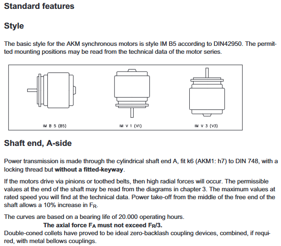
Installation form standard IM B5 (flange installation), supporting orientations such as V1/V3
Shaft end specification: cylindrical shaft (AKM1 with h7 tolerance, others with k6 tolerance), with locking thread, optional keyway (DIN 748)
(2) Optional configuration
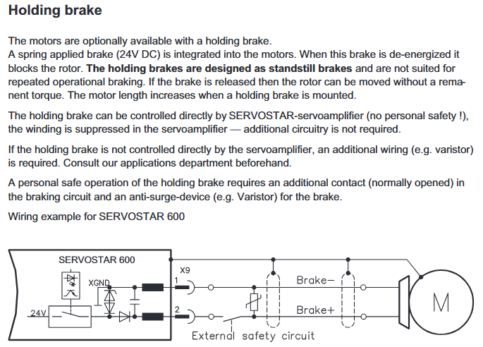
Brake: 24V DC spring compression, braking when power is off, only used for parking braking (frequent operation braking is prohibited). The holding torque of the brake varies for different models (such as AKM2 at 1.42Nm and AKM7 at 53Nm), with a release delay of 20-110ms. When applied, external current components (such as varistors) are required.
Feedback device: Standard 2-pole hollow shaft rotary transformer, optional single/multi turn EnDat encoder (AKM2-4 uses ECN1113/EQN1125, AKM5-7 uses ECN1313/EQN1325) or incremental encoder with commutation signal (Comencoder), the encoder will increase the motor length and cannot be retrofitted.
Shaft sealing ring: anti oil mist/splash, raising the protection level of the shaft sleeve to IP65, not suitable for dry operation scenarios, additional order required.
Keyway: Process the shaft end keyway according to DIN 748, with short keys, and the shaft balance should include the weight of the keys. When selecting, pay attention to the radial force variation (the radial force limit remains unchanged with keyway).
Installation and wiring specifications
(1) Mechanical installation requirements
Installation preparation
Installation surface: It should be made of conductive material (such as aluminum alloy), with a flatness error of ≤ 0.1mm. AKM1/2 should reserve ≥ 50mm of heat dissipation space. AKM3 and above should be matched with designated cold plates (such as AKM3 requiring 350 × 350 × 10mm aluminum plates), and pasted with original thermal conductive film (model 849-373000-04 for small models).
Load limitation: The radial force (FR) allowed at the shaft end is negatively correlated with the rotational speed, for example, at 5000 min ⁻¹, FR=145N for AKM2, and the axial force (FA) ≤ FR/3; The formula for the minimum pulley diameter must be met during belt transmission
D min ≥ M 0/(F R × 2) (M 0 is the static torque) to avoid bearing overload.
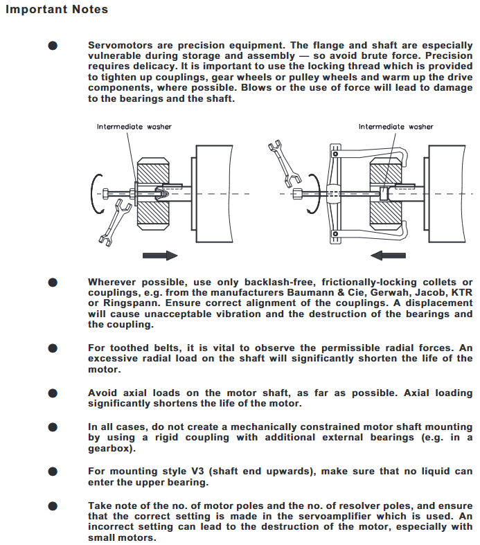
Coupling selection: It is recommended to use friction couplings without backlash (such as Baumann&Cie, KTR brand), with a coaxiality error of ≤ 0.1mm. It is prohibited to use rigid couplings with external bearings for constrained installation to prevent excessive stress on the shaft system.
Installation steps
Clean the installation surface, stick the thermal conductive film (if necessary), and use M5 hex screws (torque 0.7~0.8Nm) to fix the motor, ensuring that the flange fits snugly without any gaps.
Install the coupler/pulley and tighten it with the shaft end locking thread. Do not strike the shaft end (to avoid bearing damage). The AKM1 shaft tolerance is h7, and attention should be paid to the fit clearance.
Check the flexibility of the shaft rotation (without jamming or abnormal noise), and ensure that no liquid enters the upper bearing when installing V3 (with the shaft end facing upwards).
(2) Electrical wiring specifications
Wiring sequence and safety
Power off operation, ensure that the servo amplifier capacitor discharges (after power off for ≥ 5 minutes, measure the DC bus voltage<40V), and the motor junction box needs to be reliably grounded (PE wire cross-section>10mm ² or double PE wiring).
The distance between the power cable and the control cable is ≥ 20cm. If the power cable contains a brake control line (such as 4 × 1+2 × 0.75mm ²), it needs to be shielded separately and grounded at both ends.
When the cable length exceeds 25m, Kollmorgen 3YL-20 choke coil is required (such as SERVOSTAR 601-606 with 4 × 1mm ² cable, 620 with 4 × 2.5mm ² cable).
Core interface definition
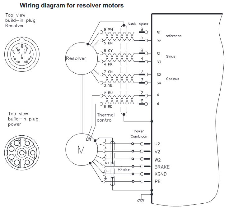
Power interface: 4+4-pole circular connector (AKM1/2 for straight head, AKM3+for elbow), U/V/W connected to motor three-phase winding, PE connected to motor casing, brake wire (± BR) connected to 24V DC (only for brake models).
Feedback interface: The rotary transformer uses a 12 pole circular connector, with R1/R2 as the reference signal, S1/S2 as the sine signal, S3/S4 as the cosine signal, and COM ± as the power supply; The EnDat encoder uses a 17 pole connector, which includes clock (CLK ±), data (DAT ±), and power supply (+5V/0V).
Typical Connection Diagram
Rotary transformer motor: The power end U/V/W/PE is connected to the amplifier output, the feedback end R1/R2/S1/S2/S3/S4 is connected to the amplifier rotary transformer interface, and the PTC thermistor is connected in series to the amplifier overheat protection circuit.
Encoder motor: The encoder clock/data line is connected to the amplifier interface and needs to be separately shielded (with both ends of the shielding layer grounded) to avoid parallel wiring with the power cable.
System debugging and maintenance
(1) Debugging process
Pre inspection
Confirm that the motor is matched with the amplifier (rated voltage and current are consistent), the wiring conforms to the diagrams, and the brake can be released normally after being powered on (no jamming at 24V).
Manually rotate the motor shaft, confirm that there is no mechanical blockage, monitor the bearings for any abnormal noise, and check that the heat dissipation channel is unobstructed (ambient temperature ≤ 40 ℃).
Amplifier configuration
Load motor parameters through SERVOSTAR software (Kollmorgen motor automatically recognizes, third-party motors require manual input of rated torque, inductance, etc.), set the resolution and pole number of the rotary/encoder (to match the actual motor, incorrect settings may burn out the motor).
Perform motor recognition and automatic tuning, optimize current loop and speed loop gains, and conduct multi axis linkage testing after single axis debugging is completed.
Functional Verification
Jogging test: Run at low speed (<100min ⁻¹), confirm that the steering and torque output are normal, monitor the motor temperature (≤ 100 ℃ during operation, cool to 40 ℃ after shutdown and touch again).
Brake test: When the power is cut off, the brake should be immediately applied, and the release should be delayed by ≤ 100ms after power on. The vertical axis should be tested for no load drop after power off (with dual protection of mechanical braking).
(2) Maintenance and Lifecycle Management
routine maintenance
Check the bearing noise every 2500 operating hours or annually. If any abnormal noise occurs, stop the machine and replace the bearing (the bearing grease has a lifespan of 20000 hours and needs to be replaced if it exceeds the deadline).
Wipe the outer shell with isopropanol during cleaning (do not soak or spray), and avoid using solvents such as trichloroethylene and nitro diluents (which may damage the RAL 9005 matte black paint coating).
Storage and transportation
Storage conditions: Temperature -25~+55 ℃, humidity 5%~95% (no condensation), original packaging stacking height not exceeding the limit (such as AKM1/2 stacking 10 boxes, AKM6/7 stacking 1 box), storage period unlimited.
Transportation requirements: Climate category 2K3, temperature -25~+70 ℃ (temperature change rate ≤ 20K/hour), avoid impact, and inspect the appearance of the motor for packaging damage (such as no deformation of the shaft end and flange).
Retirement disposal
According to the requirements of the WEEE directive, qualified electronic waste processors can be used for recycling. They can contact service centers in Kollmorgen to obtain recycling channels (such as sending from Europe to Ratingen factory in Germany and from China to Minhang district office in Shanghai).
Troubleshooting
Common fault handling
Possible causes and solutions for the fault phenomenon
The motor does not rotate. The amplifier is not enabled; 2. The set value signal line is broken; 3. The brake is not released; 4. Motor phase sequence error 1. Sending ENABLE signal; 2. Check the continuity of the set value cable; 3. Confirm that the brake is powered by 24V; 4. Swap the U/V phase sequence
Motor runaway motor phase sequence error or amplifier parameter (such as pole pairs) setting error 1. Emergency stop; 2. Correct the phase sequence or amplifier parameters; 3. Re execute motor identification
Amplifier reports' output stage fault '1. Motor cable short circuit/grounding; 2. Motor winding short circuit: 1. Measure the insulation resistance of the cable (≥ 1M Ω); 2. Disassemble the motor and inspect the winding (replace if burned out)
The amplifier reports "motor overheating". 1. The PTC thermistor is disconnected; 2. Load overload; 3. Poor heat dissipation: 1. Check the PTC wiring; 2. Reduce the load or increase the motor model; 3. Clean the cooling channels and add cooling fans
Brake not braking 1. Brake coil burned out; 2. Axial force overload at the end of the shaft; 3. Insufficient brake torque. 1. Measure the resistance of the brake coil (normally around 6-8 Ω); 2. Check if the axial force is ≤ FR/3 and replace the damaged bearing; 3. Confirm that the brake model matches the motor
Key safety warning
Electrical safety: There may be a high voltage of 900V at the power end of the motor. After power failure, the residual voltage of the capacitor needs to be reduced to the safe value (<40V) within 5 minutes. Before operation, the DC bus voltage must be measured; PE wiring cannot be omitted (leakage current>3.5mA, double PE or large section PE wire to prevent electric shock).
Mechanical safety: The surface temperature of the motor during operation may exceed 100 ℃, and direct touch is prohibited; The keyway at the shaft end needs to be installed with a key before operation to avoid injury caused by centrifugal force throwing out the key; The vertical axis must be equipped with mechanical braking (the holding brake is only used as an auxiliary and requires dual protection in case of malfunction).
Environmental safety: Prohibited from use in explosive or corrosive gas/liquid environments; The motor should be stopped immediately after water ingress, and the insulation resistance (≥ 1M Ω) should be measured after drying before restarting, otherwise it may be short circuited and burned out.
- YOKOGAWA
- Reliance
- ADVANCED
- SEW
- ProSoft
- WATLOW
- Kongsberg
- FANUC
- VSD
- DCS
- PLC
- man-machine
- Covid-19
- Energy and Gender
- Energy Access
- Renewable Integration
- Energy Subsidies
- Energy and Water
- Net zero emission
- Energy Security
- Critical Minerals
- A-B
- petroleum
- Mine scale
- Sewage treatment
- cement
- architecture
- Industrial information
- New energy
- Automobile market
- electricity
- Construction site
- HIMA
- ABB
- Rockwell
- Schneider Modicon
- Siemens
- xYCOM
- Yaskawa
- Woodward
- BOSCH Rexroth
- MOOG
- General Electric
- American NI
- Rolls-Royce
- CTI
- Honeywell
- EMERSON
- MAN
- GE
- TRICONEX
- Control Wave
- ALSTOM
- AMAT
- STUDER
- KONGSBERG
- MOTOROLA
- DANAHER MOTION
- Bentley
- Galil
- EATON
- MOLEX
- Triconex
- DEIF
- B&W
- ZYGO
- Aerotech
- DANFOSS
- KOLLMORGEN
- Beijer
- Endress+Hauser
- schneider
- Foxboro
- KB
- REXROTH
- YAMAHA
- Johnson
- Westinghouse
- WAGO
- TOSHIBA
- TEKTRONIX
- BENDER
- BMCM
- SMC
- HITACHI
- HIRSCHMANN
- XP POWER
- Baldor
- Meggitt
- SHINKAWA
- Other Brands
- UniOP
- KUKA
- IBA
- Beckhoff
- ADLINK
-
ADLINK HPCI-14S12U - Industrial Control Backplane 12PCI Backplane PCI-14S Passive Backplane
-
ADLINK PCIe-GIE74C - image acquisition card 4-CH GigE Vision PoE+ Frame Grabber
-
ADLINK PCI-8164 - control card 4-Axis Advanced Motion Controller Board
-
ADLINK PCIe-U304 - 4 Port USB3 PCIe Frame Grabbers USB Screw Hole Card
-
ADLINK PCI-9112 - Multi-Function Data Acquisition Card DAQ Card
-
ADLINK PCI-7432 - 51-12013-0A50 4-CH Isolated Numérique I/O PCI Cartes Digital I/O Card
-
ADLINK PCA-6106P3-0C1 REV.C1 - backplane 6-Slot Passive Backplane Board
-
ADLINK PCI-7224 - 24-CH Opto-Isolated Digital I/O PCI Board
-
ADLINK CPCI-7433R(G) - Digital Input Board Rear I/O CompactPCI Card
-
ADLINK EBP-13E4 - 51-46703-0A30 Industrial PC Backplane Passive Backplane
-
ADLINK PCIE-HDV62 - Image acquisition card High Definition Video Frame Grabber
-
ADLINK EBP-13E4 - 51-46703-0A30 Industrial Backplane Board Passive Backplane
-
ADLINK 90111-B1 / CPCI-6770 - PCB CPU MODULE CompactPCI Single Board Computer
-
ADLINK PCI-7248 - DATA ACQUISITION PCI CARD 48-CH Parallel Digital I/O Board
-
ADLINK PCI-7230 - 51-12003-0a50 board PCI7230 32-CH Isolated Digital I/O Card
-
ADLINK PCI2A000CB - 51-20000-0B30 Multi-Function DAQ Card Baseboard
-
ADLINK PCI-8134-005 - 4-Axis Motion Controller Card
-
ADLINK PCI-7224 - 24-CH Opto-Isolated Digital I/O PCI Card
-
ADLINK PCI-7434 - 64-CH Isolated Digital Output Card
-
ADLINK PCI-8132 - motion control card 2-Axis Servo & Stepper Controller
-
ADLINK PCI-8134 - Motion Controller PCI Card 4-Axis Controller Board
-
ADLINK PCI-8164 - Motion Control Card 51-12406-0A40 4-Axis Controller
-
ADLINK 51-12001-0C20 - Circuit Board Data Acquisition Interface Module Hardware
-
ADLINK NuPR0-840 - industrial control motherboard Full-Size PICMG CPU Board
-
ADLINK PCI-7444 - 51-12023-0A10 card 128-CH Isolated Digital Output Board
-
ADLINK PCI-1612B - data acquisition card 4-Port RS-232/422/485 Serial Communication Card
-
ADLINK PCI-6208V 009 - 8/16-CH 16-Bit Analog Output Cards PCB-I-E-482=6BX3
-
ADLINK NUPRO-935A/LV - industrial control motherboard Full-Size PICMG SBC Board
-
ADLINK PCI-9114DG - Multi-Function DAQ Card Data Acquisition PCI Card
-
ADLINK ACL-7130 - Data acquisition card Isolated Digital I/O Board
-
ADLINK ABX-6300D-4E1-BP - board ABX6300D4E1BP Video Interface Expansion Card
-
ADLINK CPCI-6940 - CPCI-6940/D1539/M16-0(EA)-000E 6U CompactPCI Processor Board
-
ADLINK NuPRO-760 - industrial control motherboard Half-Size PICMG SBC CPU Board
-
ADLINK IMB-M42H (G)-0020 - industrial control motherboard LGA1155 Micro-ATX Mainboard
-
ADLINK RTV-24 / PCI-MP4S - 51-12519-1C30 4-Channel Real Time Video Capture Board
-
ADLINK PCI-8134 - 4-Axis Servo & Stepper Motion Controller Card
-
ADLINK MXC-6101D - V.PC000.002.ST.00 Box PC Configurable Embedded Computer
-
ADLINK PCI-8134A - 51-12421-0A10 Motion Control Card 4-Axis Controller Card
-
ADLINK DIN-100S / DIN-100SA1 - Technology SCSI-II TB 100-PIN Terminal Block Board
-
ADLINK DIN-812M001 / DIN812M001 - 51-14034-0A1 51140340A1 Terminal Module Breakout Interface
-
ADLINK PCI-8164 - Servo motion control 4-Axis Advanced Controller Card
-
ADLINK PCIe-GIE64 - Acquisition card GigE Vision PoE+ Frame Grabber
-
ADLINK M-302 - Industrial control motherboard ATX PC Board Mainboard
-
ADLINK PCI-8134 - Motion Controller PCI Card 4-Axis Controller Board
-
ADLINK PCI-RTV24 - Image capture card Analog Video Frame Grabber
-
ADLINK PCI-8102 - Motion control card 2-Axis Servo & Stepper Controller Board
-
ADLINK PCI-9112 REV.B1 - Card Multi-Function Data Acquisition Card
-
ADLINK HSI-DI32-M-N / HSL-TB32-M-DIN - Discrete I/O MODULE Distributed Automation Module System
-
ADLINK PCI-7296 - IO card REV.A3 96-CH Parallel Digital I/O Card
-
ADLINK DIN-814P-A4 / 814Y - terminal board Motion Control Interface Block
-
ADLINK DIN-814P-A4 - 51-14056-0A10 PCB-I-E-2736=ZA01 Screw Terminal Board Breakout
-
ADLINK M-322 - motherboard Industrial Control Computer Mainboard
-
ADLINK NUPRO-406 REV:B1 - industrial control motherboard Full-Size PICMG CPU Board
-
ADLINK AMP-204C - card DSP-Based 4-Axis Advanced Pulse-Train Controller
-
ADLINK HPCI14S REV.B1 - industrial computer baseboard 14-Slot Passive Backplane
-
ADLINK PCI-7250 - 8-CH Relay Output & 8-CH Isolated DI PCI Card
-
ADLINK EBP-13E2 - baseplate Passive Backplane Industrial Computer Chassis Board
-
ADLINK LPCI-3488A - PCI-GPIB card 51-12801-0A30 acquisition card IEEE-488 Interface Board
-
ADLINK PCI-6216V-GL - 51-12201-0C30 16-CH 16-Bit Voltage Analog Output Card
-
ADLINK ACL-8454 - 16-CH Isolated Digital I/O & 4-CH Counter Card
-
ADLINK HPCI-9S7U - backplane Passive Backplane Compatible with NuPRO-A301 852 841 842
-
ADLINK DAQ-2010-007 - Simultaneous-Sampling Multi-Function Data Acquisition Card
-
ADLINK MP-C154 - 51-64205-0A10 Motion Control Card 4-Axis Controller Board
-
ADLINK MXE-202/mSSD16B/WiFi-BT - Matrix Rugged I/O Platform Embedded Fanless Computer
-
ADLINK CM-920-R-17 - PC/104-Plus Single Board Computer Module Intel Celeron M
-
ADLINK PCI-7250 NSMP - 8-CH Relay Output & 8-CH Isolated DI Card
-
ADLINK PCI-8164 - 4-Axis Motion Controller PCI Card W/ Cable and Breakout Box
-
ADLINK EMX-100 - Ethernet-based 4-axis Motion Controllers Distributed Motion Module
-
ADLINK PCI-8134A - Press control card 4-Axis Motion Controller Board
-
ADLINK M-845EG REV:3.2 - industrial motherboard Pentium 4 Socket 478 Micro-ATX
-
ADLINK PCI-9114A Rev A2 DG - card High-Resolution Multi-Function Data Acquisition Board
-
ADLINK IEC-915GV - REV 1.1 Industrial motherboard Socket 478 CPU Board
-
ADLINK PCI-9111DG(G) - Data Acquisition Card Multi-Function DAQ Card
-
ADLINK HPCI-15S10 REV:B2 - Industrial computer base plate Passive Backplane Board
-
ADLINK NuPR0-840 / NuPR0-840DV - industrial control motherboard Full-size PICMG CPU Board
-
ADLINK RTV-24 / PCI-MP4S - 51-12519-1C30 4-Channel Real Time Video Capture Board
-
ADLINK NUPRO-780 - industrial control motherboard Pentium III Single Board Computer
-
ADLINK PCI-7296 - 0050 card 96-CH Opto-Isolated Parallel DIO Card Set
-
ADLINK NUPRO-780 - industrial control motherboard PICMG Full-Size SBC
-
ADLINK PCI-7248 - 51-12006-0A3 002 Pci 7248 48-CH Parallel Digital I/O Card
-
ADLINK PCI-7230 - 32-CH Isolated Digital I/O Card
-
ADLINK AMP-204C - motion control card 4-Axis Advanced Controller Board
-
ADLINK PCI-1714UL - Card Ultra High-Speed 4-CH Simultaneous Sampling DAQ
-
ADLINK NuPRO-E330 - industrial computer equipment motherboard PICMG 1.3 SHB SBC
-
ADLINK AMP-204C - DSP-Based 4-Axis Advanced Pulse-Train Motion Controller Module
-
ADLINK PCI-7256 - 001 51-12206-0A2 REV.A2 LPCI-7256 16-CH Latching Relay Output Card
-
ADLINK ND6050 - NUDAM DIGITAL I/0 MODULE Distributed I/O Unit
-
ASEM BM100 - Box PC Embedded Fanless Industrial Computer
-
ADLINK PCI-7250 - PCI Acquisition Card 8-CH Relay Output & Isolated DI Board
-
ADLINK PCI-8164 - Servo motion control 4-Axis Controller Card
-
ADLINK NuPRO-A40H - Industrial Motherboard 51-41807-1A30 OSP LGA1155 H61
-
ADLINK ADMAX X300 SERVER - 51066010-0A30 motherboard Multi-Processor Mainboard
-
ADLINK CMe-GIE62+ - 51-32903-0A30 control card PC/104-Plus GigE Vision Frame Grabber
-
ADLINK NUPRO-780 - industrial control motherboard Full-Size PICMG SBC CPU Board
-
ADLINK ETX-AT-N270-18/GKTEL - 51-71111-OB10 motherboard ETX CPU Module Board
-
ADLINK DIN-812M - interface module Terminal Block Connection Board
-
ADLINK IMB-M42H - industrial control motherboard LGA1155 Micro-ATX Mainboard
-
ADLINK PXIS-2508 - 8-slot 3U PXI Instrument Chassis Power Hardware Assembly
-
ADLINK AMP-208C - Motion Control card DSP-Based 8-Axis Pulse-Train Controller
-
ADLINK PCI-9111 / PCI-9111DG - Multi-Function Data Acquisition Card DAQ Board
-
ADLINK IEEE-488 GPIB card - Bus Interface Controller Communication Board
-
ADLINK RTV-24 - 51-12519-1C30 image acquisition card Video Frame Grabber Card
-
ADLINK TB-24P/24-01 - Board 24 Way Screw Terminal Breakout Board
-
ADLINK HSL-DI16DO16-DB-NN - 51-23015-0A40 Distributed Discrete I/O Module Set
-
ADLINK PCI-7442 - switch quantity card data acquisition card 64-CH Isolated Card
-
ADLINK ACL-7130 REV. B2 - industrial control capture card Isolated Digital I/O PCI Card
-
ADLINK PCI-6S / PCI6S - Backplane 6-Slot Passive Backplane Chassis Board
-
ADLINK ACL-8113A - card Isolated Digital Input Card
-
ADLINK CPCI-6208V-003 - board cPCI CompactPCI 8-CH Analog Output Card
-
ADLINK DIN-100S-01(G) - SCSI 100-Pin Terminal Block Interface Board
-
ADLINK PCI-7433 - Isolated Digital Input Card 64-CH
-
ADLINK PCI-9812 - Synchronous sampling analog input card High-Speed DAQ Board
-
ADLINK PCI-7434 REV.B1 - PLOTECH PCB-I-E-1182=6EX2 64-CH Isolated Digital Output Card
-
ADLINK PCIe-RTV24 - 51-18016-0A20 4-CH Real-Time Video Capture Card PCIe Frame Grabber
-
ADLINK PCI-8144 / PCI-8144N - Motion control card 4-Axis Stepper Motor Controller
-
ADLINK DIN-68S-01 - terminal board 68-Pin Connector Terminal Block
-
ADLINK MP-C154 - Motion control card 4-Axis Advanced Controller Card
-
ADLINK PCI-7248 (G) - Motherboard 48-CH Parallel Digital I/O Card
-
ADLINK MXE-1301(G) - Intel Atom D2550+NM10 MXE 1300 Series 93-4130-0030 Embedded Computer
-
ADLINK PRO-841 Rev 2.0 / PRO-060907000670 - CPU 2.26GHz & RAM Industrial PC Board
-
ADLINK NuPRO-E330 - Industrial Motherboard System Host Board PICMG 1.3 SHB
-
ADLINK EBP-13E2 - Passive Backplane Industrial Chassis Baseboard
-
ADLINK PCI-8154 - 4-axis Motion Control Card Servo & Stepper Controller Board
-
ADLINK NuPrO-596 REV.B1 - industrial control motherboard Half-size PICMG CPU Board
-
ADLINK PCI-7852 / PCI-7851 - PLOTECH High-Speed Link Control Card Interface Board
-
ADLINK PCI-9112 - 51-12252-0D20 data acquisition card Multi-Function DAQ
-
ADLINK PCI-9112 - Circuit Board 51-12252-0C20 Multi-Function Data Acquisition Card
-
ADLINK NUPRO-761 REV:1.1 - industrial control motherboard PICMG Full-Size CPU Board

K-JIANG

Add: Jimei North Road, Jimei District, Xiamen, Fujian, China
Tell:+86-15305925923