
K-WANG


ABB AO2000-LS25 Laser analyzer
The measuring principle is infrared single-line absorption spectroscopy, which is based on the fact that each gas has distinct absorption lines at specific wavelengths. The measuring principle is illustrated in Figure 1-1. The laser wavelength is scanned across a chosen absorption line of the gas to be measured. The absorption line is carefully selected to avoid cross interference from other (background) gases. The detected light intensity varies as a function of the laser wavelength due to absorption of the targeted gas molecules in the optical path between transmitter and receiver. In order to increase sensitivity the wavelength modulation technique is employed: the laser wavelength is slightly modulated while scanning the absorption line. The detector signal is spectrally decomposed into frequency components at harmonics of the laser modulation frequency. The second harmonics of the signal is used to measure the concentration of the absorbing gas. The line amplitude and line width are both extracted from the second harmonics line shape, which makes the measured concentration insensitive to line shape variations (line broadening effect) caused by background gases.
NOTE: The AO2000-LS25 measures the concentration of only the FREE molecules of the specific gas, thus not being sensitive to the molecules bound with some other molecules into complexes and to the molecules attached to or dissolved in particles and droplets. Care should be taken when comparing the measurements with the results from other measurement techniques.
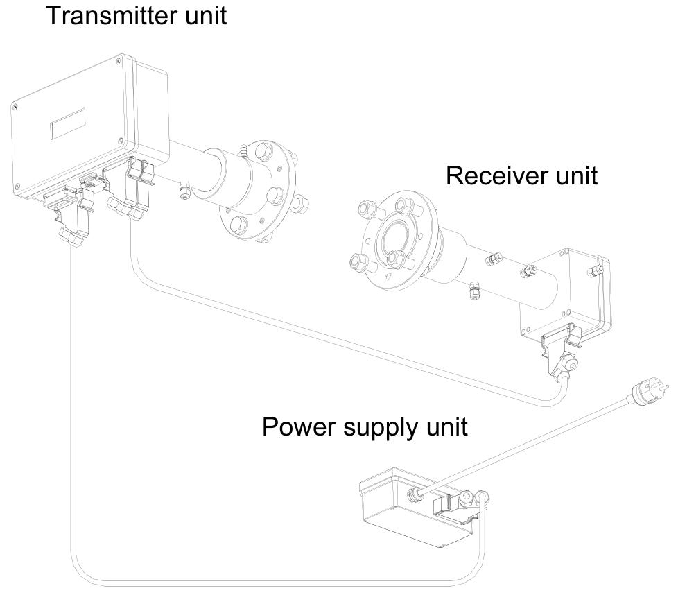
The transmitter unit contains the laser module with a temperature stabilized diode laser, collimating optics, and the main electronics in a coated Aluminum box.
A block diagram of AO2000-LS25 is shown in Figure 1-3.
The receiver electronics is connected with the transmitter electronics with a cable.
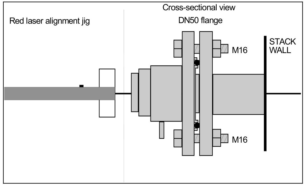
AO2000-LS25 installation
Open the purging.
- YOKOGAWA
- Reliance
- ADVANCED
- SEW
- ProSoft
- WATLOW
- Kongsberg
- FANUC
- VSD
- DCS
- PLC
- man-machine
- Covid-19
- Energy and Gender
- Energy Access
- Renewable Integration
- Energy Subsidies
- Energy and Water
- Net zero emission
- Energy Security
- Critical Minerals
- A-B
- petroleum
- Mine scale
- Sewage treatment
- cement
- architecture
- Industrial information
- New energy
- Automobile market
- electricity
- Construction site
- HIMA
- ABB
- Rockwell
- Schneider Modicon
- Siemens
- xYCOM
- Yaskawa
- Woodward
- BOSCH Rexroth
- MOOG
- General Electric
- American NI
- Rolls-Royce
- CTI
- Honeywell
- EMERSON
- MAN
- GE
- TRICONEX
- Control Wave
- ALSTOM
- AMAT
- STUDER
- KONGSBERG
- MOTOROLA
- DANAHER MOTION
- Bentley
- Galil
- EATON
- MOLEX
- Triconex
- DEIF
- B&W
- ZYGO
- Aerotech
- DANFOSS
- KOLLMORGEN
- Beijer
- Endress+Hauser
- schneider
- Foxboro
- KB
- REXROTH
- YAMAHA
- Johnson
- Westinghouse
- WAGO
- TOSHIBA
- TEKTRONIX
- BENDER
- BMCM
- SMC
- HITACHI
- HIRSCHMANN
- XP POWER
- Baldor
- Meggitt
- SHINKAWA
- Other Brands
- UniOP
- KUKA
- IBA
- Beckhoff
-
ADLINK PCI-7433 - switch value acquisition card Isolated Digital Input Card
-
ADLINK PCI-9112 - 51-12252-0D20 Multi-Function Data Acquisition Card
-
ADLINK NUPRO-A301 REV:1.4 - industrial control motherboard PICMG Full-Size SBC
-
ADLINK 51-18502-0A10 - Frame Grabber Image Acquisition Interface Card
-
ADLINK PCI-7296 - 51-12009-0A50 PCB-I-E-925=6DX1 96-CH Parallel Digital I/O Board
-
ADLINK PCI-8132 GP A2 - Motion Control Card 2-Axis Servo & Stepper Controller
-
ADLINK PCI-7442 - switch quantity card data acquisition card 64-CH Isolated Card
-
ADLINK HPX-13S4 - baseboard PICMG 1.3 Passive Backplane Chassis Baseplate
-
ADLINK NuPRO-590 / NTC-567-ZM-F36 - Single Board Computer PCB-I-E-1853=9L21 Half-Size SBC
-
ADLINK PCIe-8332 - 16-axis plate Motion Control Hardware Card
-
ADLINK NuPRO-775 REV.B1 - motherboard Pentium 4 Full-Size PICMG SBC
-
ADLINK PXI-3920 - Embedded Controller 3U PXI cPCI System Intelligence Board
-
ADLINK PCI-8134 - driver card motion control card 4-Axis Controller Board
-
ADLINK HSL-DI32-M-N-011 / HSL-TB32-M-DIN - Digital Input & Base Module PLC Distributed I/O System
-
ADLINK PCI-6216V-206 / PCI-208V 009 - 16 CH 16bit analog output card
-
ADLINK NuPro-E330 - 51-41805-0A20 PCB Single Board Computer Host Board
-
ADLINK PCI-1622C - Card 8-Port RS-232/422/485 PCI Serial Communication Board
-
ADLINK PCIe-7432 - 51-18402-0A10 Carte PCIe Avec Plage D'Entrée Élevée Isolated DIO Card
-
ADLINK PCI-7250 - PCI Acquisition Card 8-CH Relay Output Isolated DI Card
-
ADLINK PCI-7230 - 32-CH Isolated Digital I/O Card
-
ADLINK PCI-8164 - PCB 4-Axis Motion Controller Card
-
ADLINK PCI-7854 - Collection card High-Speed Link Distributed Motion Controller
-
ADLINK NuPRO-935A/LV - industrial control computer motherboard Full-Size PICMG SBC
-
ADLINK IMB-M40H - motherboard IH61-AA4 1155 LGA1155 Micro-ATX Mainboard
-
ADLINK PCI-7248 - Linhua 51-12006-0A40 48-CH Parallel Digital I/O Card
-
ADLINK HPCI-14S12U - Linhua industrial computer baseboard Passive Backplane
-
ADLINK PCI-8132 Rev.A2 - 2-Axis Servo & Stepper Motion Controller Card
-
ADLINK ACL-8111 - ISA card Multi-Function DAQ Card
-
ADLINK ACL-8111 - ISA card Multi-Function Data Acquisition Board
-
ADLINK PCI-7200 REV.A3 - Digital I/O card 12MB/s High-Speed Parallel Digital I/O
-
ADLINK PCI-7296 REV.A3 - 96-CH High-Density Opto-Isolated DIO Card
-
ADLINK PCI-7434 - 64-CH Isolated Digital Output Card
-
ADLINK M-342 - atx motherboard Industrial PC Mainboard
-
ADLINK NuPRO-935ADV (A) 1.9 - CPU Board Intel Core 2 Quad CPU Q9500 2.83GHz PICMG Board
-
ADLINK NUPRO-935A/DV - motherboard dual network port 51-41802-0A10 CPU Board
-
ADLINK PCI-RTV24 - image capture card Analog Video Frame Grabber Board
-
ADLINK HPX-13S4 - device baseboard PICMG 1.3 Passive Backplane Chassis Baseplate
-
ADLINK PCI-8134A - control card 4-Axis Motion Controller Card
-
ADLINK ACL-7130 REV. B2 - industrial control capture card Isolated Digital I/O Board
-
ADLINK EBP-13E2 - Industrial Backplane Board Passive Backplane Baseboard
-
ADLINK NuPRO-935ADV (A) 1.9 - CPU Board Intel Core 2 Quad CPU Q9500 2.83GHz PICMG SBC
-
ADLINK PCI-8134A - motion control card 4-Axis Pulse-Train Controller Card
-
ADLINK PCI-9112 REV A.1 - Multi Function DA&C Board Data Acquisition Card
-
ADLINK 51-12001-0C20 - Circuit Board Multi-Function Data Acquisition Hardware
-
ADLINK PCI-7300A - 80-CH High-Speed Digital I/O Card
-
ADLINK PCI-7230 - 16-CH Isolated Digital Input Output Card
-
ADLINK DIN-814-GP - motion control module Interface Terminal Block
-
ADLINK NUPRO-A40H - 51-41807-1A20 Industrial Control Motherboard LGA1155
-
ADLINK PCI-7433 rev A2 - Isolated Digital Input Card
-
ADLINK NuPRO-780 - Pentium III 800 512 MB SBC NuPRO780 51-41309-0B2 Single Board Computer
-
ADLINK PCI-7853 / PCI-7854 - Acquisition card High-Speed Link Control Card
-
ADLINK NUPRO-852 / NUPRO-852LV - Industrial motherboard Full-Size PICMG CPU Board
-
ADLINK NuPRO-842LV/P - 51-41360-0B30 Industrial Motherboard Half-Size PICMG SBC
-
ADLINK PCI-FIW64 - 4/2 Channel IEEE1394B Image Capture Card Frame Grabber
-
ADLINK PCI-7851 Rev A1.1 - HSL system card High-Speed Link Master Controller
-
ADLINK PCI-7230 - 51-12003-0A50 card 32-CH Isolated Digital I/O Card
-
ADLINK NuPRO-841REV:1.0 - Industrial CPU Board Mainboard
-
ADLINK NuPRO-841 REV:1.0 - motherboard Industrial Control PC Mainboard
-
ADLINK PCI-8256 - 8-Axis Advanced Motion Control PCI Board
-
ADLINK PCI-6S / PCI6S - Backplane 6-Slot Passive Backplane Board
-
ADLINK PCI-7234 REV B3 - 32-CH Isolated Digital Output PCI Card
-
ADLINK PCI-8213 - HannStar MV-4 51-45003-0b4 Board
-
ADLINK PCI-7233 - 51-12004-0a20 board PCI7233 32-CH Isolated Digital Input Card
-
ADLINK PCI-7851 - 006 51-24003-0B20 High-Speed Link Master Motion Control Card
-
ADLINK PCI-7432 - 64-CH Isolated Digital I/O PCI Cards
-
ADLINK LPCI-3488 - Card Low Profile IEEE-488 GPIB Interface Card
-
ADLINK HPCI14S REV.B1 - industrial control computer base plate Passive Backplane
-
ADLINK NEON-1020 - Industrial camera Smart Camera Vision System
-
ADLINK PCI-7432 - Isolated Digital I/O PCI Card 64-CH
-
ADLINK Pcm-7250+ - 8-Ch Relay Outputs & 8-Ch Isolated DI Module PC/104
-
ADLINK CPCI-7841 - DUAL-PORT ISOLATED CAN INTERFACE CARD CompactPCI
-
ADLINK PCI-3488 / PCI-GPIB - PCI IEEE-488 GPIB Interface Card
-
ADLINK PCI-1711U - Card Multi-Function Data Acquisition Board
-
ADLINK NUPRO-A301 - REV:1.1 1.2 1.4 PICMG Full-Size Single Board Computer
-
Adlink DIN-50S-01 - PLOTECH 51-14024-0A40 50-pin Wiring Terminal Board
-
Chroma 52962 / 58183 - PXI Optical Spectrometer carrier adapter Card
-
ADLINK PCI-6208V - PCI DATA ACQUISITION & RECORDING CARD 8-CH Analog Output
-
ADLINK HSL-DI32-DB-N - Industrial Control Board Distributed Digital Input Module
-
ADLINK HSL-AO4-U - 4-CH HIGH SPEED LINK ANALOG OUTPUT MODULE Distributed I/O
-
ADLINK PCI-7396 - 0050 GP 51-12012-0B20 96-CH High-Speed Digital I/O Card
-
ADLINK NUPRO-935A/DV - 51-41802-0A10 motherboard Industrial CPU Single Board Computer
-
ADLINK PCI-9111 DG - Industrial Acquisition Card Multi-Function DAQ Card
-
ADLINK NuPRO-E315 - industrial computer motherboard Intel Atom SHB SBC
-
ADLINK NUPRO-406 REV:B1 - Industrial Control Motherboard Full-Size PICMG CPU Board
-
ADLINK NuPRO-E330 - motherboard Industrial Control System Host Board PICMG 1.3
-
ADLINK ACL-6128A 103 - 51-11002-1A4 2-CH Isolated Analog Output Card
-
XTRAMUS cPS-H325/AC - POWER SUPPLY NUSTREAMS 600 NETWORK TESTING EQUIPMENT Power Module
-
ADLINK DIN-814P-A4 - 51-14056-0A10 Terminal Block Motion Control Breakout Board
-
ADLINK TB-24P/24-01 - 24-Channel Card Terminal Breakout Board
-
ADLINK PCI-7251 - 51-12008-0A30 PCI7251 8-CH Relay Output Isolated Digital Input Card
-
Basler Electric DECS-250-CN1SN1N Automatic Voltage Regulator for Generator Excitation Control
-
ADLINK CPCI-6860A - 51-31310-OB10 industrial motherboard CompactPCI SBC
-
ADLINK AmITX-SL-G-H110 - 51-7A104-0A30 Mini-ITX Industrial Motherboard
-
ADLINK PXI-2005-003 - CPCI Industrial PC Data Acquisition Card Multi-Function DAQ
-
ADLINK DININ-814M - 51-14032-0A3D SCSI-100P cable connection Interface Terminal Board
-
ADLINK CPCI-3920NA/C2D15/M1G - 3U CompactPCI Intel Core 2 Duo Single Board Computer
-
ADLINK PCIE-8560 - 51-18014-0A20 Communication Card High Speed DAQ
-
ADLINK PCI-C154+ - Motion Control Card 4-axis Motion Controller Board
-
ADLINK PCI-RTV24 - image capture card Analog Video Frame Grabber
-
ADLINK NuPRO-842LV/P - 51-41360-0B30 Industrial Motherboard CPU Board
-
ADLINK cBP-3208/3208R - CPCI Board 3U 8-Slot CompactPCI Backplane
-
ADLINK PCI-8164 - 4-Axis Motion Controller PCI Card 51-12406-0A40
-
ADLINK PCIe-GIE64+ - 4-CH GigE Vision PoE+ Frame Grabber Video Capture Card
-
ADLINK CPCI-6860 / 6860A - CompactPCI Dual Xeon Single Board Computer
-
ADLINK IEC-915GV - REV 1.1 Industrial motherboard CPU Board
-
ADLINK ND-6520 - Technology RS-232 to RS-422RS-485 Converter NuDAM Module
-
ADLINK RTV-24 / PCI-MP4S - 51-12519-1C30 4-Channel Real Time Video Capture Board
-
ADLINK cPCI-6910 / cPCI-6910AM/M1G - cPCI-6910AM/DXL16/M1G/S80G(G)-3120 BOARD CompactPCI SBC
-
ADLINK NUPRO-A40H - Linghua 51-41807-1A30 Industrial Control Computer Motherboard
-
ADLINK USB-3488A - USB to GPIB INTERFACE USB-3488A(G) Controller Module
-
ADLINK PCI-8134A - motion control card 4-Axis Controller Card
-
ADLINK PCI-7432 - Board 32-Channel input / 32-output Isolated Digital I/O PCI Card
-
ADLINK PCI-8134A - 51-12421-0A10 motion controller card tested
-
ADLINK LPCIe-7230 - 32 CH Isolated Input/output Card 2 Interrupts Low Profile PCIe
-
ADLINK NuPRO-E340 - industrial computer motherboard 51-47807-0A30 PICMG 1.3 SHB
-
ADLINK PCI-7434 - High-speed Digital Acquisition Card 64-CH Isolated DO Card
-
ADLINK NuPRO-E330 - 51-41805-0A20 Indsutrial Board SHB Single Board Computer
-
ADLINK PCI-7248 - OPTO-22 48 CHANNEL DIO DIGITAL TTL/DTL I/O 51-12006-0A40 GP
-
ADLINK PCI-8134 - Motion control card 4-Axis Controller Card
-
ADLINK AMP-208C - Movimiento Control Tarjeta 51-12420-1A20 W/Expansión & Breakout
-
ADLINK PCI-8164 - 51-12406-0A40 PCB Board 4-Axis Motion Controller Card
-
ADLINK DIN-68Y-SGII / DIN-68M-J3A - Terminal Board Connector Interface Block
-
ADLINK PCIe-7432 - Technology 51-18402-0A10 PCIe Card With High Input Range
-
ADLINK PCI-8144 / PCI-8144N - Motion control card 4-Axis Stepper Controller Card
-
ADLINK HSL-HUB3/REPEATER - HIGH SPEED LINK EXTENSION MODULES Distributed Hub Module
-
ADLINK ND-6017 - Data Logging + Acquisition 8CH A/D input Mod NuDAM Module
-
ADLINK LPCIe-7250 - data acquisition card Low Profile 8-CH Relay Output Card
-
ADLINK PCI-7432 - I/O card 64-CH Isolated Digital Input Output PCI Card

K-JIANG

Add: Jimei North Road, Jimei District, Xiamen, Fujian, China
Tell:+86-15305925923