
K-WANG


YOKOGAWA AQ2200 Series Multi Application Testing System
Optical sensor module: AQ2200-201/202 (interface module), AQ2200-231/232/241/242 (optical sensor head), AQ2200-211/212/215/221/222 (sensor module)
Other modules: attenuator (AQ2200-311/311A/312/331/332/342), optical switch (AQ2200-411/412/421), BERT (AQ2200-601), optical modulator (AQ2200-621/622), optical receiver (AQ2200-631), etc
YOKOGAWA AQ2200 Series Multi Application Testing System
Core components of the product
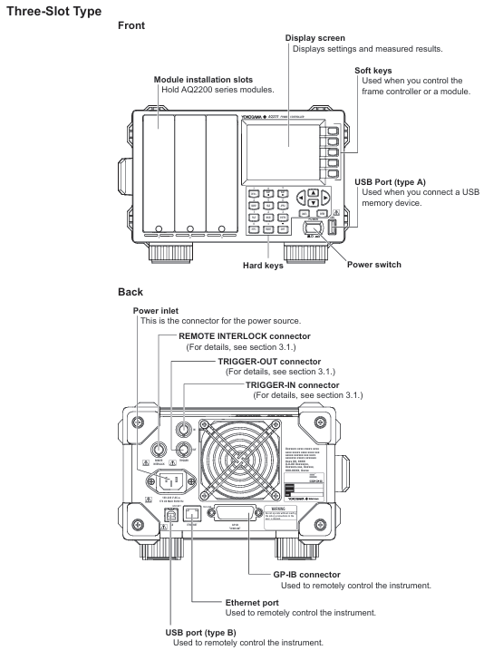
Frame controller: 2 models, responsible for accommodating and controlling modules
AQ2211 (Model 735101): 3 module slots
AQ2212 (Model 735102): 9 module slots
Measurement module: covering the entire process of optical testing, the main types are as follows
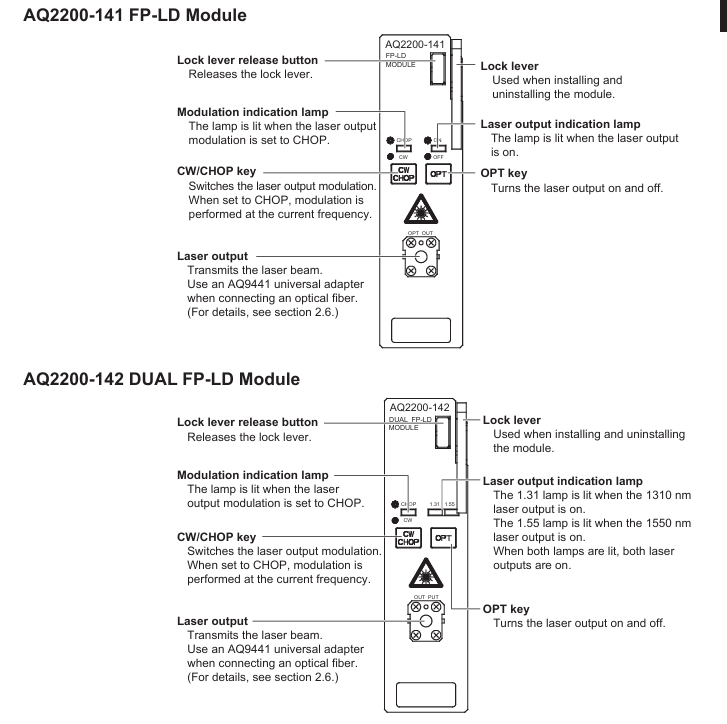
Light source module: AQ2200-111(DFB-LD)、AQ2200-112(LS)、AQ2200-141/142(FP-LD)、AQ2200-131/132(Grid TLS)、AQ2200-136(TLS)
Optical sensor module: AQ2200-201/202 (interface module), AQ2200-231/232/241/242 (optical sensor head), AQ2200-211/212/215/221/222 (sensor module)
Other modules: attenuator (AQ2200-311/311A/312/331/332/342), optical switch (AQ2200-411/412/421), BERT (AQ2200-601), optical modulator (AQ2200-621/622), optical receiver (AQ2200-631), etc
Unpacking inspection and installation preparation
3.1 Open box inspection checklist
Frame controller: Confirm that the model (AQ2211/AQ2212), side nameplate are consistent with the order, and there are no scratches/damages on the appearance
Power cord: Match regional standards according to suffix codes, with the following key parameters
Standard rated voltage of suffix code
- UL/CSA、PSE 125V
04R VDE/Korean 250V
-Q British 250V
-Chinese standard 250V
-Brazilian standard 250V
-Taiwan standard 125V
Standard accessories (not covered by warranty)
Interlocking plug (A1288JA, 1 piece), rubber foot pad (A9088ZM, 1 set)
Printed manuals: IM 735101-01EN (start-up guide), IM 735101-73Z2 (download guide), PIM 113-01Z2 (global contact information), etc
Optional accessories (purchased separately)
Accessory Name Model/Part No. Specification
Blank panel AQ2200-901 1-slot size, covering empty slots
AQ2211 Rack Kit 735182-03 Installation of 1 AQ2211 to EIA Standard Rack Left
AQ2212 Rack Kit 735182-09 Installation of 1 AQ2212 to EIA Standard Rack
3.2 Installation Environment and Requirements
environmental conditions
Temperature: 5-40 ℃ (working), -20~60 ℃ (storage)
Humidity: 20~80% RH (no condensation, consistent with operation and storage)
Altitude: working ≤ 2000m, storage ≤ 3000m
Prohibited environment: direct sunlight, strong magnetic field, high static electricity, corrosive gases, severe vibration
Space requirements: Ensure ventilation and avoid internal overheating
Left and right sides: each ≥ 5cm
Rear: ≥ 10cm (exhaust hole)
Above/Below: Reserve cable connection space
Rack installation steps (kit required)
Disassemble the handles on both sides of the instrument (AQ2211, remove the left side)
Remove the bottom 4 foot pads
Remove the sealing tape at the mounting hole of the rack
Apply new sealing tape to cover the mounting holes of the foot pad/handle
Install the rack kit and secure the instrument to the rack
Core security standards
4.1 Electrical Safety (Warning Level)
Power requirements
Designated power cords must be used, with voltage matching the rated value of the instrument (100-240VAC). Exceeding the maximum voltage of the power cord (such as UL/CSA 125V, VDE 250V) is prohibited
The power plug must be inserted into a three core socket with protective grounding, and the use of ungrounded extension cords is prohibited
grounding protection
Before starting up, it is necessary to connect the protective ground and it is forbidden to cut off the internal/external grounding wire
Check if the grounding and fuse are intact. Do not operate if they are damaged
Operation taboos
Prohibited for use in explosive gas/vapor environments
It is prohibited to dismantle the casing (including high-voltage components inside) without authorization. Only qualified personnel from Yokogawa can repair it
Before connecting external equipment, it is necessary to ground it first. Before touching the circuit, turn off the power and confirm that there is no voltage
4.2 Laser Safety
Laser classification and standards
Module model: Laser classification meets key protection standards
AQ2200-112/131/132 Class 1 IEC 60825-1:2014, 21 CFR 1040.10/11 prohibits direct viewing of laser beams
AQ2200-111/141/142/136 Class 1M IEC 60825-1:2007, 21 CFR 1040.10/11 prohibits the use of optical instruments (magnifying glasses, etc.) for observation at<100mm
Laser unlocking process
Connect the included interlock plug (A1288JA) to the Remote INTERLOCK interface behind the frame controller
Press the SYSTEM key to enter the system screen, move the cursor to Lock, and press ENTER
Enter the default password '1234' and press ENTER
Set Lock to Off and press OK to confirm (laser output can only be turned on after unlocking)
4.3 Environmental Protection and Compliance
WEEE Directive (EEA and UK): Prohibition of mixing household waste, contact local Yokogawa office for disposal
Battery Directive (EEA and UK): Lithium batteries must be collected separately and replaced. Contact the local Yokogawa office for replacement
RoHS compliance: The instrument itself complies with EU RoHS, but if incompatible modules (such as AQ2200-111, AQ2200-131, etc.) are installed, it becomes invalid. The list of incompatible modules can be found in Section 5.1
Taiwan region: Information inquiry on restricted substances for power cord A1100WD: https://tmi.yokogawa.com/support/service-warranty-quality/product-compliance/
Operation process guide
5.1 Module installation and uninstallation
Installation steps
If there is a blank panel in the slot, loosen the screw → slide down to remove the panel
Press the unlock button on the module panel and lift the locking lever
Align with the slot guide rail and slowly insert the module until it is fully seated
Slowly press the lever until you hear a "click" sound (2/3 slot module needs to tighten the bottom fixing screw)
Uninstalling steps
If it is a 2/3 slot module, first loosen the bottom fixing screw
Press the unlock button and gently lift the lever to unlock
Slowly pull out the module (protrude about 1cm, then pull it out by hand)
Hot swappable instructions: Modules can be installed/uninstalled while the frame controller is turned on. If a non SUMMAY/DETAIL screen is displayed during uninstallation, it will automatically switch to these two screens
5.2 Cable Connection
Fiber optic connection
Cleaning the fiber optic end face: Soak the cleaning paper in isopropanol, press and rotate the end face to wipe, then dry it with dry cleaning paper, and finally blow away residual dust with compressed air
Connection rule: The ANGLED PC ONLY interface is only connected to APC type fiber optic cables and is prohibited from connecting other types (to avoid damaging the plug)
Connector adapter: such as AQ9441 (for FP-LD module), AQ9335C (for sensor module), align the guide pin/hole connection according to the manual steps, and lock the lever
electrical connection
Coaxial cable: used for modules such as BERT and optical modulators. Before connecting, confirm that the signal output is turned off and tighten the connector with a torque of 0.9N-m
Power cord: Confirm that the instrument switch is turned off, connect it to a three pin grounded socket, and ensure that the voltage matches the rated value
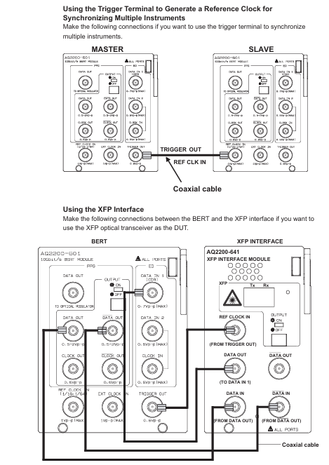
Key module connection example (BER test)
BERT module (AQ2200-601) DATA OUT → Optical modulator (AQ2200-621/622) DATA IN
Light modulator LD IN → Light source module (AQ2200-111 PMF type) laser output
Optical modulator OPT OUT → DUT → Optical receiver (AQ2200-631) OPT IN
Optical receiver DATA OUT → BERT module DATA IN 1 (CDR)
5.3 Startup and Screen Operation
boot process
Confirm that the power connection is correct, press the POWER switch on the front panel of the frame controller
The instrument automatically performs self check, and after passing the test, it displays the SUMMAY screen (global module information) or Detail screen (individual module details)
Preheating requirement: To ensure measurement accuracy, it is recommended to preheat for at least 1 hour after turning on the machine
screen operation
SUMMAY screen: The blue background represents the "current module" (modifiable parameters), the light blue background represents the "current parameters", and the empty slot displays "NO MODULE"
Detail screen: The top displays the current module slot, allowing you to view/modify all parameters of the module (such as wavelength and attenuation values)
Hard key function (key buttons)
Hard key function keyboard mode corresponds to numbers
Switch to Detail Screen 7
SLOT ◄/► Switch current control module 8/9
Switch to SUMMAY screen 4
HOLD pauses screen updates, press again to resume 5
SYSTEM: Enter the system settings screen (date, password, etc.) 3
Maintenance and troubleshooting
6.1 Daily Maintenance
Cleaning requirements
Body: Wipe with a dry soft cloth after power failure. Do not use chemicals such as benzene or diluents (to avoid discoloration/deformation)
Optical interface: Clean with isopropanol and cleaning paper, and only use compressed air to remove dust from the sensitive surface of the sensor head (wiping is prohibited)
Electrical interface: Use compressed air to blow away dust, without using interface cover protective cap/terminal
Regularly replace parts
Suggested replacement cycle note for part name
Cooling fan for 40000 hours to ensure ventilation and avoid internal overheating
Lithium batteries will also be consumed even when the instrument is powered off for 3 years
ATTN module shutter 150000 times suitable for AQ2200-311/311A/312/331/332
LCD backlight for 30000 hours (default brightness 5) needs to be replaced when the brightness drops to half
Calibration requirements
Conventional module: It is recommended to calibrate once a year
AQ2200-111 (DFB-LD): Calibrate every 6 months due to semiconductor characteristics
Calibration method: Contact the Yokogawa dealer to adjust the parameters simultaneously
6.2 Troubleshooting
Common Problems and Solutions
Possible causes and solutions for the problem phenomenon
The instrument cannot be turned on. The power cord is not properly connected and the voltage does not match. Check the power cord connection and confirm that the voltage is between 90-264VAC
Laser lock without output, interlock plug not connected, unlock according to the process (password 1234)
PPG-ED cannot synchronize. The cable is not properly connected and the PPG and ED parameters do not match. Check the cable and confirm that the pattern and PRBS length of PPG and ED are consistent
OE displays LOS alarm for fiber not connected and low input power. Check the fiber connection and add an optical amplifier to increase power
Key error codes
Error code description and solution measures
1014 frame controller and module firmware version do not match. Update firmware to the latest version (contact dealer for information)
1100 laser output locking connection interlock plug, unlocking laser output
1266 Input power exceeds the maximum limit and reduces input power to the specified range (refer to module parameters)
Fault contact preparation: The instrument model, serial number, firmware version, operating steps at the time of the fault, and screen display need to be provided
Firmware update
7.1 Frame Controller Firmware Update
preparation
Download the latest firmware, rename it to "aq221xlz. bin", and place it in the USB root directory
Disconnect all external devices and only retain USB (direct connection, not through Hub)
Update steps
Turn off the power of the frame controller and plug in the USB
Press and hold the soft key at the top of the front panel, while pressing the POWER switch to turn on the device
The screen displays the update progress, and after completion, it prompts "Flash Update Complete", and the instrument automatically restarts
After restarting, remove the USB and confirm the version by pressing SYSTEM → Soft Version View
7.2 Module firmware update
preparation
Download the latest firmware of the module and place it in the "module" folder on the USB (without renaming)
Insert the USB into the USB Type A port on the front panel of the frame controller
Update steps
Press the SYSTEM key → move the cursor to "Module Update" → press ENTER
Use the arrow keys to select the module that needs to be updated (the checkbox turns black) → Press the 'Update Execut' soft key
Display update status (Executing/Complete/Failed), prompt "Please Restart System" after completion
Restart the frame controller and confirm that the module version update is successful
- YOKOGAWA
- Reliance
- ADVANCED
- SEW
- ProSoft
- WATLOW
- Kongsberg
- FANUC
- VSD
- DCS
- PLC
- man-machine
- Covid-19
- Energy and Gender
- Energy Access
- Renewable Integration
- Energy Subsidies
- Energy and Water
- Net zero emission
- Energy Security
- Critical Minerals
- A-B
- petroleum
- Mine scale
- Sewage treatment
- cement
- architecture
- Industrial information
- New energy
- Automobile market
- electricity
- Construction site
- HIMA
- ABB
- Rockwell
- Schneider Modicon
- Siemens
- xYCOM
- Yaskawa
- Woodward
- BOSCH Rexroth
- MOOG
- General Electric
- American NI
- Rolls-Royce
- CTI
- Honeywell
- EMERSON
- MAN
- GE
- TRICONEX
- Control Wave
- ALSTOM
- AMAT
- STUDER
- KONGSBERG
- MOTOROLA
- DANAHER MOTION
- Bentley
- Galil
- EATON
- MOLEX
- Triconex
- DEIF
- B&W
- ZYGO
- Aerotech
- DANFOSS
- KOLLMORGEN
- Beijer
- Endress+Hauser
- schneider
- Foxboro
- KB
- REXROTH
- YAMAHA
- Johnson
- Westinghouse
- WAGO
- TOSHIBA
- TEKTRONIX
- BENDER
- BMCM
- SMC
- HITACHI
- HIRSCHMANN
- XP POWER
- Baldor
- Meggitt
- SHINKAWA
- Other Brands
- UniOP
- KUKA
- IBA
- Beckhoff
-
LTI SC52.0040.0012.0000.0 - Servo Drive
-
Lti SC52.0040.0012.0000.0 - Servo Drive
-
Milton Industries LTI Tool By Milton LT1240 - 1/2" Drive Lugnut Remover
-
LTi Drives SO84.200.P030.0000.0-W - Servo Spindle Drive
-
LTI DRIVES LSP08-035-320-30-B0R1PY170 - Servo Motor
-
LTI DRIVES SE84.200.SC00.0001.0-W - Servo Drive
-
Lust CDE34.005.W2.2 - Lti Drives Controller
-
LTi SO84.012.0030.0011.2 - ServoOne Servo Drive
-
LTi Drives SO CM-P.0010.11.00.0 - Servo Drive Controller
-
LTi CDE34.017.W3.0 - Servo Drive
-
LTI Drives CDB32.004, C2.0,SH - Positioning Controller
-
LUST CM-CAN1 - LTi DRIVES Communication Module
-
LTi SO84.012.1030.0000.2 - Servo Drive
-
LTI MOOG CDE54.044 - PITCHMASTER FREQUENCY CONVERTER 181-01019
-
MOOG LTI 181-01019 CDE54.044 - PITCHMASTER FREQUENCY CONVERTER
-
Lust LTi Drives CDE34.010,D2.0 - Servo Drive Controller
-
LTI SO84.032.0003.0101.2 - Servo Drive
-
Seagate 9CC132-302 Harris LTI-CS IRT-34-0021-01 - Hard Drive 160GB
-
LTI SO84.032.0003.0001.2 - Servo Drive
-
LTI SO24.007.0070.0000.1 - SERVO CONTROLLER
-
LTi drive CDA32.003.C3.0.H05-01.PC1 - Servo Drive
-
LTI SO84.016.0030.0000.2 - SERVO CONTROLLER
-
LUST LTI CD A34.008,W1.4, BR - SERVO DRIVE
-
MOOG LTI 181-01019 CDE54.044 - PITCHMASTER FREQUENCY CONVERTER
-
LTI MOOG 181-01019 - PITCH Master Servo Drive CDE54.044
-
LTI SERVO ONE SO84.045.0030.0001.2-W - Drive
-
LUST LTi SO84.032.0040.0000.2 - SERVO ONE DRIVE
-
LTi Drives LSH-074-2-30-3 20/T1,G6.1M - SERVO MOTOR
-
LTI SO84.016.0000.0101.2 - servo drive
-
LTI SA54.0550.0033.0000.0 - Servo Drive
-
LTI SA54.0550.0033.0000.0 - Servo Drive
-
LTI LT 4850 - 3/8" Drive 3-Pc Twist Socket Transmission Drain Plug Removal System
-
LTI Tools LT4400-30 Lock Technology - 3/4" Twist Socket 1/2" Drive Lugnut Remover
-
LTI Tools LT-1400C - 1/2 Drive Wheel Torque Extension Tool
-
LTI Tools LT1250 - 1/2" Drive Dual Sided Socket Lug Nut Remover Tool
-
LTI SO84.032.0003.0101.2 - Servo Drive
-
LTI MOOG 181-01019 - PITCH Master Servo Drive CDE54.044
-
MOOG LTI 181-01019 CDE54.044 - PITCHMASTER FREQUENCY CONVERTER
-
MOOG LTI 181-01019 CDE54.044 - PITCHMASTER FREQUENCY CONVERTER
-
MOOG LTI 181-01019 CDE54.044 - PITCHMASTER FREQUENCY CONVERTER
-
LTI SA54.0550.0033.0000.0 - Servo Drive
-
LTI Tools LT-4800 - 7 Piece Twist Socket 3/8" Drive Oil Drain Plug Removal Set
-
LTI SA54.0550.0033.0000.0 - Servo Drive
-
LTI Drive SO24.007.00300000.0 - Servo Drive
-
LTI TOOLS LTI 1400-I - Drive Wheel Torque Extension
-
LTI Tools LT4400-3 - 3/4" 19mm Twist Socket 1/2" Drive Lugnut
-
LTI TOOLS LTI 1400-BB - Drive Wheel Torque Extension
-
LTI SO84.032.0003.0101.2 - Servo Drive
-
LTI Tools LT-4512 - 3/8" Drive 12mm Twist Socket
-
LTI MOTION Luster SO84.032.0003.0001.2 - Servo Drive
-
LTI Tool By Milton LT1600P - 1" Drive Torx Stick
-
LTI Lust VF1424L,HF,OP2,S56 - Variable Frequency Drive
-
LUST CDA32.004,C1.4,H08,B0 - SERVO DFRIVE CM-CAN1 Module
-
LTI SO84.045.0002.0001.2-W - Drive
-
LTI Lust VF1404M,C9,PT1,BR1 - Inverter Type VF1404M
-
LTI SA54.0550.0033.0000.0 - Servo Drive
-
LTI Tools LT-1400C - 1/2" Drive Wheel Torque Extension
-
Lust LTI DRiVES CDA32.006, C3.0, H09 - Variateur De Fr茅quence Frequency Inverter
-
LTI MOOG CDE54.044 - PITCH master SERVO DRIVE
-
LTI MOOG CDE54.044 - PITCH master SERVO DRIVE
-
LTI SO84.143.0020.0101.2-W - servo drive
-
LTI MOTION SC34.0200.0011.0000.0 - Servo drives
-
LTI SO84.032.0003.0001.2 - Servo Drive
-
LTI DRIVES GmbH MS100 - Assembly Set Mounting Kit
-
LTI SO84.032.0003.0001.2 - Servo Drive
-
LTI SO84.032.0003.0001.2 - Servo Drive
-
LTI MOTION SO84.032.0003.0101.2 - servo drive
-
LTI SO84.032.0003.0101.2 - Servo Drive
-
LTI MOOG CDE54.044 - PITCH master SERVO DRIVE
-
LTI MOTION CDE32.004.C2.4 - Servo drives
-
LTI CDD34.032锛學x.x锛孊R锛孭C1 - Servo Drive
-
Lust LTI DRiVES CDA32.006, C3.0, H09 - Inversor De Frecuencia Frequency Inverter
-
Lust SO84.008.0030.1000.0 - Servo One LTi Drive
-
LTI MOTION SO84.032.0003.0101.2 - Servo drives
-
LUST LTi CDA32.004,C1.4 - SERVO DRIVE
-
LTI MOOG CDE54.044 - PITCH Master SERVO DRIVE
-
LTI KEBA CDB32.004 C2.7, SH - PN: 08673530 Frequency Inverter
-
LTI Tools LT-1400C - 1/2" Drive Wheel Torque Extension
-
LTI LT1400-E - 1/2" Drive Wheel Torque Extension
-
LTI MOOG 181-01019 - PITCH master SERVO DRIVE CDE54.044
-
LTI LSN-097-0510-30-560/T1 - Actuator Motor
-
LTI Tools LT 4800 - 7 Piece 3/8" Drive Twist Socket Oil Drain Plug Removal System
-
LTI DRIVES GmbH MS100 - MONTAGESET Assembly Set Mounting Kit
-
Lti SC52.0040.0012.0000.0 - Servo Drive
-
LTI DRIVES GmbH MS100 - Juego De Montaje Assembly Set Mounting Kit
-
LTi DSM4-14.2-21R83-200 - Drives servomoteur Servo Motor
-
MOOG CDE 54.044.GDA - Pitch Master Industrielle Turbine Lti Drive
-
LTI SO24.004.0030.1000.0 - Servo Drive Controller
-
Lti MOOG CDE54.044 - Pitch Master Servo Drive
-
Lust LTI DRiVES CDA32.006, C3.0, H09 - Inverter
-
LTI MOTION GMBH CDB34.006,W3.0,PC1,H39 - Frequency inverter
-
LTI SO84.032.0003.0001.2 - Servo Drive
-
MOOG CDE 54.044.D - Pitch Master Industrielle Turbine Lti Drive
-
LTI TOOLS LT-1460 - 1/2" DRIVE WHEEL TORQUE EXTENSION KIT 5 PIECE SET
-
Lust Cdb32.003, C2.4 - Lti Drives Servoregulador Frecuencia Servo Controller Inverter
-
Lust LTI DRIVES CDA32.006, C3.0, H09 - Frequency Inverter
-
Lust Lti SO82.004.0030.0000.2 - Servo Drive
-
LTI MOTION SC34.0200.0011.0000.0-SL - Servo drives
-
LTI MOTION SA54.0075.0033.0000.0 - Servo drives
-
LTI MOTION SC32.0075.1011.0000.0 - Servo drives
-
LTI Servo-One Junior SO22.006.0080.1000.0 - Servo Controller Servoregler
-
LUST CDA32.004, C1.4, H08, B0 - Servo Drive & LTI CM-CAN1 Module
-
LTI DRIVES LSP08-035-320-30-B0R1PY170 - Servo Motor
-
LUST LTI CDA32.004,C1.4.H08.B0 - SERVO CONTROLLER DRIVES
-
LUST LTi DRiVES CDS44.072LC1.2 - Servo Drive
-
Lti Servo-One Junior SO22.006.0082.1000.0 - Servo Controller Servoregler
-
LUST CDA32.008,C2.0,HF - Lti DRIVES Spindle Drive Inverter
-
LTI SO22.003.0082.0000.0 - Servo Drives One junior Servo Controller Servoregler
-
Lust Lti Drives CM-CAN1 - Communication Module
-
LUST Lti Drives Vf1202s, G8, I6 - Frequency Inverter Drive
-
LTI DRIVES BR-090.03.540.UR.H38 - Bremswiderstand Brake Resistor
-
LTi DRIVES PM-E40.2DRA054P - Wind Turbine Pitch Control Inverter
-
LTi Drives GmbH br-110.01.540-UR - Brake Resistor
-
LTI Drives LSN-097-0960-30-0560/T1,S4,B - Servo Motor
-
LUST CDA34.006.C2.0 - LTI Drives Servoregler
-
LUST LTI DRIVES SERVO ONE JUNIOR SO24.002.0020.0000.1 - Servo Drive Controller
-
LTI MOTION SO84.032.0003.0001.2 - Servo drives
-
LTI DDTD750V2-120 - IBOP ACTUATOR CYLINDER FOR TOP DRIVE
-
LTI CDE32.004, C2.4 - SERVO DRIVE
-
LUST LTI DRIVES CDD34.017 W3.4PC1 - Servo Drive Controller
-
LTI CDA3208,C3,0,HF - AC SERVO DRIVE
-
LUST LTI DRIVES LSH-074-3-30-560/T1,G6.1S - SERVO MOTOR
-
LUST Lti CDB32.004.C2.4.SH - AC Servo Drive
-
LTi CDA32.006, C3.0, H09 - Servo Drive
-
LTI SO22.003.0010.0000.0 - Servo Drive Servo one junior Servoregler Controller
-
LTi Drives DSM4-14.2-21R83-200 - Servo Motor
-
LUST Lti Drives Lsh-097-1-30-560/T1, 1R - Servomotor
-
LTI 1237 - 7 Piece 1/2" Drive Flip Socket Set

K-JIANG

Add: Jimei North Road, Jimei District, Xiamen, Fujian, China
Tell:+86-15305925923