
K-WANG


YOKOGAWA AQ6150B/AQ6151B Optical Wavelength Meter
YOKOGAWA AQ6150B/AQ6151B Optical Wavelength Meter
Overview
The "Beginner's Guide" (6th Edition, document number IM AQ6150B-02EN) for YOKOGAWA AQ6150B/AQ6151B optical wavelength meters introduces the core functions of the two instruments (measuring light source optical characteristics, supporting single wavelength/multi wavelength detection), preparation before use (packaging content inspection, indoor installation requirements, power connection and power on/off process), basic operations (panel button/mouse/keyboard operation, parameter and string input), maintenance points (firmware updates, daily cleaning, component replacement cycles), and key specifications (wavelength range 900-1700nm, wavelength accuracy up to ± 0.2ppm, etc.), while emphasizing safety precautions (anti electric shock, anti laser eye injury). And provided user registration, technical support contact information, and access to relevant manuals.
Preparation before use
1. Packaging content inspection
After unboxing, it is necessary to confirm that the host, standard accessories, and optional accessories are complete. The standard accessories are as follows (optional accessories need to be purchased separately):
Category, Part Name, Model/Part Number, Quantity, Key Explanation
Host AQ6150B/AQ6151B Host -1 Confirm that the back nameplate model is consistent with the order, and record the instrument number (to be provided when contacting the dealer)
Standard Attachment - Power Supply Cord A1006WD (UL/CSA) 1 needs to be matched with regional standards, such as A1064WD for China and A1009WD for Europe; Suffix - Y without power cord
Standard attachment - Other rubber foot pads A9088ZM 2 sheets A9088ZM includes 2 foot pads for fixing instruments to prevent sliding
Standard attachments - Introduction to manuals, IM AQ6150B-02EN, etc. 1 copy each, including download request document, Chinese document, European Language Safety Manual, and global contact information list
Optional accessories - connector AQ9441 connector adapter (FC) AQ9441-FC - for optical input interface, also available in SC model (AQ9441-SC)
2. Instrument installation requirements
Installation environment: For indoor use only, avoid flammable and explosive environments, high vibration/high dust areas, direct sunlight or near heat sources
Placement requirements: Horizontal and stable tabletop, anti tilt; A ventilation gap of ≥ 20cm should be reserved between the bottom air inlet and the back air outlet to prevent internal overheating
Anti impact: When handling, turn off the power, disconnect all cables, and hold the handles on both sides with both hands to avoid falling (to prevent damage to the internal interferometer)
Rack installation: A separate rack kit (EIA standard 751535-E3, JIS standard 751535-J3) needs to be purchased, and the bottom should be supported and not obstruct the ventilation holes during installation
3. Power connection and power on/off
Power specifications: Rated voltage 100-240V AC, frequency 50/60Hz, maximum power consumption ≈ 100VA; allowable voltage range 90-264V AC, frequency 48-63Hz
Power on/off process:
Connect the power cord in the shutdown state (grounded, using a three pin socket);
Turn on the back MAIN POWER switch, and the front POWER light will turn orange;
After waiting for a few seconds, press the front POWER switch, the light turns green, and the instrument starts initialization (displaying STEP 1/6 to STEP 6/6);
To shut down, first press the front POWER switch, confirm the pop-up window, and then click "Yes". After the POWER light turns orange, turn off the MAIN POWER switch.
Basic Operations
1. Control method
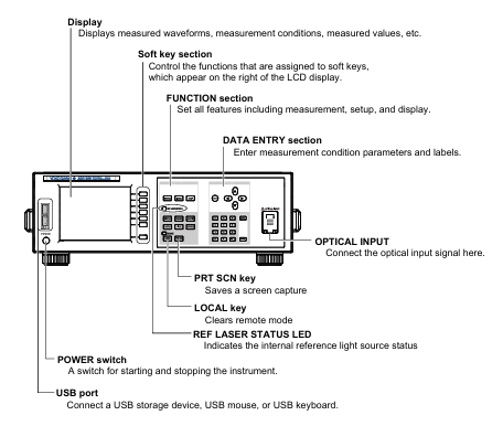
Panel button operation:
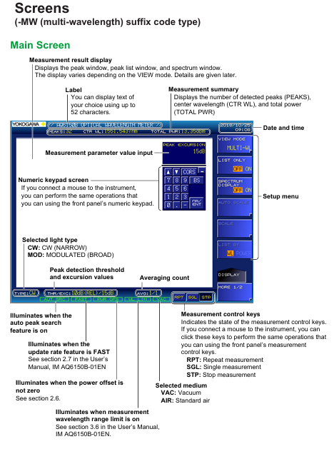
Function area: including measurement control keys (REPEAT/SINGLE/STOP), function keys (PLAY/SEARCH/SETUP, etc.), and auxiliary keys (PRT SCN/LOCAL);
DATA ENTRY: Enter parameters using the numeric keypad, arrow keys, COARSE key, delete with BACK SPACE key, and confirm with ENTER key.
Mouse/keyboard operation:
Mouse: Left click=panel button operation, right-click to display function key list, can execute menu selection;
External keyboard: supports shortcut key mapping (such as [SHIFT]+[F1] to start display settings, [ALT]+[N] to switch COARSE/FINE mode), can input file names, labels, etc.
2. Core operating procedures
Parameter input:
Numerical input: Press the soft key with parameters, enter through the numeric keypad or arrow keys to adjust, confirm with the ENTER key (automatically reset to the nearest valid value if it exceeds the range);
String input: When entering a label/file name, a on-screen keyboard pops up, and characters can be selected using arrow keys. It supports cursor movement, insertion/deletion operations.
Fiber optic connection:
Clean the fiber end face: Use NTT-AT special cleaning agent, press and rotate to wipe (ensure no dust, avoid damaging the instrument optical interface);
Connecting the instrument: Connect the fiber optic cable to the "Optical INPUT" interface. If an attenuator/amplifier is required, it should be connected in series between the light source and the instrument, and the power offset (POWER OFFSET) should be set to match the actual power.
Maintenance and Calibration
1. Firmware update
Update purpose: To enhance the functionality and usability of the instrument, the latest firmware (. UPD format) needs to be downloaded from the Yokogawa official website;
Update method:
USB update: Create an "Update" folder in the USB root directory, place the firmware file, and execute it through System → System Information → Update (USB);
Network update: Connect to the PC via Ethernet, copy the firmware to the internal Update directory of the instrument, and execute it through Update (NETWORK);
Attention: Do not turn off the power during the update. The instrument will automatically restart after the update, and the settings data will be initialized (backup is required in advance).
2. Daily maintenance
External cleaning: After power off, wipe the body and operation panel with a dry cloth, and prohibit chemicals such as benzene and diluents (to avoid discoloration and deformation);
Optical interface cleaning:
Connector adapter: Insert a rod-shaped cleaning agent into the optical interface and rotate it for cleaning;
Fiber end face: After power off, remove the adapter and wipe the plug end face with an alcohol swab (use a new swab each time).
3. Component replacement cycle
Key Explanation of Component Name Replacement Cycle/Service Life
LCD backlight ≈ 50000 hours (normal use) may experience brightness degradation after reaching its lifespan, and dealers need to be contacted for replacement
Internal reference light source (He Ne laser) ≈ 40000 hours (recommended to replace 30000 hours). When the lifespan is approaching, the REF Laser STATION LED turns orange, and when it malfunctions, it turns red (needs to be replaced immediately)
Optical input internal plug ≈ 2 years (normal use) Frequent plugging and unplugging may cause wear and affect measurement accuracy
The cooling fan should be replaced regularly every 7 years to prevent the instrument from overheating
Backup battery (lithium battery) for 7 years to store settings data, to be replaced promptly upon expiration
Safety and Compliance
1. Safety Warning
Warning (risk of fatal/serious injury):
Laser or instrument optical input interfaces that cannot be directly measured (may cause blindness);
Grounding must be used, and ungrounded extension cords are prohibited;
Do not use in flammable and explosive environments, and do not disassemble the instrument by yourself (there is high pressure inside).
CAUTION (Minor Injury/Equipment Damage Risk):
The instrument is a Class A industrial equipment, which may cause radio interference when used in residential areas and needs to be resolved by the user themselves;
Avoid strong light with an input power of ≥+18dBm (which may damage internal optical components), and connect the light source after the instrument is started.
2. Compliance requirements
Environmental compliance: Complies with the EU WEEE Directive (must not be mixed with household waste for disposal) and the Battery Directive (lithium batteries must be recycled separately);
Laser compliance: The built-in laser light source is Class 1 (compliant with IEC 60825-1:2014), with a maximum laser power of 5mW for AQ6150B and 15mW for AQ6151B, both with a wavelength of 633nm;
Regional compliance: Taiwan region needs to check the restricted substance information of power cord (A1100WD) (designated link on the official website).
Key specification parameters
The core specifications of AQ6150B/AQ6151B are as follows (specific to model and suffix):
Specification category specific parameters
Applicable to fiber optic SM (ITU-T G.652)
Wavelength range standard type 1270-1650nm, extended type 1200-1700nm, wide range type 900-1700nm
The wavelength accuracy of AQ6150B is up to ± 0.7ppm, and AQ6151B is up to ± 0.2ppm (1550nm, normal update rate)
Minimum power range -40dBm (1200-1600nm), maximum+10dBm, safe input power+18dBm
Power accuracy ± 0.5dB (1550nm, -10dBm)
Measurement time normal update rate ≤ 0.3s, fast update rate ≤ 0.2s
Display device 5.7-inch color LCD (resolution 640 × 480 pixels)
Interface GP-IB, Ethernet, USB (2 in front and 2 in back), VGA output
The working environment temperature is 5-35 ℃, and the humidity is 20-85% RH (without condensation); Performance guarantee temperature 10-30 ℃


- YOKOGAWA
- Reliance
- ADVANCED
- SEW
- ProSoft
- WATLOW
- Kongsberg
- FANUC
- VSD
- DCS
- PLC
- man-machine
- Covid-19
- Energy and Gender
- Energy Access
- Renewable Integration
- Energy Subsidies
- Energy and Water
- Net zero emission
- Energy Security
- Critical Minerals
- A-B
- petroleum
- Mine scale
- Sewage treatment
- cement
- architecture
- Industrial information
- New energy
- Automobile market
- electricity
- Construction site
- HIMA
- ABB
- Rockwell
- Schneider Modicon
- Siemens
- xYCOM
- Yaskawa
- Woodward
- BOSCH Rexroth
- MOOG
- General Electric
- American NI
- Rolls-Royce
- CTI
- Honeywell
- EMERSON
- MAN
- GE
- TRICONEX
- Control Wave
- ALSTOM
- AMAT
- STUDER
- KONGSBERG
- MOTOROLA
- DANAHER MOTION
- Bentley
- Galil
- EATON
- MOLEX
- Triconex
- DEIF
- B&W
- ZYGO
- Aerotech
- DANFOSS
- KOLLMORGEN
- Beijer
- Endress+Hauser
- schneider
- Foxboro
- KB
- REXROTH
- YAMAHA
- Johnson
- Westinghouse
- WAGO
- TOSHIBA
- TEKTRONIX
- BENDER
- BMCM
- SMC
- HITACHI
- HIRSCHMANN
- XP POWER
- Baldor
- Meggitt
- SHINKAWA
- Other Brands
- UniOP
- KUKA
- IBA
- Beckhoff
-
LTI SC52.0040.0012.0000.0 - Servo Drive
-
Lti SC52.0040.0012.0000.0 - Servo Drive
-
Milton Industries LTI Tool By Milton LT1240 - 1/2" Drive Lugnut Remover
-
LTi Drives SO84.200.P030.0000.0-W - Servo Spindle Drive
-
LTI DRIVES LSP08-035-320-30-B0R1PY170 - Servo Motor
-
LTI DRIVES SE84.200.SC00.0001.0-W - Servo Drive
-
Lust CDE34.005.W2.2 - Lti Drives Controller
-
LTi SO84.012.0030.0011.2 - ServoOne Servo Drive
-
LTi Drives SO CM-P.0010.11.00.0 - Servo Drive Controller
-
LTi CDE34.017.W3.0 - Servo Drive
-
LTI Drives CDB32.004, C2.0,SH - Positioning Controller
-
LUST CM-CAN1 - LTi DRIVES Communication Module
-
LTi SO84.012.1030.0000.2 - Servo Drive
-
LTI MOOG CDE54.044 - PITCHMASTER FREQUENCY CONVERTER 181-01019
-
MOOG LTI 181-01019 CDE54.044 - PITCHMASTER FREQUENCY CONVERTER
-
Lust LTi Drives CDE34.010,D2.0 - Servo Drive Controller
-
LTI SO84.032.0003.0101.2 - Servo Drive
-
Seagate 9CC132-302 Harris LTI-CS IRT-34-0021-01 - Hard Drive 160GB
-
LTI SO84.032.0003.0001.2 - Servo Drive
-
LTI SO24.007.0070.0000.1 - SERVO CONTROLLER
-
LTi drive CDA32.003.C3.0.H05-01.PC1 - Servo Drive
-
LTI SO84.016.0030.0000.2 - SERVO CONTROLLER
-
LUST LTI CD A34.008,W1.4, BR - SERVO DRIVE
-
MOOG LTI 181-01019 CDE54.044 - PITCHMASTER FREQUENCY CONVERTER
-
LTI MOOG 181-01019 - PITCH Master Servo Drive CDE54.044
-
LTI SERVO ONE SO84.045.0030.0001.2-W - Drive
-
LUST LTi SO84.032.0040.0000.2 - SERVO ONE DRIVE
-
LTi Drives LSH-074-2-30-3 20/T1,G6.1M - SERVO MOTOR
-
LTI SO84.016.0000.0101.2 - servo drive
-
LTI SA54.0550.0033.0000.0 - Servo Drive
-
LTI SA54.0550.0033.0000.0 - Servo Drive
-
LTI LT 4850 - 3/8" Drive 3-Pc Twist Socket Transmission Drain Plug Removal System
-
LTI Tools LT4400-30 Lock Technology - 3/4" Twist Socket 1/2" Drive Lugnut Remover
-
LTI Tools LT-1400C - 1/2 Drive Wheel Torque Extension Tool
-
LTI Tools LT1250 - 1/2" Drive Dual Sided Socket Lug Nut Remover Tool
-
LTI SO84.032.0003.0101.2 - Servo Drive
-
LTI MOOG 181-01019 - PITCH Master Servo Drive CDE54.044
-
MOOG LTI 181-01019 CDE54.044 - PITCHMASTER FREQUENCY CONVERTER
-
MOOG LTI 181-01019 CDE54.044 - PITCHMASTER FREQUENCY CONVERTER
-
MOOG LTI 181-01019 CDE54.044 - PITCHMASTER FREQUENCY CONVERTER
-
LTI SA54.0550.0033.0000.0 - Servo Drive
-
LTI Tools LT-4800 - 7 Piece Twist Socket 3/8" Drive Oil Drain Plug Removal Set
-
LTI SA54.0550.0033.0000.0 - Servo Drive
-
LTI Drive SO24.007.00300000.0 - Servo Drive
-
LTI TOOLS LTI 1400-I - Drive Wheel Torque Extension
-
LTI Tools LT4400-3 - 3/4" 19mm Twist Socket 1/2" Drive Lugnut
-
LTI TOOLS LTI 1400-BB - Drive Wheel Torque Extension
-
LTI SO84.032.0003.0101.2 - Servo Drive
-
LTI Tools LT-4512 - 3/8" Drive 12mm Twist Socket
-
LTI MOTION Luster SO84.032.0003.0001.2 - Servo Drive
-
LTI Tool By Milton LT1600P - 1" Drive Torx Stick
-
LTI Lust VF1424L,HF,OP2,S56 - Variable Frequency Drive
-
LUST CDA32.004,C1.4,H08,B0 - SERVO DFRIVE CM-CAN1 Module
-
LTI SO84.045.0002.0001.2-W - Drive
-
LTI Lust VF1404M,C9,PT1,BR1 - Inverter Type VF1404M
-
LTI SA54.0550.0033.0000.0 - Servo Drive
-
LTI Tools LT-1400C - 1/2" Drive Wheel Torque Extension
-
Lust LTI DRiVES CDA32.006, C3.0, H09 - Variateur De Fr茅quence Frequency Inverter
-
LTI MOOG CDE54.044 - PITCH master SERVO DRIVE
-
LTI MOOG CDE54.044 - PITCH master SERVO DRIVE
-
LTI SO84.143.0020.0101.2-W - servo drive
-
LTI MOTION SC34.0200.0011.0000.0 - Servo drives
-
LTI SO84.032.0003.0001.2 - Servo Drive
-
LTI DRIVES GmbH MS100 - Assembly Set Mounting Kit
-
LTI SO84.032.0003.0001.2 - Servo Drive
-
LTI SO84.032.0003.0001.2 - Servo Drive
-
LTI MOTION SO84.032.0003.0101.2 - servo drive
-
LTI SO84.032.0003.0101.2 - Servo Drive
-
LTI MOOG CDE54.044 - PITCH master SERVO DRIVE
-
LTI MOTION CDE32.004.C2.4 - Servo drives
-
LTI CDD34.032锛學x.x锛孊R锛孭C1 - Servo Drive
-
Lust LTI DRiVES CDA32.006, C3.0, H09 - Inversor De Frecuencia Frequency Inverter
-
Lust SO84.008.0030.1000.0 - Servo One LTi Drive
-
LTI MOTION SO84.032.0003.0101.2 - Servo drives
-
LUST LTi CDA32.004,C1.4 - SERVO DRIVE
-
LTI MOOG CDE54.044 - PITCH Master SERVO DRIVE
-
LTI KEBA CDB32.004 C2.7, SH - PN: 08673530 Frequency Inverter
-
LTI Tools LT-1400C - 1/2" Drive Wheel Torque Extension
-
LTI LT1400-E - 1/2" Drive Wheel Torque Extension
-
LTI MOOG 181-01019 - PITCH master SERVO DRIVE CDE54.044
-
LTI LSN-097-0510-30-560/T1 - Actuator Motor
-
LTI Tools LT 4800 - 7 Piece 3/8" Drive Twist Socket Oil Drain Plug Removal System
-
LTI DRIVES GmbH MS100 - MONTAGESET Assembly Set Mounting Kit
-
Lti SC52.0040.0012.0000.0 - Servo Drive
-
LTI DRIVES GmbH MS100 - Juego De Montaje Assembly Set Mounting Kit
-
LTi DSM4-14.2-21R83-200 - Drives servomoteur Servo Motor
-
MOOG CDE 54.044.GDA - Pitch Master Industrielle Turbine Lti Drive
-
LTI SO24.004.0030.1000.0 - Servo Drive Controller
-
Lti MOOG CDE54.044 - Pitch Master Servo Drive
-
Lust LTI DRiVES CDA32.006, C3.0, H09 - Inverter
-
LTI MOTION GMBH CDB34.006,W3.0,PC1,H39 - Frequency inverter
-
LTI SO84.032.0003.0001.2 - Servo Drive
-
MOOG CDE 54.044.D - Pitch Master Industrielle Turbine Lti Drive
-
LTI TOOLS LT-1460 - 1/2" DRIVE WHEEL TORQUE EXTENSION KIT 5 PIECE SET
-
Lust Cdb32.003, C2.4 - Lti Drives Servoregulador Frecuencia Servo Controller Inverter
-
Lust LTI DRIVES CDA32.006, C3.0, H09 - Frequency Inverter
-
Lust Lti SO82.004.0030.0000.2 - Servo Drive
-
LTI MOTION SC34.0200.0011.0000.0-SL - Servo drives
-
LTI MOTION SA54.0075.0033.0000.0 - Servo drives
-
LTI MOTION SC32.0075.1011.0000.0 - Servo drives
-
LTI Servo-One Junior SO22.006.0080.1000.0 - Servo Controller Servoregler
-
LUST CDA32.004, C1.4, H08, B0 - Servo Drive & LTI CM-CAN1 Module
-
LTI DRIVES LSP08-035-320-30-B0R1PY170 - Servo Motor
-
LUST LTI CDA32.004,C1.4.H08.B0 - SERVO CONTROLLER DRIVES
-
LUST LTi DRiVES CDS44.072LC1.2 - Servo Drive
-
Lti Servo-One Junior SO22.006.0082.1000.0 - Servo Controller Servoregler
-
LUST CDA32.008,C2.0,HF - Lti DRIVES Spindle Drive Inverter
-
LTI SO22.003.0082.0000.0 - Servo Drives One junior Servo Controller Servoregler
-
Lust Lti Drives CM-CAN1 - Communication Module
-
LUST Lti Drives Vf1202s, G8, I6 - Frequency Inverter Drive
-
LTI DRIVES BR-090.03.540.UR.H38 - Bremswiderstand Brake Resistor
-
LTi DRIVES PM-E40.2DRA054P - Wind Turbine Pitch Control Inverter
-
LTi Drives GmbH br-110.01.540-UR - Brake Resistor
-
LTI Drives LSN-097-0960-30-0560/T1,S4,B - Servo Motor
-
LUST CDA34.006.C2.0 - LTI Drives Servoregler
-
LUST LTI DRIVES SERVO ONE JUNIOR SO24.002.0020.0000.1 - Servo Drive Controller
-
LTI MOTION SO84.032.0003.0001.2 - Servo drives
-
LTI DDTD750V2-120 - IBOP ACTUATOR CYLINDER FOR TOP DRIVE
-
LTI CDE32.004, C2.4 - SERVO DRIVE
-
LUST LTI DRIVES CDD34.017 W3.4PC1 - Servo Drive Controller
-
LTI CDA3208,C3,0,HF - AC SERVO DRIVE
-
LUST LTI DRIVES LSH-074-3-30-560/T1,G6.1S - SERVO MOTOR
-
LUST Lti CDB32.004.C2.4.SH - AC Servo Drive
-
LTi CDA32.006, C3.0, H09 - Servo Drive
-
LTI SO22.003.0010.0000.0 - Servo Drive Servo one junior Servoregler Controller
-
LTi Drives DSM4-14.2-21R83-200 - Servo Motor
-
LUST Lti Drives Lsh-097-1-30-560/T1, 1R - Servomotor
-
LTI 1237 - 7 Piece 1/2" Drive Flip Socket Set

K-JIANG

Add: Jimei North Road, Jimei District, Xiamen, Fujian, China
Tell:+86-15305925923