
K-WANG


Yokogawa AQ6361 Optical Spectrum Analyzer
Yokogawa AQ6361 Optical Spectrum Analyzer
Functional positioning
The AQ6361 optical spectrum analyzer can achieve high-speed measurement of optical characteristics of devices such as laser diodes (LDs), light emitting diodes (LEDs), and optical amplifiers. The manual focuses on the "entry-level" operation of the equipment, covering handling precautions, installation steps, basic operations, and core specifications.
Open box verification and device model
(1) Open box inspection content
After opening the box, the following items need to be checked. If there are any discrepancies in model, missing parts, or damaged appearance, please contact the Yokogawa distributor:
Host and identification: Confirm that the model and suffix on the back nameplate of the AQ6361 host are consistent with the order, and record the instrument number (to be provided when contacting the distributor).
Standard attachments:
|Item Name | Model/Part Number | Quantity | Description|
|Power cord | Determine based on suffix code (such as - D corresponding to UL/CSA standards) | 1 | Whether it is included depends on the suffix code and must comply with the standards of the region of use|
|Rubber pad | A9088ZM | 1 | Used to fix equipment and prevent sliding|
|NA Conversion Adapter | 735385-001 | 1 | Only available with/NAC option, matching manual is IM735385-01Z2|
|Printed manual | IM AQ6361-02EN, etc. | 1 each | Includes introductory guide, download instructions, region specific documents, etc|
|Global Contact Information Table | PIM 113-01Z2 | 1 | Yokogawa Global Office Contact Information|
Optional attachments (to be purchased separately):
|Attachment Name | Model | Specification|
|AQ9447 connector adapter | AQ9447-FC/AQ9447-SC | FC/SC interface, used for optical input|
|AQ9441 connector adapter | AQ9441-FC/AQ9441-SC | FC/SC interface, used for calibrating light source output|
|NA conversion adapter | 735385-001 | FC interface, suitable for GI 50/GI 62.5 fiber optic|
(2) Interpretation of Model and Suffix Codes
The model suffix code of AQ6361 determines the equipment specifications, and the core code meaning is as follows:
Category suffix code description
Performance Specifications -10 Standard Models -20 High Performance Models
Wavelength Range SW Standard Wavelength Range EW Extended Wavelength Range
Built in light source - L1 with wavelength reference light source - L0 without built-in light source
GP-IB interface - N01 without GP-IB interface - C01 with GP-IB interface
Power cord standard - D UL/CSA standard (125V) - F VDE/Korean standard (250V), etc
Optional accessories/FC with AQ9447 (FC) connector adapter/SC with AQ9447 (SC) connector adapter, etc
Safety regulations and installation requirements
(1) Core Security Warning
Electrical safety:
The equipment is an IEC Class I safety device and must be connected to a protective grounding. The power cord must use a grounded three core wire and the voltage must match the rated value of the equipment (90-264VAC, 50/60Hz);
Do not plug or unplug connectors when the power is turned on, and do not cut off internal/external grounding wires to avoid electric shock or equipment damage.
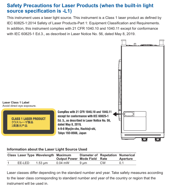
Laser safety (including L1 built-in light source model):
The equipment is an IEC 60825-1:2014 Class 1 laser product with a built-in reference light source (wavelength 1.53 μ m, output power 0.04mW). Infrared light is continuously emitted from the optical output connector, and direct viewing is strictly prohibited as it may cause visual impairment;
Avoid direct laser irradiation on the human body, especially the eyes, during measurement.
Environmental safety:
Prohibited from use in flammable and explosive environments, rainy or humid places;
The equipment is a Class A device used in industrial environments and may cause radio interference when used in residential areas. Users need to solve the interference problem themselves.
(2) Installation conditions
Physical environment:
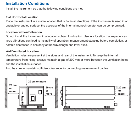
The installation position should be horizontally stable to avoid vibration (vibration may cause a decrease in monochromator accuracy and measurement interruption);
There are ventilation holes on the side and back of the equipment, and the distance between the ventilation holes and surrounding objects should be kept at least 200mm to prevent internal overheating;
Environmental temperature: 5-35 ℃, humidity: 20% -80% RH (non condensing), avoid direct sunlight, near heat sources, and dust/corrosive gas environments.
Rack installation (requires separate purchase of rack kit):
|Kit Name | Model | Specification|
|EIA Single Installation Rack Kit | 751533-E4 | Suitable for EIA Standard Rack|
|JIS Single Installation Rack Kit | 751533-J4 | Suitable for JIS standard racks, etc|
During installation, it is necessary to remove the handles on both sides of the device and the bottom support feet to ensure that there is a reserved space of ≥ 10cm around the rack for heat dissipation, and the bottom support does not block the ventilation holes.
Equipment operation: from configuration to measurement
(1) Hardware connection and software configuration
Core hardware connection:
Optical interface connection: Optical input and calibration output need to be connected to optical fibers through corresponding connector adapters (such as AQ9447, AQ9441), and only FC/SC type optical connectors are supported;
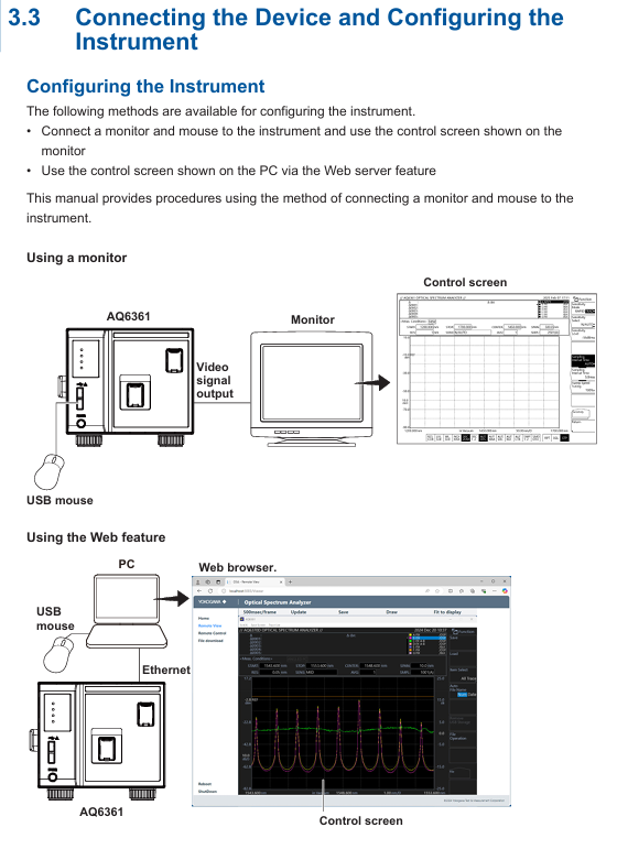
External device connection: PC connects devices through Ethernet/USB, monitor connects devices through Video OUT (XGA), mouse/keyboard connects through USB interface (supports USB HID Class 1.1 standard devices).
Software device registration and connection:
|Step | Operation Content|
|1 | Start AQ6361, enter the device connection window, click "Add" for the first connection, and select the communication method (Ethernet/USB)|
|2 | Click "Search" to search for devices, check the measuring instrument (such as AQ6361) and external devices, and click "Register" to complete the registration|
|3 | Check the target device in the registration list and click "Next" to enter the measurement and display settings window|
Key parameter configuration:
RAM data channel settings: Import symbol definition files (. a2l format) in the "Measurement Setting" window, or manually enter symbols, addresses, and data types to add RAM data channels;
Time reference synchronization: Check "Relative time" in "DAQ Setting", synchronize external devices based on the measuring instrument clock, and configure the data saving path (default: C: Users Username Documents YOKOGAWA IS8000).
(2) Startup and calibration process
Startup steps:
|Step | Operation Content|
|1. Connect the power cord, turn on the "MAIN POWER" switch on the back, and the front POWER light will turn orange|
|After waiting for a few seconds, press the "POWER" switch on the front, the light turns green, the device starts and initializes (displaying STEP 1/9 to STEP 9/9)|
|After initialization, enter the measurement interface and preheat for 1 hour before performing wavelength calibration|
Wavelength calibration (key step to ensure measurement accuracy):
Built in light source calibration (- L1 model): Connect the optical input and calibration output with 9.5/125 μ m single-mode fiber, enter "SYSTEM>Wavelength Calibration>Built in Source", click "Execute", and the calibration takes about a few minutes;
External light source calibration: Supports laser type (such as DFB-LD) or gas chamber absorption line type external light sources. After connection, set the wavelength in "External Laser/External Gas Cell" and perform calibration;
Attention: If the wavelength error exceeds ± 5nm, it is necessary to contact the Yokogawa dealer for re adjustment, as it cannot be calibrated through the built-in light source.
Resolution calibration: Use a stable single-mode laser source (output power ≥ -20dBm, linewidth ≤ 5MHz), connect it, enter "SYSTEM>Res BW Calibration", click "Execute" to complete the calibration, and the device will automatically correct the equivalent noise bandwidth after calibration.
(3) Measurement Execution and Data Management
Measurement condition setting:
Select the device in the "Device Control" panel, configure parameters such as sampling rate, trigger mode, sensitivity, and ensure that the measurement cycle of external devices (such as optical amplifiers) matches the pulse frequency of the device;
Supports three modes: "Single Sweep", "Repeat Sweep", and "Auto Sweep". Auto mode can automatically optimize measurement conditions.
Measurement operation:
|Operation | Function Description|
|Monitor Start | Start measurement (only monitors, does not record data)|
|Record Start | Start Record (Synchronize measurement and recording when monitoring is not started)|
|Record Stop | Stop recording (measurement continues)|
|Monitor Stop | Stop measurement (when recording has not stopped, synchronously stop measurement and recording)|
Data saving and loading:
The data is automatically saved in. mf4 format (including waveform and RAM data), and the default path can be modified in "DAQ Setting";
When loading data, the software opens the. mf4 file or loads the. wdf (waveform) and. mdf (RAM data) files offline, and the software automatically aligns the timeline.
Maintenance and troubleshooting
(1) Daily maintenance
Cleaning requirements:
Equipment casing: Wipe with a clean dry cloth after power failure, and prohibit the use of volatile chemicals (to prevent fading and deformation);
Optical interface: Clean the end face of the optical connector with a cotton swab dipped in pure alcohol to ensure that there is no dust (dust may affect optical performance and even damage the monochromator).
Regular inspection:
|Check project | cycle | operation content|
|Wavelength accuracy check | Regular | Use a light source with known wavelength accuracy (such as a gas laser) to measure the spectrum and confirm that the center wavelength error of THRESH 3dB is within the specified range|
|Level accuracy inspection | Regular | Using a 1310nm/1550nm light source, compare the peak level measured by the equipment with the reading of the optical power meter, and ensure that the error meets the specifications|
|Firmware Update | On Demand | Download the latest firmware from Yokogawa's official website and update via USB or Ethernet (power off is prohibited during update to avoid device failure to start)|
(2) Fault handling and warning information
Common faults and countermeasures:
|Fault phenomenon | Possible causes | Response measures|
|No response upon startup | Power cord not connected properly, power voltage mismatch | Check power cord connection, confirm voltage is within the range of 90-264VAC|
|Abnormal measurement data | Optical interface contamination, wavelength calibration not performed | Clean optical interface, wavelength calibration performed|
|Communication failure | Loose USB/Ethernet connection, incorrect IP address | Reconnect the cable and check the IP address (default 192.168.1.100)|
Warning message interpretation: Chapter 5.7 of the manual provides a detailed list of 380+warning messages, with the core categories as follows:
|Warning type | Scope | Example and reason|
|Warning after function execution | 1-49 | 'Unsuitable resolution' (resolution setting does not match span/sample size, which may result in incomplete data extraction)|
|Function unable to execute warning | 50-199 | "USB storage not found" (USB storage device not inserted)|
|Hardware malfunction warning | 200-299 | "Fan motor stopped" (the fan stops running and automatically shuts down after 10 seconds, please contact maintenance)|
Core technical parameters
The key specifications of AQ6361 vary depending on the model (Standard Type -10/High Performance Type -20) and wavelength range (- SW/- EW), with the following core parameters:
Parameter Category Standard Type (-10) High Performance Type (-20)
Wavelength range SW: 1200-1700nm; -EW: 700-1700nm same standard type
Wavelength accuracy - SW: ± 0.02nm (1520-1580nm), ± 0.04nm (1580-1620nm) - SW: ± 0.02nm (1450-1620nm)
Wavelength resolution of 0.05, 0.1, 0.2, 0.5, 1, 2nm 0.03, 0.05, 0.1, 0.2, 0.5, 1, 2nm
Level sensitivity TRAD mode: -80dBm (1300-1620nm, HIGH2); RAPID mode: -73dBm (1300-1620nm, RAPID6) same standard type
Maximum input power+20dBm (single channel),+25dBm (total input power) same as standard type
Scanning time TRAD mode (NORM-AUTO): 0.2s (span ≤ 100nm, sample size 1001) Same as standard type
Suitable for single-mode (SM: 9.5/125 μ m) and multi-mode (GI: 50/62.5 μ m) equivalent standard types of optical fibers
- YOKOGAWA
- Reliance
- ADVANCED
- SEW
- ProSoft
- WATLOW
- Kongsberg
- FANUC
- VSD
- DCS
- PLC
- man-machine
- Covid-19
- Energy and Gender
- Energy Access
- Renewable Integration
- Energy Subsidies
- Energy and Water
- Net zero emission
- Energy Security
- Critical Minerals
- A-B
- petroleum
- Mine scale
- Sewage treatment
- cement
- architecture
- Industrial information
- New energy
- Automobile market
- electricity
- Construction site
- HIMA
- ABB
- Rockwell
- Schneider Modicon
- Siemens
- xYCOM
- Yaskawa
- Woodward
- BOSCH Rexroth
- MOOG
- General Electric
- American NI
- Rolls-Royce
- CTI
- Honeywell
- EMERSON
- MAN
- GE
- TRICONEX
- Control Wave
- ALSTOM
- AMAT
- STUDER
- KONGSBERG
- MOTOROLA
- DANAHER MOTION
- Bentley
- Galil
- EATON
- MOLEX
- Triconex
- DEIF
- B&W
- ZYGO
- Aerotech
- DANFOSS
- KOLLMORGEN
- Beijer
- Endress+Hauser
- schneider
- Foxboro
- KB
- REXROTH
- YAMAHA
- Johnson
- Westinghouse
- WAGO
- TOSHIBA
- TEKTRONIX
- BENDER
- BMCM
- SMC
- HITACHI
- HIRSCHMANN
- XP POWER
- Baldor
- Meggitt
- SHINKAWA
- Other Brands
- UniOP
- KUKA
- IBA
- Beckhoff
-
LTI SC52.0040.0012.0000.0 - Servo Drive
-
Lti SC52.0040.0012.0000.0 - Servo Drive
-
Milton Industries LTI Tool By Milton LT1240 - 1/2" Drive Lugnut Remover
-
LTi Drives SO84.200.P030.0000.0-W - Servo Spindle Drive
-
LTI DRIVES LSP08-035-320-30-B0R1PY170 - Servo Motor
-
LTI DRIVES SE84.200.SC00.0001.0-W - Servo Drive
-
Lust CDE34.005.W2.2 - Lti Drives Controller
-
LTi SO84.012.0030.0011.2 - ServoOne Servo Drive
-
LTi Drives SO CM-P.0010.11.00.0 - Servo Drive Controller
-
LTi CDE34.017.W3.0 - Servo Drive
-
LTI Drives CDB32.004, C2.0,SH - Positioning Controller
-
LUST CM-CAN1 - LTi DRIVES Communication Module
-
LTi SO84.012.1030.0000.2 - Servo Drive
-
LTI MOOG CDE54.044 - PITCHMASTER FREQUENCY CONVERTER 181-01019
-
MOOG LTI 181-01019 CDE54.044 - PITCHMASTER FREQUENCY CONVERTER
-
Lust LTi Drives CDE34.010,D2.0 - Servo Drive Controller
-
LTI SO84.032.0003.0101.2 - Servo Drive
-
Seagate 9CC132-302 Harris LTI-CS IRT-34-0021-01 - Hard Drive 160GB
-
LTI SO84.032.0003.0001.2 - Servo Drive
-
LTI SO24.007.0070.0000.1 - SERVO CONTROLLER
-
LTi drive CDA32.003.C3.0.H05-01.PC1 - Servo Drive
-
LTI SO84.016.0030.0000.2 - SERVO CONTROLLER
-
LUST LTI CD A34.008,W1.4, BR - SERVO DRIVE
-
MOOG LTI 181-01019 CDE54.044 - PITCHMASTER FREQUENCY CONVERTER
-
LTI MOOG 181-01019 - PITCH Master Servo Drive CDE54.044
-
LTI SERVO ONE SO84.045.0030.0001.2-W - Drive
-
LUST LTi SO84.032.0040.0000.2 - SERVO ONE DRIVE
-
LTi Drives LSH-074-2-30-3 20/T1,G6.1M - SERVO MOTOR
-
LTI SO84.016.0000.0101.2 - servo drive
-
LTI SA54.0550.0033.0000.0 - Servo Drive
-
LTI SA54.0550.0033.0000.0 - Servo Drive
-
LTI LT 4850 - 3/8" Drive 3-Pc Twist Socket Transmission Drain Plug Removal System
-
LTI Tools LT4400-30 Lock Technology - 3/4" Twist Socket 1/2" Drive Lugnut Remover
-
LTI Tools LT-1400C - 1/2 Drive Wheel Torque Extension Tool
-
LTI Tools LT1250 - 1/2" Drive Dual Sided Socket Lug Nut Remover Tool
-
LTI SO84.032.0003.0101.2 - Servo Drive
-
LTI MOOG 181-01019 - PITCH Master Servo Drive CDE54.044
-
MOOG LTI 181-01019 CDE54.044 - PITCHMASTER FREQUENCY CONVERTER
-
MOOG LTI 181-01019 CDE54.044 - PITCHMASTER FREQUENCY CONVERTER
-
MOOG LTI 181-01019 CDE54.044 - PITCHMASTER FREQUENCY CONVERTER
-
LTI SA54.0550.0033.0000.0 - Servo Drive
-
LTI Tools LT-4800 - 7 Piece Twist Socket 3/8" Drive Oil Drain Plug Removal Set
-
LTI SA54.0550.0033.0000.0 - Servo Drive
-
LTI Drive SO24.007.00300000.0 - Servo Drive
-
LTI TOOLS LTI 1400-I - Drive Wheel Torque Extension
-
LTI Tools LT4400-3 - 3/4" 19mm Twist Socket 1/2" Drive Lugnut
-
LTI TOOLS LTI 1400-BB - Drive Wheel Torque Extension
-
LTI SO84.032.0003.0101.2 - Servo Drive
-
LTI Tools LT-4512 - 3/8" Drive 12mm Twist Socket
-
LTI MOTION Luster SO84.032.0003.0001.2 - Servo Drive
-
LTI Tool By Milton LT1600P - 1" Drive Torx Stick
-
LTI Lust VF1424L,HF,OP2,S56 - Variable Frequency Drive
-
LUST CDA32.004,C1.4,H08,B0 - SERVO DFRIVE CM-CAN1 Module
-
LTI SO84.045.0002.0001.2-W - Drive
-
LTI Lust VF1404M,C9,PT1,BR1 - Inverter Type VF1404M
-
LTI SA54.0550.0033.0000.0 - Servo Drive
-
LTI Tools LT-1400C - 1/2" Drive Wheel Torque Extension
-
Lust LTI DRiVES CDA32.006, C3.0, H09 - Variateur De Fr茅quence Frequency Inverter
-
LTI MOOG CDE54.044 - PITCH master SERVO DRIVE
-
LTI MOOG CDE54.044 - PITCH master SERVO DRIVE
-
LTI SO84.143.0020.0101.2-W - servo drive
-
LTI MOTION SC34.0200.0011.0000.0 - Servo drives
-
LTI SO84.032.0003.0001.2 - Servo Drive
-
LTI DRIVES GmbH MS100 - Assembly Set Mounting Kit
-
LTI SO84.032.0003.0001.2 - Servo Drive
-
LTI SO84.032.0003.0001.2 - Servo Drive
-
LTI MOTION SO84.032.0003.0101.2 - servo drive
-
LTI SO84.032.0003.0101.2 - Servo Drive
-
LTI MOOG CDE54.044 - PITCH master SERVO DRIVE
-
LTI MOTION CDE32.004.C2.4 - Servo drives
-
LTI CDD34.032锛學x.x锛孊R锛孭C1 - Servo Drive
-
Lust LTI DRiVES CDA32.006, C3.0, H09 - Inversor De Frecuencia Frequency Inverter
-
Lust SO84.008.0030.1000.0 - Servo One LTi Drive
-
LTI MOTION SO84.032.0003.0101.2 - Servo drives
-
LUST LTi CDA32.004,C1.4 - SERVO DRIVE
-
LTI MOOG CDE54.044 - PITCH Master SERVO DRIVE
-
LTI KEBA CDB32.004 C2.7, SH - PN: 08673530 Frequency Inverter
-
LTI Tools LT-1400C - 1/2" Drive Wheel Torque Extension
-
LTI LT1400-E - 1/2" Drive Wheel Torque Extension
-
LTI MOOG 181-01019 - PITCH master SERVO DRIVE CDE54.044
-
LTI LSN-097-0510-30-560/T1 - Actuator Motor
-
LTI Tools LT 4800 - 7 Piece 3/8" Drive Twist Socket Oil Drain Plug Removal System
-
LTI DRIVES GmbH MS100 - MONTAGESET Assembly Set Mounting Kit
-
Lti SC52.0040.0012.0000.0 - Servo Drive
-
LTI DRIVES GmbH MS100 - Juego De Montaje Assembly Set Mounting Kit
-
LTi DSM4-14.2-21R83-200 - Drives servomoteur Servo Motor
-
MOOG CDE 54.044.GDA - Pitch Master Industrielle Turbine Lti Drive
-
LTI SO24.004.0030.1000.0 - Servo Drive Controller
-
Lti MOOG CDE54.044 - Pitch Master Servo Drive
-
Lust LTI DRiVES CDA32.006, C3.0, H09 - Inverter
-
LTI MOTION GMBH CDB34.006,W3.0,PC1,H39 - Frequency inverter
-
LTI SO84.032.0003.0001.2 - Servo Drive
-
MOOG CDE 54.044.D - Pitch Master Industrielle Turbine Lti Drive
-
LTI TOOLS LT-1460 - 1/2" DRIVE WHEEL TORQUE EXTENSION KIT 5 PIECE SET
-
Lust Cdb32.003, C2.4 - Lti Drives Servoregulador Frecuencia Servo Controller Inverter
-
Lust LTI DRIVES CDA32.006, C3.0, H09 - Frequency Inverter
-
Lust Lti SO82.004.0030.0000.2 - Servo Drive
-
LTI MOTION SC34.0200.0011.0000.0-SL - Servo drives
-
LTI MOTION SA54.0075.0033.0000.0 - Servo drives
-
LTI MOTION SC32.0075.1011.0000.0 - Servo drives
-
LTI Servo-One Junior SO22.006.0080.1000.0 - Servo Controller Servoregler
-
LUST CDA32.004, C1.4, H08, B0 - Servo Drive & LTI CM-CAN1 Module
-
LTI DRIVES LSP08-035-320-30-B0R1PY170 - Servo Motor
-
LUST LTI CDA32.004,C1.4.H08.B0 - SERVO CONTROLLER DRIVES
-
LUST LTi DRiVES CDS44.072LC1.2 - Servo Drive
-
Lti Servo-One Junior SO22.006.0082.1000.0 - Servo Controller Servoregler
-
LUST CDA32.008,C2.0,HF - Lti DRIVES Spindle Drive Inverter
-
LTI SO22.003.0082.0000.0 - Servo Drives One junior Servo Controller Servoregler
-
Lust Lti Drives CM-CAN1 - Communication Module
-
LUST Lti Drives Vf1202s, G8, I6 - Frequency Inverter Drive
-
LTI DRIVES BR-090.03.540.UR.H38 - Bremswiderstand Brake Resistor
-
LTi DRIVES PM-E40.2DRA054P - Wind Turbine Pitch Control Inverter
-
LTi Drives GmbH br-110.01.540-UR - Brake Resistor
-
LTI Drives LSN-097-0960-30-0560/T1,S4,B - Servo Motor
-
LUST CDA34.006.C2.0 - LTI Drives Servoregler
-
LUST LTI DRIVES SERVO ONE JUNIOR SO24.002.0020.0000.1 - Servo Drive Controller
-
LTI MOTION SO84.032.0003.0001.2 - Servo drives
-
LTI DDTD750V2-120 - IBOP ACTUATOR CYLINDER FOR TOP DRIVE
-
LTI CDE32.004, C2.4 - SERVO DRIVE
-
LUST LTI DRIVES CDD34.017 W3.4PC1 - Servo Drive Controller
-
LTI CDA3208,C3,0,HF - AC SERVO DRIVE
-
LUST LTI DRIVES LSH-074-3-30-560/T1,G6.1S - SERVO MOTOR
-
LUST Lti CDB32.004.C2.4.SH - AC Servo Drive
-
LTi CDA32.006, C3.0, H09 - Servo Drive
-
LTI SO22.003.0010.0000.0 - Servo Drive Servo one junior Servoregler Controller
-
LTi Drives DSM4-14.2-21R83-200 - Servo Motor
-
LUST Lti Drives Lsh-097-1-30-560/T1, 1R - Servomotor
-
LTI 1237 - 7 Piece 1/2" Drive Flip Socket Set

K-JIANG

Add: Jimei North Road, Jimei District, Xiamen, Fujian, China
Tell:+86-15305925923