
K-WANG


Yokogawa IS8000 Integrated Software ECU Monitoring and Synchronization Function
Yokogawa IS8000 Integrated Software ECU Monitoring and Synchronization Function
Functional positioning
The ECU monitoring synchronization option (/EM1 or - EM1) is an extended function of the IS8000 integrated software, which can synchronize the waveform measured by waveform measuring instruments (such as DL950, SL2000) with the RAM data obtained by the ECU monitor (such as RAMScope) based on the sampling clock for display, supporting joint data analysis.
Core functions and system configuration
(1) Functional principles and core characteristics
Synchronization principle: The sampling clock generated by the waveform measuring instrument is used as a synchronization signal to be transmitted to the ECU monitor, and the measurement data of both parties is loaded through IS8000 software to achieve synchronous display of waveform and RAM data on the PC side.
Core functions:
|Functional Category | Specific Description|
|Synchronized display | ECU monitor RAM data and waveform measurement instrument waveform data are aligned and displayed based on sampling clock|
|Measurement Control | Supports measurement start/stop and recording of start/stop operations for ECU monitors and measuring instruments|
|Data Storage | Automatically merge RAM data with waveform data and save them as. mf4 format files; Support saving symbol definitions as XML files|
|Offline synchronization | Supports offline loading of saved waveform data (. wdf format) and RAM data (. mdf format), achieving timeline synchronization by aligning the "FirstData" points|
(2) System configuration requirements
Hardware compatibility:
ECU monitor: Supports RAMScope GT122, GT170EXG (RAM measurement module only), the latest compatible models need to refer to Yokogawa official website;
Waveform measuring instruments: Yokogawa DL950, SL2000 (require installation of input modules that match the measurement target);
PC communication interface: It needs to support USB (USBTMC, VISA protocol) or Ethernet (VXI-11, HiSLIP protocol), and a dedicated USB driver needs to be installed (which can be downloaded from) https://tmi.yokogawa.com/library/ Download).
PC system requirements: According to the usage scenario, it can be divided into two types of configurations, as follows:
|Usage scenario | CPU requirements | Memory requirements | SSD requirements | Operating system|
|10G Ethernet communication/trigger DAQ (up to 24 hours continuous recording) | Intel Core i7-10700K and above (4 cores, 8 threads, 4.7 GHz+) | 16 GB and above | 512 GB and above (NVMe SSD recommended, read/write speed 3 GB/s+) | Windows 10 64 bit Windows 11|
|1G Ethernet/USB communication/offline analysis | Intel Core i5-10210U and above (4 cores, 8 threads, 4.2 GHz+) | 8 GB and above | 256 GB and above (read/write speed of 400 MB/s+) | Windows 10 64 bit Windows 11|
Additional requirements: Screen resolution of 1366 × 768 or higher (100% zoom), mouse and printer (optional) are required.
Operation process: from configuration to data management
(1) Hardware connection and software configuration
Hardware connection steps:
Connect the measuring instrument to the ECU monitor: Connect the sampling clock output terminal (CLKO, with GND) of DL950/SL2000 to the synchronization signal input terminal of the ECU monitor;
Connect PC: The measuring instrument is connected to the PC via Ethernet or USB, and the ECU monitor is connected to the PC via USB;
Special note: If the ECU monitor is RAMScope, it is necessary to first configure RAM measurement related settings through RAMScope V/VP and verify the data acquisition function. Close the software before connecting to IS8000.
Software device registration and connection:
|Step | Operation Content|
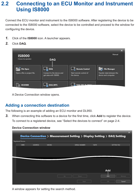
|1 | Start the IS8000 software, click on "DAQ" to enter the device connection window|
|When connecting for the first time, click "Add", select the communication method (Ethernet/USB), and then click "Search" to search for the device|
|3 | Check the measurement instrument (such as DL950) and ECU monitor (such as RAMScope) in the search results, and click "Register" to complete the registration|
|4. Check the target device in the registered device list and click "Next" to enter the measurement and display settings window|
RAM data measurement channel settings:
Click "Add Channel" in the "Measurement Setting" window and import the symbol definition file (in. a2l format, generated by RAMScope VP) through "Edit>Import File", or manually enter the symbol, address, and data type;
After importing, click "Add" to add the RAM data channel to the channel list. After confirmation, click "Next" to enter DAQ settings.
Time reference synchronization setting:
Check 'Relative time' in the 'Time Base' section of the 'DAQ Setting' window (based on measuring instrument clock synchronization ECU monitor);
Configure the record saving path (default path: C: Users Username Documents YOKOGAWA IS8000), file name rules, etc. Click "OK" to complete the configuration and enter the DAQ control interface.
(2) Measurement Execution and Data Management
Measurement condition setting:
In the "Device Control" panel of the DAQ control interface, select the measuring instrument and ECU monitor respectively, and configure parameters (such as DL950 sampling rate, trigger mode, and RAMScope measurement cycle);
Key synchronization requirements: The measurement cycle of the ECU monitor should match the pulse frequency of the measuring instrument (such as DL950 pulse rate of 1 kHz corresponding to RAMScope cycle of 1 ms), and the "External Clock" should be turned on to synchronize the external clock.
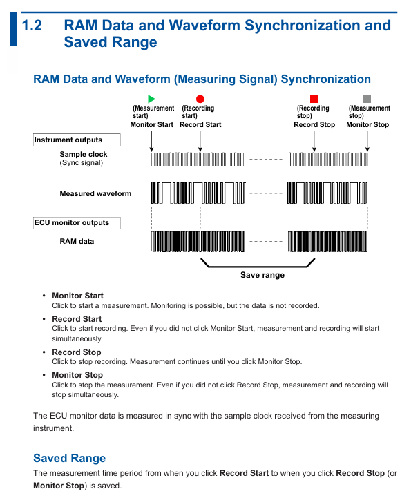
Measurement and recording operations:
|Operation steps | Function description|
|1 | Click on "Monitor Start": Start measurement (only monitoring, no data recording)|
|2 | Click on "Record Start": Start recording (if monitoring is not started, measurement and recording will be synchronized)|
|3 | Click "Record Stop": Stop recording (measurement continues, monitoring can continue)|
|4 | Click "Monitor Stop": Stop the measurement (if the recording is not stopped, the measurement and recording will be stopped synchronously)|
Caution: Do not operate the measuring instrument panel during the recording period; PC needs to disable standby/sleep mode to avoid software interruption; When there is a connection error, the measuring instrument needs to be restarted.
Data saving and loading:
Data saving: After stopping recording/measurement, the data is automatically saved as a. mf4 format file. If "Automatically open the last saved file" is checked, the file will be automatically opened after saving;
Data loading: Refer to the IS8000 user manual (IM IS8000-01EN), open the saved. mf4 file (or. wdf and. mdf files in offline scenarios) in the software, and the software will automatically align the timeline to display the data.
(3) Offline synchronization operation (Appendix supplement)
For scenarios without real-time connectivity requirements, the offline synchronization process is as follows:
Connect the measuring instrument and ECU monitor according to the hardware connection requirements, and disconnect from the PC;
Configure measuring instruments separately (set external sampling clock, pulse rate, trigger mode) and ECU monitors (synchronize external clock, monitoring time needs to be longer than measuring instruments);
Start the ECU monitor (enter clock standby) → Press the "START" button on the measuring instrument (output sampling clock, ECU starts to acquire RAM data) → Press the "STOP" button on the measuring instrument (stop clock and RAM data acquisition) → Stop the ECU monitor;
Save the measurement instrument data (in. wdf format) and ECU data (in. mdf format) separately, load the two files in IS8000, and synchronize the software display by aligning the "FirstData" points.
Usage restrictions and precautions
License restriction: A single license supports the use of this option on two PCs simultaneously; It is prohibited to connect multiple PCs to the same measuring instrument at the same time.
Communication limitation: When controlling measuring instruments, only one communication interface (Ethernet/USB) is supported at a time; Prohibit the simultaneous use of multiple interfaces.
Operation taboos: It is prohibited to operate the measuring instrument panel during data recording; The PC needs to disable standby/sleep mode, otherwise it may cause software interruption.
Fault handling: If there is a connection error, prioritize restarting the measuring instrument; If synchronization is abnormal, check the matching between the sampling clock connection and parameters (such as pulse rate and measurement period).
- YOKOGAWA
- Reliance
- ADVANCED
- SEW
- ProSoft
- WATLOW
- Kongsberg
- FANUC
- VSD
- DCS
- PLC
- man-machine
- Covid-19
- Energy and Gender
- Energy Access
- Renewable Integration
- Energy Subsidies
- Energy and Water
- Net zero emission
- Energy Security
- Critical Minerals
- A-B
- petroleum
- Mine scale
- Sewage treatment
- cement
- architecture
- Industrial information
- New energy
- Automobile market
- electricity
- Construction site
- HIMA
- ABB
- Rockwell
- Schneider Modicon
- Siemens
- xYCOM
- Yaskawa
- Woodward
- BOSCH Rexroth
- MOOG
- General Electric
- American NI
- Rolls-Royce
- CTI
- Honeywell
- EMERSON
- MAN
- GE
- TRICONEX
- Control Wave
- ALSTOM
- AMAT
- STUDER
- KONGSBERG
- MOTOROLA
- DANAHER MOTION
- Bentley
- Galil
- EATON
- MOLEX
- Triconex
- DEIF
- B&W
- ZYGO
- Aerotech
- DANFOSS
- KOLLMORGEN
- Beijer
- Endress+Hauser
- schneider
- Foxboro
- KB
- REXROTH
- YAMAHA
- Johnson
- Westinghouse
- WAGO
- TOSHIBA
- TEKTRONIX
- BENDER
- BMCM
- SMC
- HITACHI
- HIRSCHMANN
- XP POWER
- Baldor
- Meggitt
- SHINKAWA
- Other Brands
- UniOP
- KUKA
- IBA
- Beckhoff
-
LTI SC52.0040.0012.0000.0 - Servo Drive
-
Lti SC52.0040.0012.0000.0 - Servo Drive
-
Milton Industries LTI Tool By Milton LT1240 - 1/2" Drive Lugnut Remover
-
LTi Drives SO84.200.P030.0000.0-W - Servo Spindle Drive
-
LTI DRIVES LSP08-035-320-30-B0R1PY170 - Servo Motor
-
LTI DRIVES SE84.200.SC00.0001.0-W - Servo Drive
-
Lust CDE34.005.W2.2 - Lti Drives Controller
-
LTi SO84.012.0030.0011.2 - ServoOne Servo Drive
-
LTi Drives SO CM-P.0010.11.00.0 - Servo Drive Controller
-
LTi CDE34.017.W3.0 - Servo Drive
-
LTI Drives CDB32.004, C2.0,SH - Positioning Controller
-
LUST CM-CAN1 - LTi DRIVES Communication Module
-
LTi SO84.012.1030.0000.2 - Servo Drive
-
LTI MOOG CDE54.044 - PITCHMASTER FREQUENCY CONVERTER 181-01019
-
MOOG LTI 181-01019 CDE54.044 - PITCHMASTER FREQUENCY CONVERTER
-
Lust LTi Drives CDE34.010,D2.0 - Servo Drive Controller
-
LTI SO84.032.0003.0101.2 - Servo Drive
-
Seagate 9CC132-302 Harris LTI-CS IRT-34-0021-01 - Hard Drive 160GB
-
LTI SO84.032.0003.0001.2 - Servo Drive
-
LTI SO24.007.0070.0000.1 - SERVO CONTROLLER
-
LTi drive CDA32.003.C3.0.H05-01.PC1 - Servo Drive
-
LTI SO84.016.0030.0000.2 - SERVO CONTROLLER
-
LUST LTI CD A34.008,W1.4, BR - SERVO DRIVE
-
MOOG LTI 181-01019 CDE54.044 - PITCHMASTER FREQUENCY CONVERTER
-
LTI MOOG 181-01019 - PITCH Master Servo Drive CDE54.044
-
LTI SERVO ONE SO84.045.0030.0001.2-W - Drive
-
LUST LTi SO84.032.0040.0000.2 - SERVO ONE DRIVE
-
LTi Drives LSH-074-2-30-3 20/T1,G6.1M - SERVO MOTOR
-
LTI SO84.016.0000.0101.2 - servo drive
-
LTI SA54.0550.0033.0000.0 - Servo Drive
-
LTI SA54.0550.0033.0000.0 - Servo Drive
-
LTI LT 4850 - 3/8" Drive 3-Pc Twist Socket Transmission Drain Plug Removal System
-
LTI Tools LT4400-30 Lock Technology - 3/4" Twist Socket 1/2" Drive Lugnut Remover
-
LTI Tools LT-1400C - 1/2 Drive Wheel Torque Extension Tool
-
LTI Tools LT1250 - 1/2" Drive Dual Sided Socket Lug Nut Remover Tool
-
LTI SO84.032.0003.0101.2 - Servo Drive
-
LTI MOOG 181-01019 - PITCH Master Servo Drive CDE54.044
-
MOOG LTI 181-01019 CDE54.044 - PITCHMASTER FREQUENCY CONVERTER
-
MOOG LTI 181-01019 CDE54.044 - PITCHMASTER FREQUENCY CONVERTER
-
MOOG LTI 181-01019 CDE54.044 - PITCHMASTER FREQUENCY CONVERTER
-
LTI SA54.0550.0033.0000.0 - Servo Drive
-
LTI Tools LT-4800 - 7 Piece Twist Socket 3/8" Drive Oil Drain Plug Removal Set
-
LTI SA54.0550.0033.0000.0 - Servo Drive
-
LTI Drive SO24.007.00300000.0 - Servo Drive
-
LTI TOOLS LTI 1400-I - Drive Wheel Torque Extension
-
LTI Tools LT4400-3 - 3/4" 19mm Twist Socket 1/2" Drive Lugnut
-
LTI TOOLS LTI 1400-BB - Drive Wheel Torque Extension
-
LTI SO84.032.0003.0101.2 - Servo Drive
-
LTI Tools LT-4512 - 3/8" Drive 12mm Twist Socket
-
LTI MOTION Luster SO84.032.0003.0001.2 - Servo Drive
-
LTI Tool By Milton LT1600P - 1" Drive Torx Stick
-
LTI Lust VF1424L,HF,OP2,S56 - Variable Frequency Drive
-
LUST CDA32.004,C1.4,H08,B0 - SERVO DFRIVE CM-CAN1 Module
-
LTI SO84.045.0002.0001.2-W - Drive
-
LTI Lust VF1404M,C9,PT1,BR1 - Inverter Type VF1404M
-
LTI SA54.0550.0033.0000.0 - Servo Drive
-
LTI Tools LT-1400C - 1/2" Drive Wheel Torque Extension
-
Lust LTI DRiVES CDA32.006, C3.0, H09 - Variateur De Fr茅quence Frequency Inverter
-
LTI MOOG CDE54.044 - PITCH master SERVO DRIVE
-
LTI MOOG CDE54.044 - PITCH master SERVO DRIVE
-
LTI SO84.143.0020.0101.2-W - servo drive
-
LTI MOTION SC34.0200.0011.0000.0 - Servo drives
-
LTI SO84.032.0003.0001.2 - Servo Drive
-
LTI DRIVES GmbH MS100 - Assembly Set Mounting Kit
-
LTI SO84.032.0003.0001.2 - Servo Drive
-
LTI SO84.032.0003.0001.2 - Servo Drive
-
LTI MOTION SO84.032.0003.0101.2 - servo drive
-
LTI SO84.032.0003.0101.2 - Servo Drive
-
LTI MOOG CDE54.044 - PITCH master SERVO DRIVE
-
LTI MOTION CDE32.004.C2.4 - Servo drives
-
LTI CDD34.032锛學x.x锛孊R锛孭C1 - Servo Drive
-
Lust LTI DRiVES CDA32.006, C3.0, H09 - Inversor De Frecuencia Frequency Inverter
-
Lust SO84.008.0030.1000.0 - Servo One LTi Drive
-
LTI MOTION SO84.032.0003.0101.2 - Servo drives
-
LUST LTi CDA32.004,C1.4 - SERVO DRIVE
-
LTI MOOG CDE54.044 - PITCH Master SERVO DRIVE
-
LTI KEBA CDB32.004 C2.7, SH - PN: 08673530 Frequency Inverter
-
LTI Tools LT-1400C - 1/2" Drive Wheel Torque Extension
-
LTI LT1400-E - 1/2" Drive Wheel Torque Extension
-
LTI MOOG 181-01019 - PITCH master SERVO DRIVE CDE54.044
-
LTI LSN-097-0510-30-560/T1 - Actuator Motor
-
LTI Tools LT 4800 - 7 Piece 3/8" Drive Twist Socket Oil Drain Plug Removal System
-
LTI DRIVES GmbH MS100 - MONTAGESET Assembly Set Mounting Kit
-
Lti SC52.0040.0012.0000.0 - Servo Drive
-
LTI DRIVES GmbH MS100 - Juego De Montaje Assembly Set Mounting Kit
-
LTi DSM4-14.2-21R83-200 - Drives servomoteur Servo Motor
-
MOOG CDE 54.044.GDA - Pitch Master Industrielle Turbine Lti Drive
-
LTI SO24.004.0030.1000.0 - Servo Drive Controller
-
Lti MOOG CDE54.044 - Pitch Master Servo Drive
-
Lust LTI DRiVES CDA32.006, C3.0, H09 - Inverter
-
LTI MOTION GMBH CDB34.006,W3.0,PC1,H39 - Frequency inverter
-
LTI SO84.032.0003.0001.2 - Servo Drive
-
MOOG CDE 54.044.D - Pitch Master Industrielle Turbine Lti Drive
-
LTI TOOLS LT-1460 - 1/2" DRIVE WHEEL TORQUE EXTENSION KIT 5 PIECE SET
-
Lust Cdb32.003, C2.4 - Lti Drives Servoregulador Frecuencia Servo Controller Inverter
-
Lust LTI DRIVES CDA32.006, C3.0, H09 - Frequency Inverter
-
Lust Lti SO82.004.0030.0000.2 - Servo Drive
-
LTI MOTION SC34.0200.0011.0000.0-SL - Servo drives
-
LTI MOTION SA54.0075.0033.0000.0 - Servo drives
-
LTI MOTION SC32.0075.1011.0000.0 - Servo drives
-
LTI Servo-One Junior SO22.006.0080.1000.0 - Servo Controller Servoregler
-
LUST CDA32.004, C1.4, H08, B0 - Servo Drive & LTI CM-CAN1 Module
-
LTI DRIVES LSP08-035-320-30-B0R1PY170 - Servo Motor
-
LUST LTI CDA32.004,C1.4.H08.B0 - SERVO CONTROLLER DRIVES
-
LUST LTi DRiVES CDS44.072LC1.2 - Servo Drive
-
Lti Servo-One Junior SO22.006.0082.1000.0 - Servo Controller Servoregler
-
LUST CDA32.008,C2.0,HF - Lti DRIVES Spindle Drive Inverter
-
LTI SO22.003.0082.0000.0 - Servo Drives One junior Servo Controller Servoregler
-
Lust Lti Drives CM-CAN1 - Communication Module
-
LUST Lti Drives Vf1202s, G8, I6 - Frequency Inverter Drive
-
LTI DRIVES BR-090.03.540.UR.H38 - Bremswiderstand Brake Resistor
-
LTi DRIVES PM-E40.2DRA054P - Wind Turbine Pitch Control Inverter
-
LTi Drives GmbH br-110.01.540-UR - Brake Resistor
-
LTI Drives LSN-097-0960-30-0560/T1,S4,B - Servo Motor
-
LUST CDA34.006.C2.0 - LTI Drives Servoregler
-
LUST LTI DRIVES SERVO ONE JUNIOR SO24.002.0020.0000.1 - Servo Drive Controller
-
LTI MOTION SO84.032.0003.0001.2 - Servo drives
-
LTI DDTD750V2-120 - IBOP ACTUATOR CYLINDER FOR TOP DRIVE
-
LTI CDE32.004, C2.4 - SERVO DRIVE
-
LUST LTI DRIVES CDD34.017 W3.4PC1 - Servo Drive Controller
-
LTI CDA3208,C3,0,HF - AC SERVO DRIVE
-
LUST LTI DRIVES LSH-074-3-30-560/T1,G6.1S - SERVO MOTOR
-
LUST Lti CDB32.004.C2.4.SH - AC Servo Drive
-
LTi CDA32.006, C3.0, H09 - Servo Drive
-
LTI SO22.003.0010.0000.0 - Servo Drive Servo one junior Servoregler Controller
-
LTi Drives DSM4-14.2-21R83-200 - Servo Motor
-
LUST Lti Drives Lsh-097-1-30-560/T1, 1R - Servomotor
-
LTI 1237 - 7 Piece 1/2" Drive Flip Socket Set

K-JIANG

Add: Jimei North Road, Jimei District, Xiamen, Fujian, China
Tell:+86-15305925923