
K-WANG


GE AT868 AquaTrans ™ Ultrasonic water flowmeter
GE AT868 AquaTrans ™ Ultrasonic water flowmeter
Product Overview
Core functions
AT868 is an ultrasonic water flow meter (supporting 1 or 2 channels) that measures water flow velocity, volumetric flow rate, and mass flow rate based on the principle of time difference. It is suitable for flow monitoring of single-phase fluids such as clean water and sewage. It emits and receives signals through ultrasonic sensors, calculates fluid flow velocity, and converts it into flow data, supporting real-time display, data recording, and multiple output methods (analog, pulse/frequency).
Main features
Multi channel configuration: Standard 1 channel, optional 2 channels, improve accuracy by measuring average, difference, or sum through dual channels.
Flexible sensor types: Supports wet and clamp on sensors to meet different pipeline installation requirements.
Rich output and communication: equipped with 0/4-20mA analog output, pulse/frequency output (for total count), supports RS232/RS485 serial communication, compatible with PanaView ™ Software remote operation.
High adaptability: Suitable for pipe diameters ranging from 0.04 inches to 200 inches (1mm to 5m), with flow rates ranging from -40 to 40 feet per second (-12.2 to 12.2m/s), meeting the needs of industrial pipeline flow monitoring.
Installation and wiring
1. Installation points
Sensor location: It needs to be installed in a straight pipe section, with at least 10 times the upstream pipe diameter and at least 5 times the downstream pipe diameter without turbulence interference (such as valves, elbows); Prioritize installation on the side of the pipeline (to avoid gas accumulation at the top or slag accumulation at the bottom).
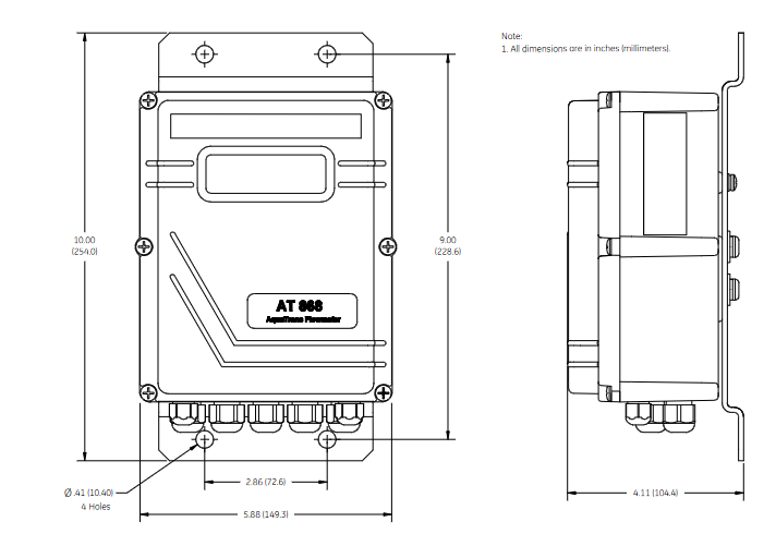
Electronic enclosure: Adopting NEMA 4X/IP66 protection level, suitable for indoor and outdoor installation, should be close to the sensor to shorten the cable length (supporting up to 1000 feet/300 meters).
Pipeline requirements: It is necessary to measure the outer diameter, wall thickness, material and other parameters of the pipeline and program them to ensure the accuracy of flow calculation.
2. Wiring specifications
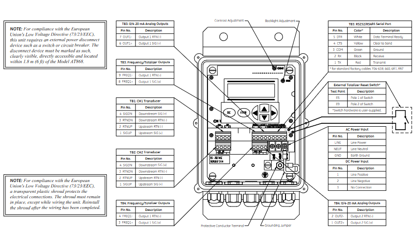
Power supply: Supports 85-265VAC or 12-28VDC, requires an external power-off device (such as a switch) that complies with the EU Low Voltage Directive, installed within a range of 6 feet.
Sensor wiring: Plug in or clip on sensors are connected through coaxial cables, and the cable length needs to be matched (with an error of ≤ 4 inches for frequencies ≤ 2MHz and ≤ 0.5 inches for frequencies>2MHz).
Output wiring:
Analog output (0/4-20mA): Load resistance ≤ 600 Ω, used for transmitting flow signals.
Pulse/frequency output: used for total count or frequency proportional to flow, maximum load 3A@100VDC .
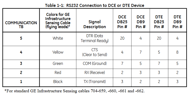
Communication wiring: RS232 is used to connect to PCs or printers, RS485 supports multi device networking, and must follow shielding grounding specifications to resist interference.
Programming and Settings
1. Basic parameter configuration
Channel activation: Activate the channel through the CHx ACTIV menu and select the sensor type (standard or special).
System parameters: Set the flow unit (such as gallon/minute, cubic meter/hour), total unit, and decimal places in CHx SYSTM, and optional mass flow rate (fluid density needs to be entered).
Pipeline and sensor parameters: Enter pipeline material, outer diameter, wall thickness, sensor frequency, path length (P), and axial length (L) in CHx PIPE. For clamp on sensors, lining parameters (material, thickness) also need to be set.
2. Advanced feature settings
Response time: Set the average measurement response time through the AVRG menu. It is recommended to select the "STATS" mode (fast response in steady state, fast tracking when flow changes).
Zero flow cutoff: Set a zero flow threshold (0-1 feet/second) in CHx I/O to avoid reading deviations caused by small fluctuations.
Tracking window: When the fluid sound velocity is unknown or fluctuates greatly, enable Tracing WINDOW to automatically track the sound velocity to ensure measurement accuracy.
Display function
1. Display screen and indicator lights
LCD display screen: A 2-line x 16 character LCD display screen that supports backlight adjustment and can display real-time measurement data, set parameters, and error codes.
Display content: It can be configured to display up to 4 parameters, including:
Flow rate (feet/second, meters/second)
Volume flow rate (such as gallons per minute, cubic meters per hour)
Accumulated total amount (such as total cubic feet, total cubic meters)
Diagnostic parameters (such as signal strength, sound speed, time difference, etc.)
Wheel display function: If multiple parameters are configured, the display screen will cycle at set intervals, with each parameter staying for a few seconds.
2. Display settings
Enter the settings menu:
Press [ESC]+[ENTER]+[ESC] to enter the user program.
Navigate to PROG → GLOBL → I/O → LCD, set the number of display parameters and specific parameters.
Parameter selection: Select the content to be displayed from the measured values (flow rate, flow rate) and diagnostic values (signal strength, sound velocity), supporting custom units (imperial/metric).
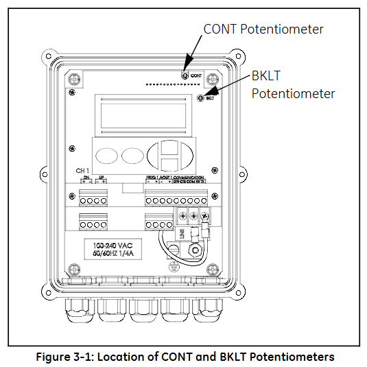
Contrast and brightness adjustment: Manually adjust through the potentiometer (CONT contrast, BKLT backlight) behind the panel to ensure clear visibility in different lighting environments.
Operation function
1. Totalizer Reset
Used to reset the accumulated traffic value to zero, supporting three methods:
Panel operation:
Enter the RESET menu and select YES to confirm the reset.
After resetting, the total amount of all channels will be reset to zero and accumulation will resume.
External switch reset:
Wiring should be done in advance (refer to the installation section) and configured as RESET in GLOBL-SYSTM → GATE OPTION.
Press and hold the external switch for 1 second, and the total amount will automatically reset to zero.
Software reset: via PanaView ™ The Clear Instrument Totalizers function of the software can be remotely operated.
2. Measurement pause and restart
Only supported through PanaView ™ Software operation:
Pause: Select Stop Measurement in Edit Functions → PAUSE MEASURMENT to pause the flow meter measurement and maintain the output signal at its final value.
Restart: Select Measure Flow to restore the measurement and update the output signal synchronously.
3. Diagnosis and Error Viewing
Diagnostic parameter display: Configure and display diagnostic parameters in GLOBL → I/O → LCD, including:
Upstream and downstream signal strength (SS up/SS dn, normal range 50-75)
Speed of Sound (SNDSP)
Time difference (DELTA T, normal ≤ 1 μ s)
Signal quality (Qup/Qdown, normal ≥ 1200)
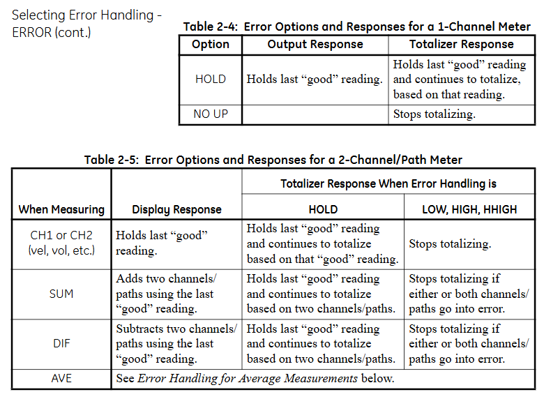
Error code: The display screen directly shows error codes (such as E1 indicating weak signal, E3 indicating flow rate exceeding limit). You can refer to Chapter 5 of the manual to investigate the cause (such as sensor alignment deviation, bubbles in the pipeline, etc.).
Key operation and menu navigation
1. Button functions
ESC: Exit the current menu or cancel the operation.
ENTER: Confirm the selection or enter the submenu.
↑/↓: Up and down navigation menu options or adjust parameter values.
←/→: Move the cursor (used to locate the digit when modifying parameters).
2. Common menu paths
View real-time data: default display interface, press ENTER to cycle through preset parameters.
Enter programming mode: ESC → ENTER → ESC → PROG, configurable channel parameters, units, outputs, etc.
Calibration output: ESC → ENTER → ESC → CALIB, used for calibrating 4-20mA analog output or pulse frequency output.
4、 Precautions
Display refresh rate: By default, it updates with the measurement cycle (response time can be set through the AVRG menu, ranging from 0.1-99 seconds).
Total overflow: When the cumulative value exceeds the maximum range, E9: Totalizer Overflow is displayed, and the total amount needs to be reset or the unit needs to be expanded (such as changing from "gallon" to "million gallon").
- YOKOGAWA
- Reliance
- ADVANCED
- SEW
- ProSoft
- WATLOW
- Kongsberg
- FANUC
- VSD
- DCS
- PLC
- man-machine
- Covid-19
- Energy and Gender
- Energy Access
- Renewable Integration
- Energy Subsidies
- Energy and Water
- Net zero emission
- Energy Security
- Critical Minerals
- A-B
- petroleum
- Mine scale
- Sewage treatment
- cement
- architecture
- Industrial information
- New energy
- Automobile market
- electricity
- Construction site
- HIMA
- ABB
- Rockwell
- Schneider Modicon
- Siemens
- xYCOM
- Yaskawa
- Woodward
- BOSCH Rexroth
- MOOG
- General Electric
- American NI
- Rolls-Royce
- CTI
- Honeywell
- EMERSON
- MAN
- GE
- TRICONEX
- Control Wave
- ALSTOM
- AMAT
- STUDER
- KONGSBERG
- MOTOROLA
- DANAHER MOTION
- Bentley
- Galil
- EATON
- MOLEX
- Triconex
- DEIF
- B&W
- ZYGO
- Aerotech
- DANFOSS
- KOLLMORGEN
- Beijer
- Endress+Hauser
- schneider
- Foxboro
- KB
- REXROTH
- YAMAHA
- Johnson
- Westinghouse
- WAGO
- TOSHIBA
- TEKTRONIX
- BENDER
- BMCM
- SMC
- HITACHI
- HIRSCHMANN
- XP POWER
- Baldor
- Meggitt
- SHINKAWA
- Other Brands
- UniOP
- KUKA
- IBA
- Beckhoff
-
Basler Electric DECS-250-CN1SN1N Automatic Voltage Regulator for Generator Excitation Control
-
ADLINK CPCI-6860A - 51-31310-OB10 industrial motherboard CompactPCI SBC
-
ADLINK AmITX-SL-G-H110 - 51-7A104-0A30 Mini-ITX Industrial Motherboard
-
ADLINK PXI-2005-003 - CPCI Industrial PC Data Acquisition Card Multi-Function DAQ
-
ADLINK DININ-814M - 51-14032-0A3D SCSI-100P cable connection Interface Terminal Board
-
ADLINK CPCI-3920NA/C2D15/M1G - 3U CompactPCI Intel Core 2 Duo Single Board Computer
-
ADLINK PCIE-8560 - 51-18014-0A20 Communication Card High Speed DAQ
-
ADLINK PCI-C154+ - Motion Control Card 4-axis Motion Controller Board
-
ADLINK PCI-RTV24 - image capture card Analog Video Frame Grabber
-
ADLINK NuPRO-842LV/P - 51-41360-0B30 Industrial Motherboard CPU Board
-
ADLINK cBP-3208/3208R - CPCI Board 3U 8-Slot CompactPCI Backplane
-
ADLINK PCI-8164 - 4-Axis Motion Controller PCI Card 51-12406-0A40
-
ADLINK PCIe-GIE64+ - 4-CH GigE Vision PoE+ Frame Grabber Video Capture Card
-
ADLINK CPCI-6860 / 6860A - CompactPCI Dual Xeon Single Board Computer
-
ADLINK IEC-915GV - REV 1.1 Industrial motherboard CPU Board
-
ADLINK ND-6520 - Technology RS-232 to RS-422RS-485 Converter NuDAM Module
-
ADLINK RTV-24 / PCI-MP4S - 51-12519-1C30 4-Channel Real Time Video Capture Board
-
ADLINK cPCI-6910 / cPCI-6910AM/M1G - cPCI-6910AM/DXL16/M1G/S80G(G)-3120 BOARD CompactPCI SBC
-
ADLINK NUPRO-A40H - Linghua 51-41807-1A30 Industrial Control Computer Motherboard
-
ADLINK USB-3488A - USB to GPIB INTERFACE USB-3488A(G) Controller Module
-
ADLINK PCI-8134A - motion control card 4-Axis Controller Card
-
ADLINK PCI-7432 - Board 32-Channel input / 32-output Isolated Digital I/O PCI Card
-
ADLINK PCI-8134A - 51-12421-0A10 motion controller card tested
-
ADLINK LPCIe-7230 - 32 CH Isolated Input/output Card 2 Interrupts Low Profile PCIe
-
ADLINK NuPRO-E340 - industrial computer motherboard 51-47807-0A30 PICMG 1.3 SHB
-
ADLINK PCI-7434 - High-speed Digital Acquisition Card 64-CH Isolated DO Card
-
ADLINK NuPRO-E330 - 51-41805-0A20 Indsutrial Board SHB Single Board Computer
-
ADLINK PCI-7248 - OPTO-22 48 CHANNEL DIO DIGITAL TTL/DTL I/O 51-12006-0A40 GP
-
ADLINK PCI-8134 - Motion control card 4-Axis Controller Card
-
ADLINK AMP-208C - Movimiento Control Tarjeta 51-12420-1A20 W/Expansión & Breakout
-
ADLINK PCI-8164 - 51-12406-0A40 PCB Board 4-Axis Motion Controller Card
-
ADLINK DIN-68Y-SGII / DIN-68M-J3A - Terminal Board Connector Interface Block
-
ADLINK PCIe-7432 - Technology 51-18402-0A10 PCIe Card With High Input Range
-
ADLINK PCI-8144 / PCI-8144N - Motion control card 4-Axis Stepper Controller Card
-
ADLINK HSL-HUB3/REPEATER - HIGH SPEED LINK EXTENSION MODULES Distributed Hub Module
-
ADLINK ND-6017 - Data Logging + Acquisition 8CH A/D input Mod NuDAM Module
-
ADLINK LPCIe-7250 - data acquisition card Low Profile 8-CH Relay Output Card
-
ADLINK PCI-7432 - I/O card 64-CH Isolated Digital Input Output PCI Card
-
ADLINK IMB-M43H - industrial control computer motherboard Q87 Chip Micro-ATX
-
ADLINK MP-C154 - Motion control Card 4-Axis Motion Controller Board
-
ADLINK PCI-RTV24 - image capture card Video Frame Grabber Card
-
ADLINK PCI-7250 - 8-CH Relay Output & 8-CH Isolated DI Card
-
ADLINK PCI-6308V - 8-CH 12-Bit Isolated Analog Output PCI Card PCB-I-E-1148=6EX2
-
ADLINK PCI-7248 - capture card 48-CH Opto-22 Compatible DIO Card
-
ADLINK HSL-AI16A02-M-VV - Analog Input Output Distributed Module
-
ADLINK NuPRO-A301 - Rev:1.4 NUPRO-A301 PICMG Full-Size Single Board Computer
-
ADLINK PCI-6208V-GL - 8-CH Voltage Analog Output PCI Card
-
ADLINK PCI-8134A - 51-12421-0A10 4-Axis Motion Controller Card
-
ADLINK MNET-S23 - TECHNOLOGY MNET S23 - SERVO DRIVER CONTROL MODULE
-
ADLINK M-342 - ATX I3 I5 I7 Q67 Industrial Motherboard
-
ADLINK NUPRO-780 - Industrial Motherboard CPU Board PICMG SBC
-
ADLINK MP-C154 / MP-C152 - 4-Axis Motion Control Card Pulse-Train Controller
-
ADLINK NuPRO-935A/LV10B0 - Motherboard 51-41802-0A10 GP w/RAM Industrial Control Board
-
ADLINK MP-C154 - Motion control card 4-Axis Motion Controller Mainboard
-
ADLINK PCI-7250 - PCI Acquisition Card 8-CH Relay Output Isolated DI Card
-
ADLINK ACL-7124 - Technology Inc.24 DIO Card Digital Input Output Card
-
ADLINK PCI-8554 A2 - Timer/Counter Data Acquisition Card
-
ADLINK DIN-825-GP4 - Terminal Block Interface Board Breakout Module
-
ADLINK NuPR0-761 - REV:1.1 Industrial motherboard Full-Size PICMG SBC
-
ADLINK MXE-1401/M8G (G) - Matrix Fanless Embedded Computer Industrial PC
-
ADLINK HSL-DI16DO16-UD-NN - Digital 16 Channel I/O Mod Distributed I/O Module
-
ADLINK ND6520 - NUDAM INTELLIGENT DA&C MODULE RS232-RS-422/RS485 CONVERTOR
-
ADLINK NUPRO-761 - REV:1.1 Industrial Motherboard CPU Board
-
ADLINK AMP-208C - Motion Control Card 51-12420-1A20 DSP-based 8-axis
-
ADLINK NuPRO-A301REV 1.4 - with packaging industrial computer motherboard PICMG SBC
-
ADLINK PCM-9112+ - 51-12300-0A2 industrial motherboard Multi-Function DAQ PC/104 Module
-
ADLINK PCM-7250+ - 8-CH Relay Outputs & 8-CH Isolated DI Module PC/104
-
ADLINK PCI-RTV24 - Image capture card Analog Video Frame Grabber
-
ADLINK PCI-8134 - Motion Controller PCI Card 4-Axis Controller Board
-
ADLINK PCI-7432 - Isolated Digital I/O PCI Card
-
ADLINK PCI-8554 A2 - acquisition card Timer/Counter Card
-
ADLINK PCI-8132 - Rev.A2 2-Axis Servo & Stepper Motion Controller Card
-
ADLINK PCI-8132 - Data Acquisition card 2-Axis Motion Controller Card
-
ADLINK EBP-13E4 - 51-46703-0A30 Industrial Backplane Board Passive Backplane
-
ADLINK PCI-800L - Electronic Card Interface Controller Card
-
ADLINK PCIe-GIE72 - 51-18531-0A10 PCB Board GigE Vision Frame Grabber
-
ADLINK DAQ-2010(G)-OOBO - Simultaneous-Sampling Multi-Function DAQ Card
-
ADLINK PCI-9112 - REV.B1 Multifunction DAQ Card Data Acquisition Card
-
ADLINK PCI-7230 - 51-12003-DA60 32-CH Isolated Digital I/O Card
-
ADLINK PCI-7432 - Data Acquisition Card Isolated Digital I/O PCI Card
-
ADLINK ETX-AT-N270-18/LXE - 51-71111-0A20 ETX CPU Module Motherboard
-
ADLINK HSL-DI32-UD-N - DIGITAL INPUT 32 POINTS MODULE Distributed I/O
-
ADLINK AMP-204C - Motion Control card DSP-Based 4-Axis Advanced Controller
-
ADLINK MNET-4XMOG-0050 - Four-axis Motion Controller Distributed Motion Module
-
ADLINK AMP-204C - Motion control card DSP-Based 4-Axis Pulse-Train Controller
-
ADLINK PCI-7442 - Switch card 64-Channel Datalogging & Acquisition Card
-
ADLINK M-302 - Industrial control motherboard ATX PC Board
-
ADLINK NUPRO-852 / NUPRO-852LV - Industrial motherboard Single Board Computer
-
ADLINK PCI-8134 - REV.B1. 4-Axis Motion Controller Card
-
ADLINK PCI-GIE62 + - 51-18502-0A20 2-CH GigE Vision Frame Grabber PoE Card
-
ADLINK PCI-MPG24 - 51-12523-0B20 MPEG4 Card Video Compression Hardware
-
ADLINK HSL-TB32-M-DIN - 32-CH I/O TERMINAL W/ HSL-AI16AO2-M-VV MODULE
-
ADLINK PCI-M114-GL - PCB Ver 2.1 Motion Controller Axis Card
-
ADLINK IMB-M40H - SYM76996H61 motherboard Industrial Computer Mainboard
-
ADLINK NUPRO-A40H - 51-41807-1A20 industrial control motherboard H61 Chip
-
ADLINK PCI-M114-GL - Axis Card Data Acquisition Card PCB VER2.2 Motion Controller
-
ADLINK PCI-8134 - Motion Controller PCI Card 4-Axis Controller Board
-
ADLINK PCI-8102 - Motion control card 2-Axis Servo & Stepper Controller
-
ADLINK NuPRO-841REV:3.0 - motherboard Industrial Control PC Board
-
ADLINK HSL-TB32-U-DIN REV A1 - Breakout Terminal Board Field I/O Module
-
ADLINK AMP-204C - Motion Control card DSP-Based 4-Axis Pulse-Train Controller
-
ADLINK NUPRO-A40H - 51-41807-1A20 industrial control motherboard H61 PC Board
-
ADLINK PCI-6308A / PCI-6308V - 51-12202-0A50 Isolated Analog Output Card
-
ADLINK AMP-204C - DSP-Based 4-Axis Advanced Pulse-Train Motion Controller
-
ADLINK PCI-7434 - Technology 64-Channel Isolated Digital I/O PCI Cards
-
ADLINK CPCI-6840 / CPCI-6840V / PM16/M1G-12G0 - CompactPCI Single Board Computer CPU Module
-
ADLINK PCIE-GIE74 - Motherboard Video Capture Card 51-18531-0A10 Frame Grabber
-
ADLINK NuPRO-E330 - industrial computer equipment motherboard Control Mainboard
-
ADLINK AMP-208C / 51-12420-1A20 - Motion Control Card W/ Expansion & Breakout Board
-
ADLINK HPCI-14S12U - industrial computer baseboard Passive Backplane 14 Slots
-
ADLINK PCI-8164 - 4-Axis Motion Controller PCI Card W/ 1x Cable, 1x Breakout Box
-
ADLINK PCIe-RTV24 - 51-18016-0A20 Image Acquisition Video Capture Card
-
ADLINK M-342 - 5 PCI ATX Motherboard Industrial PC Mainboard
-
ADLINK PCI-FIW64 - 4/2 Channel IEEE1394B Image Capture Card FireWire Frame Grabber
-
ADLINK PCI-7432 - digital IO card 64-CH Isolated Digital Input Output Card
-
ADLINK 51-12001-0C20 - Circuit Board PCI-7200 Data Acquisition Controller Card
-
ADLINK PXI-3920 - PXI 3U cPCI Industrial Controller Embedded System CPU Board
-
ADLINK NuPRO-841REV:2.0 - motherboard Industrial Control PC Board
-
ADLINK NuPro-E330 - 51-41805-0A20 PCB Industrial Control Computer Motherboard
-
ADLINK PCI-RTV24 - Image capture card Analog Video Frame Grabber
-
ADLINK PCI-7442 - Switch card 64-Channel Datalogging & Acquisition Card
-
ADLINK HPX-13S4 - device baseboard Passive Backplane Riser Card
-
ADLINK PCI-9112 REV A.1 - Multi Function DA&C Board Data Acquisition Card
-
ADLINK PCI-7248 - 51-12006-0A40 Card Control 48-CH Digital I/O Module
-
ADLINK CPCI-6860 / 6860A - motherboard CompactPCI Dual Xeon Single Board Computer
-
ADLINK DPAC-3020-11(G) - Embedded PC Automation Controller Machine Control Board
-
ADLINK NuPRO-841 REV:1.0 - industrial control motherboard CPU Board
-
ADLINK MNET-4XMOG-0050 - Four-axis Motion Controller MNET Motion Control Card

K-JIANG

Add: Jimei North Road, Jimei District, Xiamen, Fujian, China
Tell:+86-15305925923