
K-WANG


Tektronix AWG2021 250 MHz Arbitrary Waveform Generator
Tektronix AWG2021 250 MHz Arbitrary Waveform Generator
Basic Information and Security Standards
Product positioning: 250 MHz high-precision arbitrary waveform generator, specializing in laboratory precision testing (such as benchmark signal simulation) and industrial production line screening (such as component parameter verification), supporting custom waveform and standard function waveform generation.
Safety regulations
Specific requirements for safety categories
Overvoltage Category CAT III 1000V, CAT IV 600V Suitable Distribution System (CAT III) and Low Voltage Grid (CAT IV) Scenarios
Terminal rated value "V Ω" terminal maximum 1000V DC/AC; Terminal A has a maximum of 10A DC/AC (continuous) and 20A (30 second pulse). It is prohibited to input voltage beyond the range to avoid device damage
Operating environment working temperature+10 ℃ -+40 ℃, humidity 20% -80% (no condensation); Storage temperature -40 ℃ -+70 ℃. Exceeding this range may result in decreased testing accuracy or hardware failure
Grounding requirements require grounding through the power line grounding conductor to avoid the risk of electric shock caused by leakage
Operation Guide: Basic Process and Panel Control
1. Power on/off and self check
Startup process
Environmental inspection: Ensure good ventilation (leave 15.2cm space on the left and right sides, 7.6cm space on the top/rear), and unobstructed heat dissipation holes.
Power connection: Select the corresponding power cord according to the region (such as North America 125V, Europe 230V, refer to Table 1-1), and connect the Rear panel power interface.
Starting power supply:
Press the 'PRINCIPAL POWER SWITCH' button on the Rear panel to power on the standby circuit.
Press the "ON/STBY" button on the front panel to start the instrument and perform a self-test (approximately 3 seconds).
Self check result:
No error: Display "Pass" and enter the SETUP menu.
Error: Display "Fail"+error code (such as "Uncal" requiring UTILITY menu calibration). You can press any key to exit and enter the menu, but the waveform output may not be reliable.
Shutdown process
Press the "ON/STBY" button on the front panel to cut off the power supply to the main circuit.
When not in use for a long time, turn off the 'PRINCIPAL POWER SWITCH' on the Rear panel and unplug the power cord.
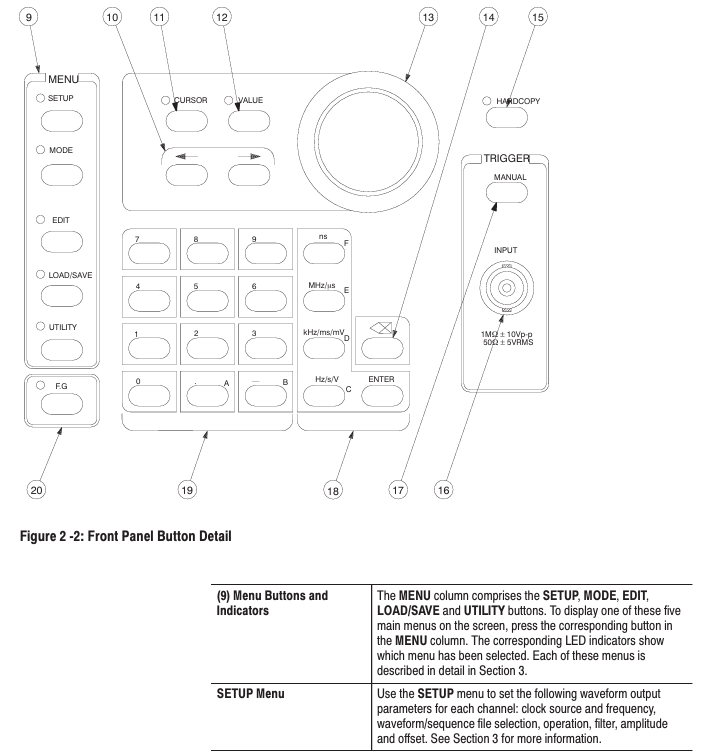
2. Key components of the front-end panel
Specific functional operation examples for component categories
MEAS key in function selection area: switch measurement function; F. G key: Switch to function generator mode and press F. G key to enter standard waveform settings such as sine/triangle/square wave
Menu Control Area MENU Column: SETUP (Parameter Configuration), MODE (Run Mode), EDIT (Editor), LOAD/SAVE (File Management), UTILITY (System Settings) Press the EDIT key to enter the initial menu for file editing
Universal knobs in the data operation area: adjust values/select files; Numerical keys (0-9/.+-): input parameters; Unit key (ns/MHz, etc.): Enter the "1"+"MHz" key to specify the unit and set the clock frequency to 1 MHz
Trigger control area TRIGGER INPUT: external trigger input (maximum ± 10 V ₚ₋ₚ); MANUAL key: Manually triggered. In Triggered mode, press the MANUAL key to trigger waveform output once
Output control area CH1/CH2 ON/OFF keys: switch channel output; SYNC/MARK output interface: Sync/Mark signal output. Press the CH1 ON/OFF button, and the LED will light up to indicate that the CH1 waveform output is turned on
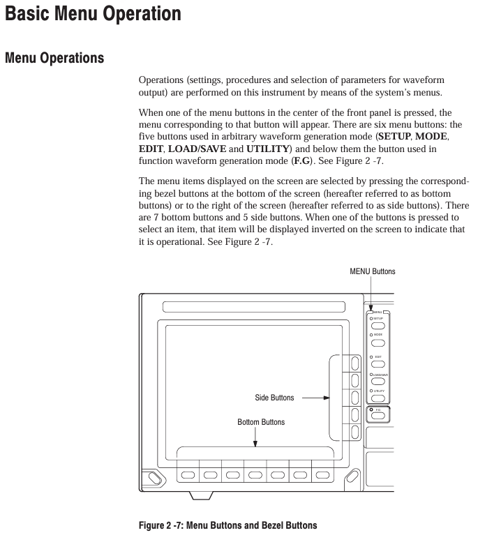
Core functional module: Editor and menu configuration
1. Four core editors (EDIT menu)
(1) Waveform Editor (. WFM file)
Function: Create/edit waveform data, supports 3 display formats:
Graphic display: Visualize waveforms, support point drawing, smoothing (spline/linear interpolation), arithmetic operations (absolute value/integral/derivative).
Timing display: Display timing according to data bits (DATA 11-DATA 0), supporting the setting of - pattern (such as NRZ/NRZI encoding).
Table display: Display each point data in binary/hexadecimal/real form, supporting direct editing of numerical values.
Key operations: Select the editing area (left and right vertical cursor), perform cutting/copying/pasting, or insert other waveform files.
(2) Equation Editor (. QU file)
Function: Generate waveforms through mathematical equations, support 100 line equations, compile and generate WFM file.
Support functions: trigonometric functions (sin/cos), exponents (exp), logarithms (log/ln), random numbers (rnd), differentials (diff), integrals (integ), etc.
Example equation: range (0,1ms) sin (2 * pi * x) (generates a single period sine wave within 0-1ms).
(3) Sequence Editor (. SEQ file)
Function: Combine multiple waveform/sequence files and set the number of repetitions for each file (1-65535 times).
Operation process: Select a file from the directory → Set the number of repetitions → Generate a sequence, support "Show Overview" preview of combined waveforms.
(4) Automatic Step Editor (. AST file)
Function: Program waveforms and output parameters (clock/amplitude/filter) step by step, switch one step per trigger, supporting 100 steps.
Features: In AutoStep mode, the SETUP menu parameters cannot be modified, and the parameters between steps can be independently set (such as Step 1 amplitude of 2V, Step 2 amplitude of 3V).
2. Extended Editor (Option 09)
Editor Type Function Key Parameters
FFT editor for frequency domain editing, supporting fast Fourier transform/inverse transform window functions: 6 types including rectangle, Hanning, and Hamming; Filtering: low-pass/high pass/band-pass/bandstop
Convolutional waveform editor supports high-speed convolution/correlation operations with a maximum of 32000 data points, where the number of result points equals the sum of two waveform points
3. Key menu configuration
(1) SETUP menu (output parameter settings)
Parameter Category Configuration Options Value Range/Description
Clock source: Internal/External; Frequency (Internal) 10.00 Hz -250.0 MHz (4-digit accuracy)
Waveform Sequence (file selection) supports selecting waveform/sequence files WFM/. SEQ file, automatically loads corresponding parameters
CH1 Operation: Normal/AM/Add/External AM AM: CH1 × CH2; Add: CH1+CH2 (1/5 CH2 weight)
Filter Through/1/5/20/50 MHz suppresses high-frequency noise, such as 50 MHz filtering, which is suitable for high-frequency waveforms
Amplitude: Vertical axis full bias voltage of 0.05 V -5 V (50 Ω load, 1 mV step)
Offset Vertical axis offset voltage -2.5 V -+2.5 V (5 mV step size)
(2) MODE menu (operating mode)
Mode name function triggering conditions
Cont (continuous mode) continuously outputs waveforms without triggering, select and run
Triggered mode outputs a waveform every time it is triggered. External trigger (rising/falling edge) or MANUAL key is used
When the gate signal is valid, output waveform external signals (high/low level) or press and hold the MANUAL key
Burst mode: After triggering, output the specified number of waveform bursts 1-65535 times, triggered externally or with the MANUAL key
Waveform Advance switches to the next waveform every time it is triggered, ignoring the number of repetitions in the sequence file and cyclically outputting in order
Press AutoStep AST file step output, with independent parameters for each step and execution of one step per trigger, supporting 100 steps
Data Management and Transmission (LOAD/SAVE menu)
1. Storage medium and capacity
Storage Type Capacity Characteristics
Internal memory (RAM) up to 400 files lost due to power failure, used for temporary editing/output
NVRAM (non-volatile memory) 512KB, up to 400 files can be saved in case of power failure, suitable for long-term storage of critical files
3.5-inch floppy disk is compatible with MS-DOS format and supports directory hierarchy. It needs to be formatted first (UTILITY menu)
2. File loading/saving operations
Load file
Press the LOAD/SAVE key → select Device → select the target media (Disk/NVRam/GPIB).
Select Load → Select 'Load All' or individual file → Confirm loading into internal memory.
Save file
Press the LOAD/SAVE key → select Device → select the target medium.
Select Save → Select "Save All" or individual file → Optional ASCII format for external analysis.
3. GPIB direct transmission
Supported devices: Tek TDS series oscilloscope, HP 54600 series oscilloscope, etc. (refer to Table 3-19).
Operation steps:
Connect AWG2021 to the source device using GPIB cable.
Select Device → GPIB → Select Source Device (such as "Tek TDS CH1").
Select Load ->Automatically load waveform into internal memory (named as "TDSCH1. WFM").
Calibration and maintenance
1. Self calibration process
Trigger condition:
Regular: once every 90 days when the environment is stable (± 2 ℃); When the fluctuation is greater than 5 ℃, once every 30 days.
Manual: Press and hold the CAL key when turning on, or UTILITY → Calibration → Start.
Steps:
Disconnect all probes, the instrument displays "CALIBRATION...".
Internal calibration of ADC and reference source (approximately 2 minutes), complete display of "CAL PASS".
If 'CAL FAIL', check the ambient temperature (+18 ℃ -+28 ℃) and recalibrate.
2. Common troubleshooting
Possible causes and solutions for the fault phenomenon
No display/power adapter failure, fuse blown, replace with 12V/3A adapter; Check the 2A/250V fuse (Rear panel)
The waveform has no inflection point (such as the breakdown voltage test of the Zener transistor), the vertical sensitivity is insufficient, and the filter gear is improper. The vertical sensitivity is set to 1 μ A/div (leakage current measurement), and MAG X10 is turned on; Select a 50 MHz filter
GPIB transmission checksum error, loose cable, incorrect command format, replace GPIB cable (total length ≤ 20m); Confirm that the command termination symbol (EOI/LF) is consistent with the device
Appendix Key Content
Appendix A (Options and Accessories): Detailed description of hardware specifications and connection methods for options such as Option 02 (2-channel) and Option 03 (ECL output).
Appendix B (Performance Characteristics): Electrical characteristics (such as clock frequency accuracy ± 10 ppm), mechanical characteristics (weighing approximately 10kg), environmental characteristics (storage humidity 10% -90%).
Appendix C (Performance Verification): Includes testing procedures for clock frequency/amplitude accuracy/pulse response, etc., which require the use of a standard signal source and oscilloscope.
Appendix D (Sample Waveform Library): Provides formulas and parameters for preset waveforms such as Gaussian pulses, Lorentz pulses, DQPSK signals, etc.
- YOKOGAWA
- Reliance
- ADVANCED
- SEW
- ProSoft
- WATLOW
- Kongsberg
- FANUC
- VSD
- DCS
- PLC
- man-machine
- Covid-19
- Energy and Gender
- Energy Access
- Renewable Integration
- Energy Subsidies
- Energy and Water
- Net zero emission
- Energy Security
- Critical Minerals
- A-B
- petroleum
- Mine scale
- Sewage treatment
- cement
- architecture
- Industrial information
- New energy
- Automobile market
- electricity
- Construction site
- HIMA
- ABB
- Rockwell
- Schneider Modicon
- Siemens
- xYCOM
- Yaskawa
- Woodward
- BOSCH Rexroth
- MOOG
- General Electric
- American NI
- Rolls-Royce
- CTI
- Honeywell
- EMERSON
- MAN
- GE
- TRICONEX
- Control Wave
- ALSTOM
- AMAT
- STUDER
- KONGSBERG
- MOTOROLA
- DANAHER MOTION
- Bentley
- Galil
- EATON
- MOLEX
- Triconex
- DEIF
- B&W
- ZYGO
- Aerotech
- DANFOSS
- KOLLMORGEN
- Beijer
- Endress+Hauser
- schneider
- Foxboro
- KB
- REXROTH
- YAMAHA
- Johnson
- Westinghouse
- WAGO
- TOSHIBA
- TEKTRONIX
- BENDER
- BMCM
- SMC
- HITACHI
- HIRSCHMANN
- XP POWER
- Baldor
- Meggitt
- SHINKAWA
- Other Brands
- UniOP
- KUKA
- IBA
- Beckhoff
-
ADLINK CPCI-6860A - 51-31310-OB10 industrial motherboard CompactPCI SBC
-
ADLINK AmITX-SL-G-H110 - 51-7A104-0A30 Mini-ITX Industrial Motherboard
-
ADLINK PXI-2005-003 - CPCI Industrial PC Data Acquisition Card Multi-Function DAQ
-
ADLINK DININ-814M - 51-14032-0A3D SCSI-100P cable connection Interface Terminal Board
-
ADLINK CPCI-3920NA/C2D15/M1G - 3U CompactPCI Intel Core 2 Duo Single Board Computer
-
ADLINK PCIE-8560 - 51-18014-0A20 Communication Card High Speed DAQ
-
ADLINK PCI-C154+ - Motion Control Card 4-axis Motion Controller Board
-
ADLINK PCI-RTV24 - image capture card Analog Video Frame Grabber
-
ADLINK NuPRO-842LV/P - 51-41360-0B30 Industrial Motherboard CPU Board
-
ADLINK cBP-3208/3208R - CPCI Board 3U 8-Slot CompactPCI Backplane
-
ADLINK PCI-8164 - 4-Axis Motion Controller PCI Card 51-12406-0A40
-
ADLINK PCIe-GIE64+ - 4-CH GigE Vision PoE+ Frame Grabber Video Capture Card
-
ADLINK CPCI-6860 / 6860A - CompactPCI Dual Xeon Single Board Computer
-
ADLINK IEC-915GV - REV 1.1 Industrial motherboard CPU Board
-
ADLINK ND-6520 - Technology RS-232 to RS-422RS-485 Converter NuDAM Module
-
ADLINK RTV-24 / PCI-MP4S - 51-12519-1C30 4-Channel Real Time Video Capture Board
-
ADLINK cPCI-6910 / cPCI-6910AM/M1G - cPCI-6910AM/DXL16/M1G/S80G(G)-3120 BOARD CompactPCI SBC
-
ADLINK NUPRO-A40H - Linghua 51-41807-1A30 Industrial Control Computer Motherboard
-
ADLINK USB-3488A - USB to GPIB INTERFACE USB-3488A(G) Controller Module
-
ADLINK PCI-8134A - motion control card 4-Axis Controller Card
-
ADLINK PCI-7432 - Board 32-Channel input / 32-output Isolated Digital I/O PCI Card
-
ADLINK PCI-8134A - 51-12421-0A10 motion controller card tested
-
ADLINK LPCIe-7230 - 32 CH Isolated Input/output Card 2 Interrupts Low Profile PCIe
-
ADLINK NuPRO-E340 - industrial computer motherboard 51-47807-0A30 PICMG 1.3 SHB
-
ADLINK PCI-7434 - High-speed Digital Acquisition Card 64-CH Isolated DO Card
-
ADLINK NuPRO-E330 - 51-41805-0A20 Indsutrial Board SHB Single Board Computer
-
ADLINK PCI-7248 - OPTO-22 48 CHANNEL DIO DIGITAL TTL/DTL I/O 51-12006-0A40 GP
-
ADLINK PCI-8134 - Motion control card 4-Axis Controller Card
-
ADLINK AMP-208C - Movimiento Control Tarjeta 51-12420-1A20 W/Expansión & Breakout
-
ADLINK PCI-8164 - 51-12406-0A40 PCB Board 4-Axis Motion Controller Card
-
ADLINK DIN-68Y-SGII / DIN-68M-J3A - Terminal Board Connector Interface Block
-
ADLINK PCIe-7432 - Technology 51-18402-0A10 PCIe Card With High Input Range
-
ADLINK PCI-8144 / PCI-8144N - Motion control card 4-Axis Stepper Controller Card
-
ADLINK HSL-HUB3/REPEATER - HIGH SPEED LINK EXTENSION MODULES Distributed Hub Module
-
ADLINK ND-6017 - Data Logging + Acquisition 8CH A/D input Mod NuDAM Module
-
ADLINK LPCIe-7250 - data acquisition card Low Profile 8-CH Relay Output Card
-
ADLINK PCI-7432 - I/O card 64-CH Isolated Digital Input Output PCI Card
-
ADLINK IMB-M43H - industrial control computer motherboard Q87 Chip Micro-ATX
-
ADLINK MP-C154 - Motion control Card 4-Axis Motion Controller Board
-
ADLINK PCI-RTV24 - image capture card Video Frame Grabber Card
-
ADLINK PCI-7250 - 8-CH Relay Output & 8-CH Isolated DI Card
-
ADLINK PCI-6308V - 8-CH 12-Bit Isolated Analog Output PCI Card PCB-I-E-1148=6EX2
-
ADLINK PCI-7248 - capture card 48-CH Opto-22 Compatible DIO Card
-
ADLINK HSL-AI16A02-M-VV - Analog Input Output Distributed Module
-
ADLINK NuPRO-A301 - Rev:1.4 NUPRO-A301 PICMG Full-Size Single Board Computer
-
ADLINK PCI-6208V-GL - 8-CH Voltage Analog Output PCI Card
-
ADLINK PCI-8134A - 51-12421-0A10 4-Axis Motion Controller Card
-
ADLINK MNET-S23 - TECHNOLOGY MNET S23 - SERVO DRIVER CONTROL MODULE
-
ADLINK M-342 - ATX I3 I5 I7 Q67 Industrial Motherboard
-
ADLINK NUPRO-780 - Industrial Motherboard CPU Board PICMG SBC
-
ADLINK MP-C154 / MP-C152 - 4-Axis Motion Control Card Pulse-Train Controller
-
ADLINK NuPRO-935A/LV10B0 - Motherboard 51-41802-0A10 GP w/RAM Industrial Control Board
-
ADLINK MP-C154 - Motion control card 4-Axis Motion Controller Mainboard
-
ADLINK PCI-7250 - PCI Acquisition Card 8-CH Relay Output Isolated DI Card
-
ADLINK ACL-7124 - Technology Inc.24 DIO Card Digital Input Output Card
-
ADLINK PCI-8554 A2 - Timer/Counter Data Acquisition Card
-
ADLINK DIN-825-GP4 - Terminal Block Interface Board Breakout Module
-
ADLINK NuPR0-761 - REV:1.1 Industrial motherboard Full-Size PICMG SBC
-
ADLINK MXE-1401/M8G (G) - Matrix Fanless Embedded Computer Industrial PC
-
ADLINK HSL-DI16DO16-UD-NN - Digital 16 Channel I/O Mod Distributed I/O Module
-
ADLINK ND6520 - NUDAM INTELLIGENT DA&C MODULE RS232-RS-422/RS485 CONVERTOR
-
ADLINK NUPRO-761 - REV:1.1 Industrial Motherboard CPU Board
-
ADLINK AMP-208C - Motion Control Card 51-12420-1A20 DSP-based 8-axis
-
ADLINK NuPRO-A301REV 1.4 - with packaging industrial computer motherboard PICMG SBC
-
ADLINK PCM-9112+ - 51-12300-0A2 industrial motherboard Multi-Function DAQ PC/104 Module
-
ADLINK PCM-7250+ - 8-CH Relay Outputs & 8-CH Isolated DI Module PC/104
-
ADLINK PCI-RTV24 - Image capture card Analog Video Frame Grabber
-
ADLINK PCI-8134 - Motion Controller PCI Card 4-Axis Controller Board
-
ADLINK PCI-7432 - Isolated Digital I/O PCI Card
-
ADLINK PCI-8554 A2 - acquisition card Timer/Counter Card
-
ADLINK PCI-8132 - Rev.A2 2-Axis Servo & Stepper Motion Controller Card
-
ADLINK PCI-8132 - Data Acquisition card 2-Axis Motion Controller Card
-
ADLINK EBP-13E4 - 51-46703-0A30 Industrial Backplane Board Passive Backplane
-
ADLINK PCI-800L - Electronic Card Interface Controller Card
-
ADLINK PCIe-GIE72 - 51-18531-0A10 PCB Board GigE Vision Frame Grabber
-
ADLINK DAQ-2010(G)-OOBO - Simultaneous-Sampling Multi-Function DAQ Card
-
ADLINK PCI-9112 - REV.B1 Multifunction DAQ Card Data Acquisition Card
-
ADLINK PCI-7230 - 51-12003-DA60 32-CH Isolated Digital I/O Card
-
ADLINK PCI-7432 - Data Acquisition Card Isolated Digital I/O PCI Card
-
ADLINK ETX-AT-N270-18/LXE - 51-71111-0A20 ETX CPU Module Motherboard
-
ADLINK HSL-DI32-UD-N - DIGITAL INPUT 32 POINTS MODULE Distributed I/O
-
ADLINK AMP-204C - Motion Control card DSP-Based 4-Axis Advanced Controller
-
ADLINK MNET-4XMOG-0050 - Four-axis Motion Controller Distributed Motion Module
-
ADLINK AMP-204C - Motion control card DSP-Based 4-Axis Pulse-Train Controller
-
ADLINK PCI-7442 - Switch card 64-Channel Datalogging & Acquisition Card
-
ADLINK M-302 - Industrial control motherboard ATX PC Board
-
ADLINK NUPRO-852 / NUPRO-852LV - Industrial motherboard Single Board Computer
-
ADLINK PCI-8134 - REV.B1. 4-Axis Motion Controller Card
-
ADLINK PCI-GIE62 + - 51-18502-0A20 2-CH GigE Vision Frame Grabber PoE Card
-
ADLINK PCI-MPG24 - 51-12523-0B20 MPEG4 Card Video Compression Hardware
-
ADLINK HSL-TB32-M-DIN - 32-CH I/O TERMINAL W/ HSL-AI16AO2-M-VV MODULE
-
ADLINK PCI-M114-GL - PCB Ver 2.1 Motion Controller Axis Card
-
ADLINK IMB-M40H - SYM76996H61 motherboard Industrial Computer Mainboard
-
ADLINK NUPRO-A40H - 51-41807-1A20 industrial control motherboard H61 Chip
-
ADLINK PCI-M114-GL - Axis Card Data Acquisition Card PCB VER2.2 Motion Controller
-
ADLINK PCI-8134 - Motion Controller PCI Card 4-Axis Controller Board
-
ADLINK PCI-8102 - Motion control card 2-Axis Servo & Stepper Controller
-
ADLINK NuPRO-841REV:3.0 - motherboard Industrial Control PC Board
-
ADLINK HSL-TB32-U-DIN REV A1 - Breakout Terminal Board Field I/O Module
-
ADLINK AMP-204C - Motion Control card DSP-Based 4-Axis Pulse-Train Controller
-
ADLINK NUPRO-A40H - 51-41807-1A20 industrial control motherboard H61 PC Board
-
ADLINK PCI-6308A / PCI-6308V - 51-12202-0A50 Isolated Analog Output Card
-
ADLINK AMP-204C - DSP-Based 4-Axis Advanced Pulse-Train Motion Controller
-
ADLINK PCI-7434 - Technology 64-Channel Isolated Digital I/O PCI Cards
-
ADLINK CPCI-6840 / CPCI-6840V / PM16/M1G-12G0 - CompactPCI Single Board Computer CPU Module
-
ADLINK PCIE-GIE74 - Motherboard Video Capture Card 51-18531-0A10 Frame Grabber
-
ADLINK NuPRO-E330 - industrial computer equipment motherboard Control Mainboard
-
ADLINK AMP-208C / 51-12420-1A20 - Motion Control Card W/ Expansion & Breakout Board
-
ADLINK HPCI-14S12U - industrial computer baseboard Passive Backplane 14 Slots
-
ADLINK PCI-8164 - 4-Axis Motion Controller PCI Card W/ 1x Cable, 1x Breakout Box
-
ADLINK PCIe-RTV24 - 51-18016-0A20 Image Acquisition Video Capture Card
-
ADLINK M-342 - 5 PCI ATX Motherboard Industrial PC Mainboard
-
ADLINK PCI-FIW64 - 4/2 Channel IEEE1394B Image Capture Card FireWire Frame Grabber
-
ADLINK PCI-7432 - digital IO card 64-CH Isolated Digital Input Output Card
-
ADLINK 51-12001-0C20 - Circuit Board PCI-7200 Data Acquisition Controller Card
-
ADLINK PXI-3920 - PXI 3U cPCI Industrial Controller Embedded System CPU Board
-
ADLINK NuPRO-841REV:2.0 - motherboard Industrial Control PC Board
-
ADLINK NuPro-E330 - 51-41805-0A20 PCB Industrial Control Computer Motherboard
-
ADLINK PCI-RTV24 - Image capture card Analog Video Frame Grabber
-
ADLINK PCI-7442 - Switch card 64-Channel Datalogging & Acquisition Card
-
ADLINK HPX-13S4 - device baseboard Passive Backplane Riser Card
-
ADLINK PCI-9112 REV A.1 - Multi Function DA&C Board Data Acquisition Card
-
ADLINK PCI-7248 - 51-12006-0A40 Card Control 48-CH Digital I/O Module
-
ADLINK CPCI-6860 / 6860A - motherboard CompactPCI Dual Xeon Single Board Computer
-
ADLINK DPAC-3020-11(G) - Embedded PC Automation Controller Machine Control Board
-
ADLINK NuPRO-841 REV:1.0 - industrial control motherboard CPU Board
-
ADLINK MNET-4XMOG-0050 - Four-axis Motion Controller MNET Motion Control Card
-
ADLINK ETX-AT-N270-18/LXE - 51-71111-0A20 ETX CPU Module Motherboard

K-JIANG

Add: Jimei North Road, Jimei District, Xiamen, Fujian, China
Tell:+86-15305925923