
K-WANG


Tektronix AWG70000 series arbitrary waveform generator
Compliance certification: Complies with EN 61010-1, UL 61010-1, CSA C22.2 No. 1010.1 safety standards to ensure compliance in industrial use.
Tektronix AWG70000 series arbitrary waveform generator
Product Overview
Product coverage: AWG70000 series full models (such as AWG70001 single channel, AWG70002 dual channel), supporting software version 7.0 and above.
Compliance certification: Complies with EN 61010-1, UL 61010-1, CSA C22.2 No. 1010.1 safety standards to ensure compliance in industrial use.
Remote control setup: Ethernet and GPIB
1. Ethernet control (recommended)
(1) Hardware connection
Connect the Ethernet port of the instrument Rear panel to the LAN switch/PC using an RJ-45 Ethernet cable, supporting speeds of 10BASE-T (10Mbps), 100BASE-TX (100Mbps), and 1000BASE-T (1Gbps).
(2) Protocol and Configuration
Protocol type requirements for application scenarios
VXI-11 Server instrument and PC are both equipped with TekVISA standard remote control, with strong compatibility
Both the Raw Socket instrument and PC are equipped with TekVISA high-speed data transmission and low latency
DHCP is enabled by default for IP acquisition, and the IP is automatically obtained from the router. If a fixed IP is required, the laboratory's fixed network environment can be modified through Windows network settings
2. GPIB control (compatible with traditional devices)
(1) Hardware connection
Instrument Rear panel USB 2.0 HS Device port → connect to the host port of TEK-USB-488 adapter;
Connect the GPIB port of the adapter to the GPIB card/interface of the PC using a GPIB cable.
(2) Key configuration rules
Address uniqueness: Each device on the bus must be assigned a unique address (1-30), which cannot be duplicated;
Bus limitation: Up to 15 devices can be connected, with 1 device required every 2 meters (6 feet), and the total cable length should be ≤ 20 meters (65 feet);
Power requirement: At least 2/3 of the equipment should be powered on to avoid signal attenuation;
Topology: Only supports star or linear connections, and prohibits ring/parallel connections.
(3) Address modification steps
Instrument end: Go to Utilities → System → GPIB Address, set a new address (default 1);
Restart adapter: Disconnect and reconnect the TEK-USB-488 adapter to ensure the new address takes effect.
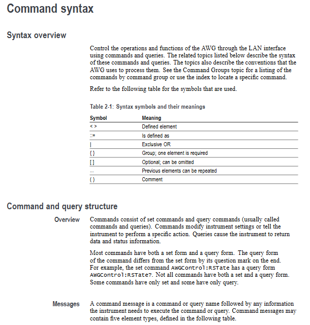
Command syntax specification: SCPI standard and execution mechanism
1. Core grammatical symbols
Example of symbol meaning
<>Defined element (required)<wfm_name>(waveform name)
Defined as<Block>::=#<NZDig><Dig>... (Block Data Definition)
`XOR (choose one) ON OFF (choose one)
{} Required group (choose one) ` {INTernal EXTernal} ` (required internal/external)
[] Optional section [:]<Header>(colon optional)
... The preceding elements can be repeated<Argument>[,<Argument>...] (multi parameter)
() Comment #<NZDig>(non-zero digits)
2. Command and Query Structure
(1) Command (modify settings/execute actions)
Format: [:]<Header>[<Space><Argument>[<Comma><Argument>...]
Example: CLOCk: SURce INTernal (set clock source to internal)
(2) Query (Get Status/Data)
Format: [:]<Header>? [<Space><Argument>[<Comma><Argument>...]]
Example: CLOCk: SURce? (Query the current clock source)
3. Parameter types and rules
Example of Parameter Type Description
Boolean 0/OFF (false), 1/ON (true) AWGControl: DLOading: ENABle 1 (enable dynamic loading)
Discrete fixed options (such as MIN/MAX) FGEN: CHANnel1: AMPCrude MAX (amplitude set to maximum)
Numerical values (NR1/NR2/NR3/NRf) NR1 (integer, such as 123), NR2 (decimal, such as 12.3), NR3 (scientific counting, such as 1.23E3), NRf (flexible format) CLOCk: SRATE 25E9 (sampling rate 25GS/s)
String needs to be enclosed in single/double quotes MMEMory: OPEN "C: waveform. wfmx" (load file)
Arbitrary Block: Binary data block in the format of #<NZDig><Dig>...<DChar>... WLILD: WAVeform: DATA "TestWfm", # 41024xxxx... (transmitting 1024 points of data)
4. Command execution mechanism
(1) Three types of commands
Example of Type Characteristics
Execute the next command OUTPut1: STATe ON only after the previous command is completed; OUTPut2: STATe ON (First turn on CH1, then turn on CH2)
During the execution of the blocking command, other commands are prohibited, which takes a long time. CALibration [: ALL] (full calibration, waiting for completion)
Overlapping commands can be executed concurrently with other commands, and it is necessary to manually ensure the completion of DIAGnostic: STARt (diagnostic startup, requires OPC)? Confirmation completed)
(2) Key Execution Rules
Abbreviation rule: Commands can be abbreviated, with the capitalized part being the abbreviation core (such as TRIGger: LEVel → TRIG: LEV);
Splicing rules: Use; Splicing multiple commands, different root nodes need to add: (such as TRIG: SUR EXT; :SOUR1:RMODe TRIG);
Termination symbol: When sending commands, EOI (last byte assertion) should be used as the termination symbol, and the instrument response should be terminated with LF+EOI;
Clear command: * CLS clears all event registers and queues, Device Clear (DCL) resets the command reception status.
Detailed explanation of core command group (selected high-frequency group)
1. Clock group (CLOCk): controls sampling rate and synchronization
Example of Command Function Parameter Range
CLOCk: SURce sets clock sources INTernal (internal), EFIXed (external fixed 10MHz), EVAReliable (external variable), EXTernal (external clock input) CLOCk: SURce EXTernal
CLOCk: Set the sampling rate AWG70001:1.49kS/s-50GS/s for SRATE; AWG70002:1.49kS/s-25GS/s CLOCk:SRATe 25E9(25GS/s)
CLOCk: PHASe: AJust: DEGREEs phase adjustment (degrees) -10800 °~10800 ° CLOCk: PHASe: AJust 90 (adjusted by 90 degrees)
CLOCk: JITTer jitter suppression switch 0/OFF, 1/ON CLOCk: JITTer ON (enable jitter suppression)
2. Sequence group (SLISt): Create multi-step waveform sequences
(1) Example of Core Command
Create sequence: SLISt: Sequence: NEW "Seq1", 10,2 (Create "Seq1", 10 steps, 2 tracks);
Set the number of steps to be repeated: SLISt: Sequence: STEP1: RCCount 5 (repeat Step 1 5 times);
Assign waveforms to steps: SLISt: Sequence: STEP1: TASSet1: WAVeform "Sine1" (Step 1 assigns "Sine1" waveform to track 1);
Query sequence length: SLISt: SEQ: LENGth? Seq1 "(returns the total number of steps taken by Seq1).
(2) Key Limitations
Maximum steps: 16383 steps per sequence;
Maximum number of tracks: 8 tracks per sequence;
Maximum number of repetitions per step: 1048576.
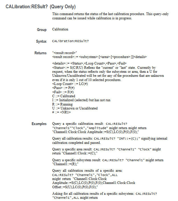
3. CALibration: Ensure measurement accuracy
Command function precautions
CALibration [: ALL] executes full calibration blocking command, cannot be aborted, returns 0 (success)/-340 (failure) upon completion
CALibration: To restore factory calibration constants, enter calibration active mode (ACTive: MODE CALibration)
CALibration:LOG? Query calibration log with timestamp and result (PASS/FAIL), maximum 64K characters
CALibration:RUNNing? Querying the current calibration process returns' Subsystem: Region: Step '(e.g.' Channel1: Dc: Compliance ')
4. S-parameter group (WLイ: PARAMeter): signal integrity optimization
(1) Mode switching
Command: WLVNet: PARAMeter: MODE {CASC | NCAS} (CASC=Cascade, NCAS=Non Cascade);
Cascade mode: Supports cascading up to 6 S-parameter files, suitable for complex links;
Non cascading mode: only 1 S parameter file, suitable for simple links.
(2) Port configuration (taking non cascaded as an example)
Command: WLVNet: PARAMeter: NCASCAding: TYPE 4 (set to port 4);
Signal type: WLVNet: PARAMeter: NCASCAding: TYPE {VICTim | AGGRessor | BOTH} (victim/interferer/both);
Embedding: WLILD: PARAMeter: NCASCAding: DEEMBed 1 (Enable embedding to correct link loss).
Status and Event System: Monitoring Instrument Operation
1. Four major register groups
(1) Status Byte Register (SBR)
Function: Summarize all 8-bit registers of states through * STB? Query;
Key position definition:
Bit7 (OSS): Operation status summary (events after OENR mask);
Bit6 (MSS/RQS): Main status summary (with service requests);
Bit5 (ESB): Standard Event Summary (SESR has new events);
Bit4 (MAV): Message available (output queue with data);
Bit3 (QSS): Suspicious Status Summary (Events after QENR Mask).
(2) Standard Event Status Block (SESB)
Contains two registers:
SESR (Standard Event Status Register): Record power, error, and other events through ESR? Query;
ESER (Event Status Enable Register): Mask SESR events, set through * ESE.
SESR key position:
Bit7 (PON): Power on;
Bit5 (CME): Command error (such as syntax error);
Bit4 (EXE): Execution error (such as parameter out of range);
Bit0 (OPC): Operation completed (triggered by OPC command).
2. Two types of queues
(1) Output queue
Function: FIFO structure, storing response data for query commands;
Trigger condition: After the query is executed, the data is stored in the queue, and the MAV bit of SBR is set to 1;
Clearing rule: Automatically clear when receiving new commands/queries, unread data will result in errors.
(2) Event queue
Function: FIFO structure, storing instrument events (errors, status changes, etc.);
Capacity limit: Up to 32 events, if exceeded, replace the 32nd event with -350, "Queue Overflow";
Query method: SYSTem: ERRor [: NEXT]? (Read the next one) SYSTem:ERRor:ALL? (Read all).
Appendix Key Content
1. Appendix A: Character Table
A hexadecimal/decimal value that covers 7 ASCII characters, including control characters (such as LF=0A hex) and printable characters (such as A=41 hex), used as a character encoding reference for command transmission.
2. Appendix B: Original Socket Specification
Define communication parameters for the Raw Socket protocol:
Port number: 5025 (default);
Data format: ASCII, with each line terminated by n;
Timeout setting: It is recommended that the client set a 10 second timeout to avoid disconnection.
3. Appendix C: Factory Initialization Settings
List the default values for all parameters, such as:
Clock source: INTernal;
Sampling rate: AWG70001=50GS/s, AWG70002=25GS/s;
Trigger mode: ASYNChronous;
Output status: OFF (all channels are closed).
- YOKOGAWA
- Reliance
- ADVANCED
- SEW
- ProSoft
- WATLOW
- Kongsberg
- FANUC
- VSD
- DCS
- PLC
- man-machine
- Covid-19
- Energy and Gender
- Energy Access
- Renewable Integration
- Energy Subsidies
- Energy and Water
- Net zero emission
- Energy Security
- Critical Minerals
- A-B
- petroleum
- Mine scale
- Sewage treatment
- cement
- architecture
- Industrial information
- New energy
- Automobile market
- electricity
- Construction site
- HIMA
- ABB
- Rockwell
- Schneider Modicon
- Siemens
- xYCOM
- Yaskawa
- Woodward
- BOSCH Rexroth
- MOOG
- General Electric
- American NI
- Rolls-Royce
- CTI
- Honeywell
- EMERSON
- MAN
- GE
- TRICONEX
- Control Wave
- ALSTOM
- AMAT
- STUDER
- KONGSBERG
- MOTOROLA
- DANAHER MOTION
- Bentley
- Galil
- EATON
- MOLEX
- Triconex
- DEIF
- B&W
- ZYGO
- Aerotech
- DANFOSS
- KOLLMORGEN
- Beijer
- Endress+Hauser
- schneider
- Foxboro
- KB
- REXROTH
- YAMAHA
- Johnson
- Westinghouse
- WAGO
- TOSHIBA
- TEKTRONIX
- BENDER
- BMCM
- SMC
- HITACHI
- HIRSCHMANN
- XP POWER
- Baldor
- Meggitt
- SHINKAWA
- Other Brands
- UniOP
- KUKA
- IBA
- Beckhoff
-
ADLINK CPCI-6860A - 51-31310-OB10 industrial motherboard CompactPCI SBC
-
ADLINK AmITX-SL-G-H110 - 51-7A104-0A30 Mini-ITX Industrial Motherboard
-
ADLINK PXI-2005-003 - CPCI Industrial PC Data Acquisition Card Multi-Function DAQ
-
ADLINK DININ-814M - 51-14032-0A3D SCSI-100P cable connection Interface Terminal Board
-
ADLINK CPCI-3920NA/C2D15/M1G - 3U CompactPCI Intel Core 2 Duo Single Board Computer
-
ADLINK PCIE-8560 - 51-18014-0A20 Communication Card High Speed DAQ
-
ADLINK PCI-C154+ - Motion Control Card 4-axis Motion Controller Board
-
ADLINK PCI-RTV24 - image capture card Analog Video Frame Grabber
-
ADLINK NuPRO-842LV/P - 51-41360-0B30 Industrial Motherboard CPU Board
-
ADLINK cBP-3208/3208R - CPCI Board 3U 8-Slot CompactPCI Backplane
-
ADLINK PCI-8164 - 4-Axis Motion Controller PCI Card 51-12406-0A40
-
ADLINK PCIe-GIE64+ - 4-CH GigE Vision PoE+ Frame Grabber Video Capture Card
-
ADLINK CPCI-6860 / 6860A - CompactPCI Dual Xeon Single Board Computer
-
ADLINK IEC-915GV - REV 1.1 Industrial motherboard CPU Board
-
ADLINK ND-6520 - Technology RS-232 to RS-422RS-485 Converter NuDAM Module
-
ADLINK RTV-24 / PCI-MP4S - 51-12519-1C30 4-Channel Real Time Video Capture Board
-
ADLINK cPCI-6910 / cPCI-6910AM/M1G - cPCI-6910AM/DXL16/M1G/S80G(G)-3120 BOARD CompactPCI SBC
-
ADLINK NUPRO-A40H - Linghua 51-41807-1A30 Industrial Control Computer Motherboard
-
ADLINK USB-3488A - USB to GPIB INTERFACE USB-3488A(G) Controller Module
-
ADLINK PCI-8134A - motion control card 4-Axis Controller Card
-
ADLINK PCI-7432 - Board 32-Channel input / 32-output Isolated Digital I/O PCI Card
-
ADLINK PCI-8134A - 51-12421-0A10 motion controller card tested
-
ADLINK LPCIe-7230 - 32 CH Isolated Input/output Card 2 Interrupts Low Profile PCIe
-
ADLINK NuPRO-E340 - industrial computer motherboard 51-47807-0A30 PICMG 1.3 SHB
-
ADLINK PCI-7434 - High-speed Digital Acquisition Card 64-CH Isolated DO Card
-
ADLINK NuPRO-E330 - 51-41805-0A20 Indsutrial Board SHB Single Board Computer
-
ADLINK PCI-7248 - OPTO-22 48 CHANNEL DIO DIGITAL TTL/DTL I/O 51-12006-0A40 GP
-
ADLINK PCI-8134 - Motion control card 4-Axis Controller Card
-
ADLINK AMP-208C - Movimiento Control Tarjeta 51-12420-1A20 W/Expansión & Breakout
-
ADLINK PCI-8164 - 51-12406-0A40 PCB Board 4-Axis Motion Controller Card
-
ADLINK DIN-68Y-SGII / DIN-68M-J3A - Terminal Board Connector Interface Block
-
ADLINK PCIe-7432 - Technology 51-18402-0A10 PCIe Card With High Input Range
-
ADLINK PCI-8144 / PCI-8144N - Motion control card 4-Axis Stepper Controller Card
-
ADLINK HSL-HUB3/REPEATER - HIGH SPEED LINK EXTENSION MODULES Distributed Hub Module
-
ADLINK ND-6017 - Data Logging + Acquisition 8CH A/D input Mod NuDAM Module
-
ADLINK LPCIe-7250 - data acquisition card Low Profile 8-CH Relay Output Card
-
ADLINK PCI-7432 - I/O card 64-CH Isolated Digital Input Output PCI Card
-
ADLINK IMB-M43H - industrial control computer motherboard Q87 Chip Micro-ATX
-
ADLINK MP-C154 - Motion control Card 4-Axis Motion Controller Board
-
ADLINK PCI-RTV24 - image capture card Video Frame Grabber Card
-
ADLINK PCI-7250 - 8-CH Relay Output & 8-CH Isolated DI Card
-
ADLINK PCI-6308V - 8-CH 12-Bit Isolated Analog Output PCI Card PCB-I-E-1148=6EX2
-
ADLINK PCI-7248 - capture card 48-CH Opto-22 Compatible DIO Card
-
ADLINK HSL-AI16A02-M-VV - Analog Input Output Distributed Module
-
ADLINK NuPRO-A301 - Rev:1.4 NUPRO-A301 PICMG Full-Size Single Board Computer
-
ADLINK PCI-6208V-GL - 8-CH Voltage Analog Output PCI Card
-
ADLINK PCI-8134A - 51-12421-0A10 4-Axis Motion Controller Card
-
ADLINK MNET-S23 - TECHNOLOGY MNET S23 - SERVO DRIVER CONTROL MODULE
-
ADLINK M-342 - ATX I3 I5 I7 Q67 Industrial Motherboard
-
ADLINK NUPRO-780 - Industrial Motherboard CPU Board PICMG SBC
-
ADLINK MP-C154 / MP-C152 - 4-Axis Motion Control Card Pulse-Train Controller
-
ADLINK NuPRO-935A/LV10B0 - Motherboard 51-41802-0A10 GP w/RAM Industrial Control Board
-
ADLINK MP-C154 - Motion control card 4-Axis Motion Controller Mainboard
-
ADLINK PCI-7250 - PCI Acquisition Card 8-CH Relay Output Isolated DI Card
-
ADLINK ACL-7124 - Technology Inc.24 DIO Card Digital Input Output Card
-
ADLINK PCI-8554 A2 - Timer/Counter Data Acquisition Card
-
ADLINK DIN-825-GP4 - Terminal Block Interface Board Breakout Module
-
ADLINK NuPR0-761 - REV:1.1 Industrial motherboard Full-Size PICMG SBC
-
ADLINK MXE-1401/M8G (G) - Matrix Fanless Embedded Computer Industrial PC
-
ADLINK HSL-DI16DO16-UD-NN - Digital 16 Channel I/O Mod Distributed I/O Module
-
ADLINK ND6520 - NUDAM INTELLIGENT DA&C MODULE RS232-RS-422/RS485 CONVERTOR
-
ADLINK NUPRO-761 - REV:1.1 Industrial Motherboard CPU Board
-
ADLINK AMP-208C - Motion Control Card 51-12420-1A20 DSP-based 8-axis
-
ADLINK NuPRO-A301REV 1.4 - with packaging industrial computer motherboard PICMG SBC
-
ADLINK PCM-9112+ - 51-12300-0A2 industrial motherboard Multi-Function DAQ PC/104 Module
-
ADLINK PCM-7250+ - 8-CH Relay Outputs & 8-CH Isolated DI Module PC/104
-
ADLINK PCI-RTV24 - Image capture card Analog Video Frame Grabber
-
ADLINK PCI-8134 - Motion Controller PCI Card 4-Axis Controller Board
-
ADLINK PCI-7432 - Isolated Digital I/O PCI Card
-
ADLINK PCI-8554 A2 - acquisition card Timer/Counter Card
-
ADLINK PCI-8132 - Rev.A2 2-Axis Servo & Stepper Motion Controller Card
-
ADLINK PCI-8132 - Data Acquisition card 2-Axis Motion Controller Card
-
ADLINK EBP-13E4 - 51-46703-0A30 Industrial Backplane Board Passive Backplane
-
ADLINK PCI-800L - Electronic Card Interface Controller Card
-
ADLINK PCIe-GIE72 - 51-18531-0A10 PCB Board GigE Vision Frame Grabber
-
ADLINK DAQ-2010(G)-OOBO - Simultaneous-Sampling Multi-Function DAQ Card
-
ADLINK PCI-9112 - REV.B1 Multifunction DAQ Card Data Acquisition Card
-
ADLINK PCI-7230 - 51-12003-DA60 32-CH Isolated Digital I/O Card
-
ADLINK PCI-7432 - Data Acquisition Card Isolated Digital I/O PCI Card
-
ADLINK ETX-AT-N270-18/LXE - 51-71111-0A20 ETX CPU Module Motherboard
-
ADLINK HSL-DI32-UD-N - DIGITAL INPUT 32 POINTS MODULE Distributed I/O
-
ADLINK AMP-204C - Motion Control card DSP-Based 4-Axis Advanced Controller
-
ADLINK MNET-4XMOG-0050 - Four-axis Motion Controller Distributed Motion Module
-
ADLINK AMP-204C - Motion control card DSP-Based 4-Axis Pulse-Train Controller
-
ADLINK PCI-7442 - Switch card 64-Channel Datalogging & Acquisition Card
-
ADLINK M-302 - Industrial control motherboard ATX PC Board
-
ADLINK NUPRO-852 / NUPRO-852LV - Industrial motherboard Single Board Computer
-
ADLINK PCI-8134 - REV.B1. 4-Axis Motion Controller Card
-
ADLINK PCI-GIE62 + - 51-18502-0A20 2-CH GigE Vision Frame Grabber PoE Card
-
ADLINK PCI-MPG24 - 51-12523-0B20 MPEG4 Card Video Compression Hardware
-
ADLINK HSL-TB32-M-DIN - 32-CH I/O TERMINAL W/ HSL-AI16AO2-M-VV MODULE
-
ADLINK PCI-M114-GL - PCB Ver 2.1 Motion Controller Axis Card
-
ADLINK IMB-M40H - SYM76996H61 motherboard Industrial Computer Mainboard
-
ADLINK NUPRO-A40H - 51-41807-1A20 industrial control motherboard H61 Chip
-
ADLINK PCI-M114-GL - Axis Card Data Acquisition Card PCB VER2.2 Motion Controller
-
ADLINK PCI-8134 - Motion Controller PCI Card 4-Axis Controller Board
-
ADLINK PCI-8102 - Motion control card 2-Axis Servo & Stepper Controller
-
ADLINK NuPRO-841REV:3.0 - motherboard Industrial Control PC Board
-
ADLINK HSL-TB32-U-DIN REV A1 - Breakout Terminal Board Field I/O Module
-
ADLINK AMP-204C - Motion Control card DSP-Based 4-Axis Pulse-Train Controller
-
ADLINK NUPRO-A40H - 51-41807-1A20 industrial control motherboard H61 PC Board
-
ADLINK PCI-6308A / PCI-6308V - 51-12202-0A50 Isolated Analog Output Card
-
ADLINK AMP-204C - DSP-Based 4-Axis Advanced Pulse-Train Motion Controller
-
ADLINK PCI-7434 - Technology 64-Channel Isolated Digital I/O PCI Cards
-
ADLINK CPCI-6840 / CPCI-6840V / PM16/M1G-12G0 - CompactPCI Single Board Computer CPU Module
-
ADLINK PCIE-GIE74 - Motherboard Video Capture Card 51-18531-0A10 Frame Grabber
-
ADLINK NuPRO-E330 - industrial computer equipment motherboard Control Mainboard
-
ADLINK AMP-208C / 51-12420-1A20 - Motion Control Card W/ Expansion & Breakout Board
-
ADLINK HPCI-14S12U - industrial computer baseboard Passive Backplane 14 Slots
-
ADLINK PCI-8164 - 4-Axis Motion Controller PCI Card W/ 1x Cable, 1x Breakout Box
-
ADLINK PCIe-RTV24 - 51-18016-0A20 Image Acquisition Video Capture Card
-
ADLINK M-342 - 5 PCI ATX Motherboard Industrial PC Mainboard
-
ADLINK PCI-FIW64 - 4/2 Channel IEEE1394B Image Capture Card FireWire Frame Grabber
-
ADLINK PCI-7432 - digital IO card 64-CH Isolated Digital Input Output Card
-
ADLINK 51-12001-0C20 - Circuit Board PCI-7200 Data Acquisition Controller Card
-
ADLINK PXI-3920 - PXI 3U cPCI Industrial Controller Embedded System CPU Board
-
ADLINK NuPRO-841REV:2.0 - motherboard Industrial Control PC Board
-
ADLINK NuPro-E330 - 51-41805-0A20 PCB Industrial Control Computer Motherboard
-
ADLINK PCI-RTV24 - Image capture card Analog Video Frame Grabber
-
ADLINK PCI-7442 - Switch card 64-Channel Datalogging & Acquisition Card
-
ADLINK HPX-13S4 - device baseboard Passive Backplane Riser Card
-
ADLINK PCI-9112 REV A.1 - Multi Function DA&C Board Data Acquisition Card
-
ADLINK PCI-7248 - 51-12006-0A40 Card Control 48-CH Digital I/O Module
-
ADLINK CPCI-6860 / 6860A - motherboard CompactPCI Dual Xeon Single Board Computer
-
ADLINK DPAC-3020-11(G) - Embedded PC Automation Controller Machine Control Board
-
ADLINK NuPRO-841 REV:1.0 - industrial control motherboard CPU Board
-
ADLINK MNET-4XMOG-0050 - Four-axis Motion Controller MNET Motion Control Card
-
ADLINK ETX-AT-N270-18/LXE - 51-71111-0A20 ETX CPU Module Motherboard

K-JIANG

Add: Jimei North Road, Jimei District, Xiamen, Fujian, China
Tell:+86-15305925923