
K-WANG
+086-15305925923
Service expert in industrial control field!


Product
Article
NameDescriptionContent
Adequate Inventory, Timely Service
pursuit of excellence


Ship control system
Equipment control system
Power monitoring system
Current position:
新闻动态
newS
Brand
ABB Advant Controller 31
ABB Advant Controller 31
ABB Advant Controller 31
The AC 31 brings accessibility to beginners and experienced automation users alike, for any
application with 14 to 1000 inputs / outputs and more, using the same set of basic
components.
From a compact machine fitted with a few automated functions to large installations spread
over hundreds of meter, and even kilometers, the AC 31 can fit your requirements.
It is therefore possible to realize distributed applications throughout a site, a workshop, or a
machine where each component (input / output unit, central unit) is close to the sensors /
actuators. The whole setup is connected by a single twisted pair over which all information
from the sensors is sent after processing by the central unit to the actuators, as well as
distributed intelligent units. The following communication interfaces are available, to extend the
AC 31’s possibilities and integration with the company's other automation systems:
MODBUS , ASCII, ARCNET , RCOM, AF100. The developments in this field are continual.
Many users on all the continents have realized numerous applications such as:
Machine control
Manufacture of floor boards
Assembly of electrical contactors
Manufacture of ceramic products
Metallic pipe welding, etc.
Controlling-commanding installations
Wharf cranes
Water treatment
Ski lifts
Wind power machines, etc.
Systems management
Climatic management
Building power management
Tunnel ventilation
Alarms in hospital environments
Greenhouse lighting / humidity, etc.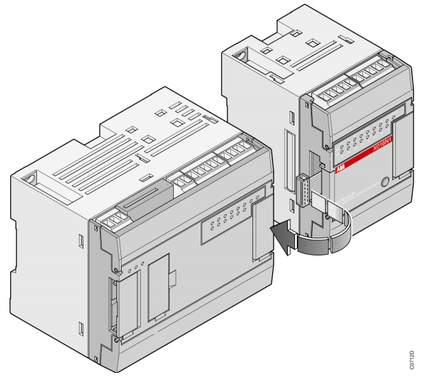
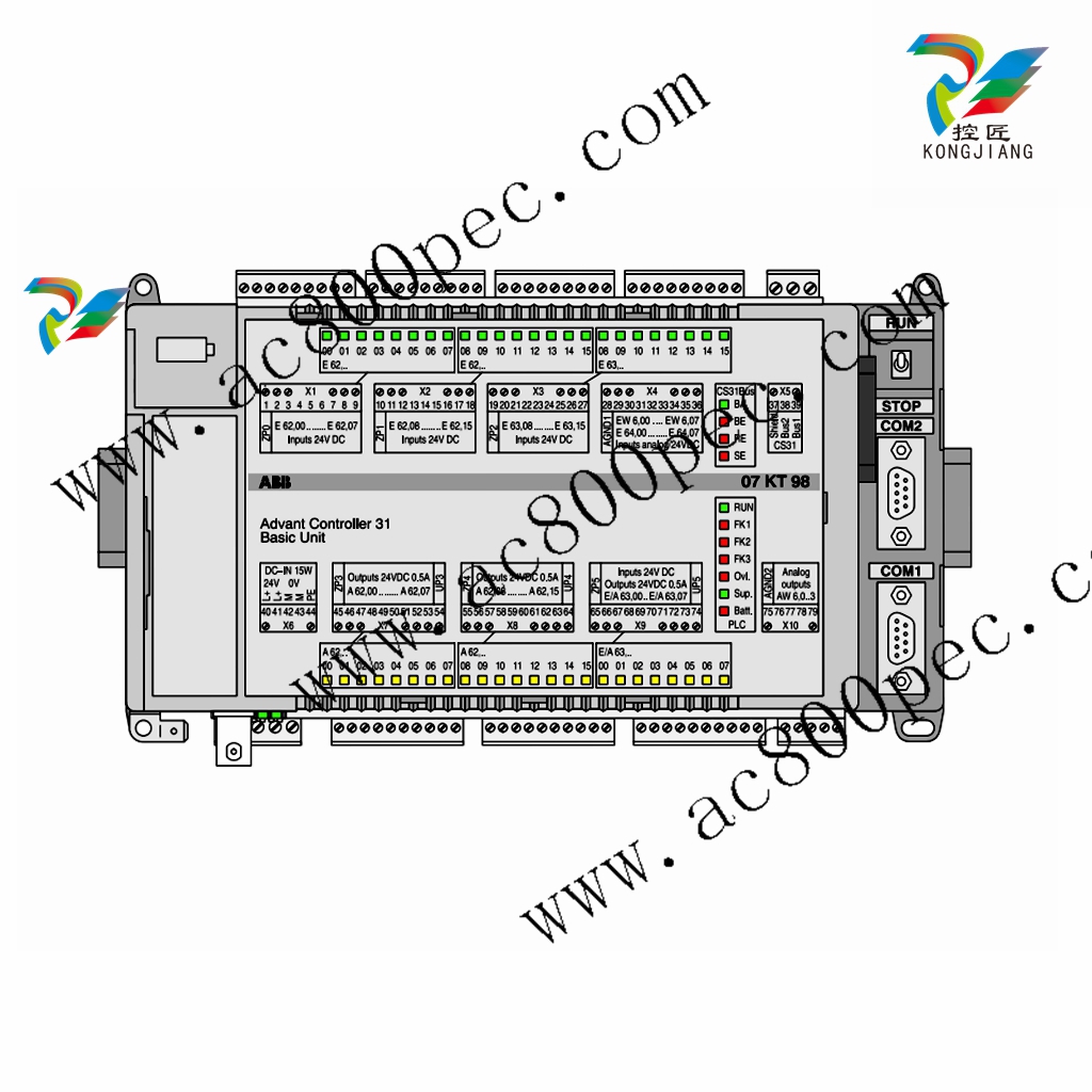
An ABB AC 31 system always includes an AC 31 central unit. There are three types of central
units:
- The 40 series central unit, with a local inputs / outputs extensions interface
- The 50 series central unit, with a local inputs / outputs extensions interface
and a CS 31 bus interface
- The 90 series central unit, with a CS 31 bus interface
Each central unit incorporates a specific number of binary inputs / outputs and occasionally
analog. It is possible, depending on the central unit, to increase the number of inputs / outputs,
to add input / output extensions connected directly to the central units or remote input / output
units via the CS 31 twisted pair.
The 40 and 50 series. It’s possible to increase the number of inputs / outputs of the basic
central unit by adding up to 6 local extension units of either type, binary or analog (Figure 1-1).
2.2. Central units with CS 31 bus
The 50 and 90 series. It’s possible to increase the number of inputs / outputs of the basic
central unit by adding remote units. The central unit controlling the system is called the
MASTER central unit. The maximum bus length is 500 m without an amplifier and 2000 m with
3 amplifiers (1 NCB or NCBR unit enables bus amplification for 500 m).
The master central unit can manage up to 31 connection points called SLAVES, such as:
- A remote unit with extension possibilities: a maximum of 6 extension units comprising of a
maximum of 8 analog input channels and 8 analog output channels
- A simple remote unit (without extension) with analog or binary inputs / outputs
- A remote TCAD display
- An ABB NCSA-01 variable speed drive interface
- A high speed counter unit
- A central unit (50 series with extension possibilities, 90 series and the previous 30 series)
- Or any other device which disposes of a CS 31 communication (see Figure 1-2).
Comment:
A slave fitted solely with binary channels occupies 1 connection point.
A slave fitted with binary and analog channels occupies 2 connection points of the available
31.
The maximum number of remote ANALOG units depends on the MASTER central unit:
- 50 series: - a maximum of 31 remote analog input units
- a maximum of 31 remote analog output units
- a maximum of 15 extensible remote units (ICMK14F1) with analog input / output
extensions + 1 remote analog input / output unit (15 x 2 + 1 = 31)
- or a mixed binary / analog configuration within the previous limits
- 90 series: - a maximum of 12 remote analog input units
- a maximum of 12 remote analog output units
- or a maximum of 12 slaves with analog extensions
Other Option: You have a possibility to use and configure the CS31 bus in Modbus® slave or
master see chapter 7 communication Modbus®
2.3. Cabling techniques
Connecting a central unit without a remote unit is simple and corresponds to normal electrical
standards. The electrical connections of a AC 31 system which consists of remote units,
notably where there are numerous electrical cubicles, should adhere to the obligatory rules.
These rules are presented in chapter 4.
The 40 and 50 series central units memory is composed of two distinct areas:
- A SRAM memory where the user program and data is loaded.
- A Flash EPROM memory which contains:
- a backup of the user program with the program constants,
- the configuration data,
- and the system program protected against access from the user program.
An incorporated battery, which is available only in the 50 series, also enables the backup of
internal variables.
The user program is a set of universal functions conceived by the constructor to cover all
applications and ensure all the basic PLC functions. It is developed with the AC31GRAF
software. After being translated into instructions understable by the central unit it is loaded in
RUN or STOP mode into the SRAM and then saved from the SRAM to the Flash EPROM.
Thereby, at each program launch the user program, saved in the Flash EPROM, is copied to
the SRAM for processing by the microprocessor (Figure 1-3).
The structure of the system program memory, the user program, the inputs / outputs and
internal variables are described in the annex (mapping).
07CR41,24 V直流1SBP260020R1001
07CR41 120/230VAC1SBP260021R1001
07CT41 24VDC1SBP260022R1001
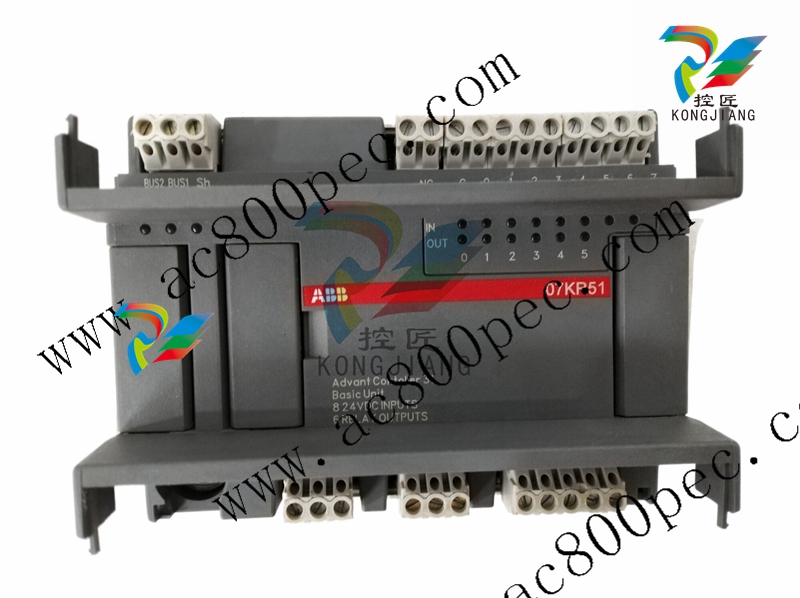
07KR51 24VDC 1SBP260010R1001
07KR51 120/230VAC1SBP260011R1001
07KT51 24VDC1SBP260012R1001
The central unit microprocessor ensures the cyclic execution of the system as shown in
Figure 1-4.
The internal processing:
- PLC monitoring and control
- and processing requests from the terminal operator,
is executed in parallel with the previously described cycle.
The main program is processed sequentially. It may call up to a maximum of 12 sub-programs.
Each sub-program may be called numerous times in the main program.
Three types of interruptions may be executed parallel to the main program:
- A cyclic interruption
- A warning interruption triggered by an event on the I 62.03 input
- A warning interruption triggered by an event on the I 62.02 input
The interruptions have priority over the main program execution. If all three interruptions are
triggered simultaneously then the interruption triggered by I 62.03 has priority over the I 62.02
input interruption which in turn has priority over the cyclic interruption. Once an interruption has
been launched it cannot be interrupted by another (Figure 1-5).
The execution duration of a cycle (bus cycle + program cycle) is controlled by the central unit.
Any excess of the cycle time defined by the user in AC31GRAF is signaled by the ERR Led, at
the front of the central unit, as of the first program cycle.
3.3. Bus transmission
The master central unit manages the transmission of messages to the various slaves over a
RS485 serial liaison.
The messages are transmitted under the following format:
- Request from the master central unit:
address data CRC8
- Request from the remote units:
start data CRC8
The messages always end with an end of frame control: checksum CRC8.
The length of the exchanged frames depends on the type of unit. Frames exchanged with an
analog unit are the longest.
- YOKOGAWA
- Reliance
- ADVANCED
- SEW
- ProSoft
- WATLOW
- Kongsberg
- FANUC
- VSD
- DCS
- PLC
- man-machine
- Covid-19
- Energy and Gender
- Energy Access
- Renewable Integration
- Energy Subsidies
- Energy and Water
- Net zero emission
- Energy Security
- Critical Minerals
- A-B
- petroleum
- Mine scale
- Sewage treatment
- cement
- architecture
- Industrial information
- New energy
- Automobile market
- electricity
- Construction site
- HIMA
- ABB
- Rockwell
- Schneider Modicon
- Siemens
- xYCOM
- Yaskawa
- Woodward
- BOSCH Rexroth
- MOOG
- General Electric
- American NI
- Rolls-Royce
- CTI
- Honeywell
- EMERSON
- MAN
- GE
- TRICONEX
- Control Wave
- ALSTOM
- AMAT
- STUDER
- KONGSBERG
- MOTOROLA
- DANAHER MOTION
- Bentley
- Galil
- EATON
- MOLEX
- Triconex
- DEIF
- B&W
- ZYGO
- Aerotech
- DANFOSS
- KOLLMORGEN
- Beijer
- Endress+Hauser
- schneider
- Foxboro
- KB
- REXROTH
- YAMAHA
- Johnson
- Westinghouse
- WAGO
- TOSHIBA
- TEKTRONIX
- BENDER
- BMCM
- SMC
- HITACHI
- HIRSCHMANN
- XP POWER
- Baldor
- Meggitt
- SHINKAWA
- Other Brands
- UniOP
- KUKA
- IBA
- Beckhoff
- ADLINK
51
-
Beckhoff EP9224-0037 - 4-Channel Power Distribution Box EtherCAT
-
Beckhoff CX2900-0026 - Solid State Flash Memory Card 20GB CFast
-
Beckhoff BK7500 - SERCOS Interface Fieldbus Bus Coupler Terminal
-
Beckhoff Ep2328-0002 - 4-Channel Input 4-Channel Output EtherCAT Box IP67
-
Beckhoff CX1020-0111 - Controller Kit Combo Interface Modules
-
B&R X20AI2237 - X20 System Analog Input Interface Module
-
Beckhoff CP2221-0010 - Multi-Touch Built-In Panel PC Touchscreen
-
Beckhoff CX1500-M310 - Fieldbus Master Interface Module 24V
-
Beckhoff CX2100-0904 - Power Charging Module Smart UPS Extension
-
Beckhoff CP3918-0000 - Multi-Touch Control Panel 18.5-Inch Monitor
-
Beckhoff CP2915-0000 - 15-Inch Multi-Touch Built-In Control Panel
-
Beckhoff CP7037-1027 - HMI Industrial Control Panel Built-In PC
-
Beckhoff EL3152 - 2-Channel Analog Input Terminal 4-20mA EtherCAT
-
Beckhoff CP6607-0000-0020 - 5.7-Inch Built-In Panel PC HMI Touch
-
Beckhoff EJ1809-0000 - 16-Channel Digital Input Pluggable Signal Level Terminal
-
Beckhoff AM8563-0N10-0000 - Synchronous Servo Motor
-
Beckhoff AX2006-S60600-520 - Compact Servo Drive Inverter
-
Beckhoff AM8053-0K20-0000 - Servo Motor with Planetary Gearbox AG3210
-
Beckhoff AM8042-0FH1-0000 - Synchronous Servo Motor
-
Rexroth R911338600 - IndraControl V HMI Terminal Beckhoff PCI Card FC9002
-
Beckhoff AX5125-0000 - 3 Phase Industrial Servo Drive 1000Hz
-
Beckhoff EP2328-0002 - 4-Channel Digital Input 4-Channel Output EtherCAT Box
-
B&R 7CP476-02 - System 2005 RTD CPU Module 3IF681.86 Interface
-
Beckhoff AX8620-0000-0000 - Power Supply Module Axis Drive System
-
Beckhoff CX1010-0111 - PLC Module CPU Controller 24V
-
Beckhoff AM8043-0H10-0000 - Synchronous Servo Motor
-
Beckhoff C6240-1009 - Control Cabinet Industrial PC Mainframe
-
Beckhoff BX8000-0000 - Bus Terminal Controller HW 4.4 Standalone
-
Beckhoff CP7721-1089-0020 - 12.1-Inch Touch Screen HMI Panel PC
-
Beckhoff CP7132-0001 - Industrial Built-In Panel PC Screen
-
Beckhoff CP2912-0010 - Multi-Touch Built-In Control Panel Display
-
Beckhoff CP2915-0000 - 15-Inch Multi-Touch Built-In Control Panel
-
Beckhoff AM8532-1EN0-0000 - Synchronous Servo Motor
-
Beckhoff AX5203-0000 - 2-Channel Digital Compact Servo Drive
-
Beckhoff CX2020-0141 - Embedded PC Core CPU Module
-
Beckhoff CP6832-0002-0010 - Built-In Industrial Control Panel Display
-
Beckhoff CX5020-0112 - Embedded PC CPU Control Module
-
Beckhoff CX5140-0175 - 4GB Embedded PC CPU Unit 24V
-
Beckhoff EL3681-0030 - Digital Multimeter Calibration Terminal EtherCAT
-
Beckhoff CP7201-1000-0000 - Industrial PC Touch Screen HMI Monitor
-
Beckhoff CP7232-1001-0000 - Industrial Panel PC Touch Screen
-
Beckhoff C6930-1032-0040 - Control Cabinet Industrial PC System
-
Beckhoff AX5125-0000 - 3 Phase Industrial Servo Drive 1000Hz
-
Beckhoff CP3916-1424-0000 - Multi-Touch Built-In Control Panel
-
B&R 1900071142 - Lemoine Fieldbus Communication Interface Module
-
Beckhoff EL2872 - 16-Channel Ribbon Cable Digital Output Terminal
-
Beckhoff CX2030-0120 - Embedded PC CPU Base Module Controller
-
Beckhoff CP3919-0000 - 19-Inch Multi-Touch Control Panel Touchscreen
-
Beckhoff AX5101-0000-0202 - Servo Driver Compact Intelligent Drive 180V
-
Beckhoff CX5130-0135 - Embedded PC Controller Module
-
Beckhoff CP3719-1061-0010 - Multi-Touch Panel PC Outer Housing Enclosure
-
Beckhoff CP3919-1033-0000 - 19-Inch Touch Industrial Panel Keyboard
-
Beckhoff CX5020-0111 - Embedded PC PLC CPU Module
-
Beckhoff FC5102-0000 - 2-Channel CANopen PCI Control Board Card
-
Beckhoff CX9001-1101 - Embedded PC CPU Network I/O System Module
-
Beckhoff CX1100-0920 - Smart Position Sensor Interface Module
-
B&R 4P3040.01-490 - Operator Panel PLC Interface Communication Module
-
Beckhoff CP2612-0000 - Dual-Touch Built-In Panel PC HMI
-
Beckhoff CP7002-1043-0010 - Touchscreen Display HMI Panel Terminal
-
Beckhoff CX9020-0115 - Embedded PC Controller Module
-
Beckhoff CX5140-0155 - 4GB Embedded PC CPU Module Die Industry
-
B&R 7DI435.7 - System 2005 Universal Digital Input Output Module
-
Bihl+Wiedemann BWU1568 - AS-i Master to Profibus Gateway Module
-
Beckhoff C6920-0070 - Control Cabinet Industrial PC 8GB Win 10
-
B&R X20AI2322 - 2-Channel Temperature Analog Input Module
-
Beckhoff CP2912-0000 - 12-Inch Touchscreen Display Monitor Screen
-
Beckhoff CP6022-1001-0010 - 15-Inch Built-In Control Panel
-
Beckhoff AM8031-0D10-0000 - Synchronous Servo Motor
-
Beckhoff CX5010-0111 - Embedded PC Controller CPU Module
-
Beckhoff CP7232-1000-0000 - Industrial Panel PC Touch Display Screen
-
Beckhoff CP7802-0011-0000 - 15-Inch Industrial Touchscreen Control Panel
-
Beckhoff C6320 - Control Cabinet Industrial PC
-
Beckhoff CX1030-0012 - Basic CPU Module Windows CE 6.0
-
Beckhoff CP2919-0000 - Installation Multi-Touch Control Panel
-
Beckhoff CX1020-0000 - Controller Set Stack System Pack
-
B&R 3DO480.6 - System 2005 Digital Output Module
-
Beckhoff EL3101 - 1-Channel Analog Input Terminal Differential +/-10V
-
Beckhoff AX8108-0200-0000 - Axis Feed Module Servo Drive
-
Beckhoff CP7802-1241-0010 - 15-Inch Industrial Touchscreen Control Panel
-
Beckhoff FC2002-0000 - 2-Channel Lightbus Data Acquisition PCI Card
-
Beckhoff CX5120-0155 - 2GB Embedded PC Intel Atom Controller
-
Beckhoff Cx9020-0111 - 1GB Basic CPU Module Embedded PC
-
Beckhoff CP6901-0001-0000 - 12-Inch Economy Built-In Control Panel
-
Beckhoff CX9020-0111 - Embedded PC CPU Basic Module
-
Beckhoff CX5130-0100 - 4GB Embedded PC CPU Module
-
Beckhoff CP2715-0010 - Multi-Touch Built-In Panel PC
-
Beckhoff CX2033-0175 - Embedded PC CPU Module Core i7
-
Beckhoff CP7201-1000-0000 - 12-Inch Touchscreen Panel PC AMAT Green Box
-
Beckhoff EL4038 - 8-Channel Analog Output Terminal 0-10V EtherCAT
-
Beckhoff CP6802-0000-0000 - Built-In Control Panel HMI Screen
-
Beckhoff AM8042-0F21-0000 - Synchronous Servo Motor
-
Beckhoff CX5120-0141 - Embedded PC Basic Controller Module
-
Beckhoff C6930-0050 - Control Cabinet Industrial PC System
-
Beckhoff CP6831-0002-0000 - Built-In Industrial Control Panel
-
Beckhoff CP6919-0001-0000 - Built-In Control Panel Display Unit
-
Beckhoff CP7201-1019-0030 - Built-In Panel PC HMI Monitor Screen
-
Beckhoff CP6809-0001-0000 - 6.5-Inch Touch Panel ELO Accutouch HMI
-
Beckhoff CX1020-0000 - Control Kit Combo Stack Units
-
Beckhoff cp3918-1012-0000 - 18.5-Inch Multi-Touch Control Panel
-
Beckhoff CX5140-0123 - 4GB Embedded PC CPU Module
-
Beckhoff C3230TP - Industrial PC Rackmount Workstation
-
Beckhoff CP6801-1006-0010 - Touch Panel HMI Display Unit
-
Beckhoff CX8010 - Embedded PC Controller Module
-
Beckhoff CP7011-0001 - Control Panel CRT Operator Pendant Monitor HMI
-
Beckhoff CX1010-0111 - Embedded PC CPU PLC Module 24V
-
Beckhoff CP2915-0000 - 15-Inch Multi-Touch Built-In Control Panel
-
Beckhoff CP7802 - Industrial Touch Screen Control Panel Monitor
-
Siemens 6AV7452-1AB00-0FB0 - Industrial PC Panel 877 Beckhoff PCI Cards
-
Beckhoff CP2612-0000 - Dual-Touch Integrated Panel Monitor Screen
-
Beckhoff CX5140-0175 - Embedded PC Core Controller
-
Beckhoff Cp6202-0001-0010 - Economy Built-In Panel PC System
-
Beckhoff C6320-0010 - Control Cabinet Industrial PC Unit
-
Beckhoff CP2919-0000 - Multi-Touch Built-In Control Panel Screen
-
Beckhoff CX9020-0111 - Embedded PC CPU Controller Module
-
B&R 3BP151.41 - System 2005 Backplane Base Module
-
Siemens 6AV7452-1AB00-0FB0 - Panel PC 877 with Beckhoff Communication Cards FC3101 FC7501
-
Beckhoff CX9001-1101 - Embedded PC System Fieldbus Module Bundle
-
Beckhoff CX1001-0122 - CPU Module PLC Controller 128MB RAM
-
Beckhoff CX5130-0175 - Embedded PC CPU Module Intel Atom Storage Card
-
Beckhoff C6140 - Industrial PC Tower Casing Pent 4 System
-
Beckhoff CX5020-0120 - Embedded PC Controller Core Module
-
Beckhoff C6017-0010 - Ultra-Compact Industrial PC
-
Beckhoff CP6809-0000-0000 - 6.5-Inch Industrial Panel Control Display
-
Beckhoff AX5021-0000-0000 - Brake Chopper Module Axis System
-
Beckhoff AM8031-0D10-0000 - Synchronous Servo Motor
-
Beckhoff CX8010 - Embedded PC Microcontroller Module
-
Beckhoff CP6202-1070-0070 - Built-In Panel PC HMI Touchscreen
-
Beckhoff C6920-0000 - Control Cabinet Industrial PC Module

K-JIANG

Add: Jimei North Road, Jimei District, Xiamen, Fujian, China
Tell:+86-15305925923